More Related Content
Similar to Mechanical Engineering Metal Casting Presantion
Similar to Mechanical Engineering Metal Casting Presantion (20)
Mechanical Engineering Metal Casting Presantion
- 1. ©2010 John Wiley & Sons, Inc. M P Groover, Principals of Modern Manufacturing 4/e SI Version
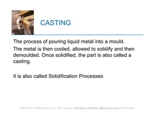
CASTING
The process of pouring liquid metal into a mould.
The metal is then cooled, allowed to solidify and then
demoulded. Once solidified, the part is also called a
casting.
It is also called Solidification Processes
- 2. ©2010 John Wiley & Sons, Inc. M P Groover, Principals of Modern Manufacturing 4/e SI Version
Solidification Processes
Starting work material is either a liquid or is in a highly
plastic condition, and a part is created through
solidification of the material
Solidification processes can be classified according to
engineering material processed:
Metals
Ceramics, specifically glasses
Polymers and polymer matrix composites (PMCs)
https://www.youtube.com/watch?v=yq4yMae3aX4
- 3. ©2010 John Wiley & Sons, Inc. M P Groover, Principals of Modern Manufacturing 4/e SI Version
Classification of solidification processes
- 4. ©2010 John Wiley & Sons, Inc. M P Groover, Principals of Modern Manufacturing 4/e SI Version
Casting of Metals
Process in which molten metal flows by gravity or other
force into a mold where it solidifies in the shape of
the mold cavity
The term casting also applies to the part made in the
process
Steps in casting seem simple:
1. Melt the metal
2. Pour it into a mold
3. Let it freeze
- 5. ©2010 John Wiley & Sons, Inc. M P Groover, Principals of Modern Manufacturing 4/e SI Version
Capabilities and Advantages of
Casting
Can create complex part geometries
Can create both external and internal shapes
Some casting processes are net shape; others are
near net shape
Can produce very large parts
Some casting methods are suited to mass production
- 6. ©2010 John Wiley & Sons, Inc. M P Groover, Principals of Modern Manufacturing 4/e SI Version
Disadvantages of Casting
Different disadvantages for different casting
processes:
Limitations on mechanical properties
Poor dimensional accuracy and surface finish for
some processes; e.g., sand casting
Safety hazards to workers due to hot molten
metals
Environmental problems
- 7. ©2010 John Wiley & Sons, Inc. M P Groover, Principals of Modern Manufacturing 4/e SI Version
Parts Made by Casting
Big parts
Engine blocks and heads for automotive
vehicles, wood burning stoves, machine frames,
railway wheels, pipes, church bells, big statues,
pump housings
Small parts
Dental crowns, jewelry, small statues, frying
pans
- 8. ©2010 John Wiley & Sons, Inc. M P Groover, Principals of Modern Manufacturing 4/e SI Version
Overview of Casting Technology
Casting is usually performed in a foundry
Foundry = factory equipped for making molds, melting
and handling molten metal, performing the casting
process, and cleaning the finished casting
Workers who perform casting are called foundrymen
- 9. ©2010 John Wiley & Sons, Inc. M P Groover, Principals of Modern Manufacturing 4/e SI Version
The Mold in Casting
Contains cavity whose geometry determines part
shape
Actual size and shape of cavity must be slightly
enlarged to allow for shrinkage of metal during
solidification and cooling
Molds are made of a variety of materials,
including sand, plaster, ceramic, and metal
- 10. ©2010 John Wiley & Sons, Inc. M P Groover, Principals of Modern Manufacturing 4/e SI Version
Open Molds and Closed Molds
Two forms of mold: (a) open mold and (b) closed mold
for more complex mold geometry with gating system
leading into the cavity
- 11. ©2010 John Wiley & Sons, Inc. M P Groover, Principals of Modern Manufacturing 4/e SI Version
Two Categories of
Casting Processes
1. Expendable mold processes – use an expendable
mold which must be destroyed to remove casting
Mold materials: sand, plaster, and similar
materials, plus binders
Advantage: more complex shapes possible
Disadvantage: production rates often limited by
the time to make mold rather than casting itself
- 12. 2. Permanent mold processes – use a permanent mold
which can be used to produce many castings
Made of metal (or, less commonly, a ceramic
refractory material
Advantage: higher production rates
Disadvantage: geometries limited by need to open
mold
©2010 John Wiley & Sons, Inc. M P Groover, Principals of Modern Manufacturing 4/e SI Version
- 13. ©2010 John Wiley & Sons, Inc. M P Groover, Principals of Modern Manufacturing 4/e SI Version
Advantages and Disadvantages
More intricate geometries are possible with
expendable mold processes
Part shapes in permanent mold processes are limited
by the need to open the mold
Permanent mold processes are more economic in
high production operations
- 14. ©2010 John Wiley & Sons, Inc. M P Groover, Principals of Modern Manufacturing 4/e SI Version
Sand Casting Mold
- 15. ©2010 John Wiley & Sons, Inc. M P Groover, Principals of Modern Manufacturing 4/e SI Version
Terminology for
Sand Casting Mold
Mold consists of two halves:
Cope = upper half of mold
Drag = bottom half
Mold halves are contained in a box, called a flask
The two halves separate at the parting line
- 16. ©2010 John Wiley & Sons, Inc. M P Groover, Principals of Modern Manufacturing 4/e SI Version
Forming the Mold Cavity
in Sand Casting
Mold cavity is formed by packing sand around a
pattern, which has the shape of the part
When the pattern is removed, the remaining cavity of
the packed sand has desired shape of cast part
The pattern is usually oversized to allow for
shrinkage of metal during solidification and cooling
Sand for the mold is moist and contains a binder to
maintain its shape
- 17. ©2010 John Wiley & Sons, Inc. M P Groover, Principals of Modern Manufacturing 4/e SI Version
Use of a Core in the Mold Cavity
The mold cavity provides the external surfaces of the
cast part
In addition, a casting may have internal surfaces,
determined by a core, placed inside the mold cavity
to define the interior geometry of part
In sand casting, cores are generally made of sand
- 18. ©2010 John Wiley & Sons, Inc. M P Groover, Principals of Modern Manufacturing 4/e SI Version
Gating System
Channel through which molten metal flows into cavity
from outside of mold
Consists of a downsprue, through which metal enters
a runner leading to the main cavity
At the top of downsprue, a pouring cup is often used
to minimize splash and turbulence as the metal flows
into downsprue
- 19. ©2010 John Wiley & Sons, Inc. M P Groover, Principals of Modern Manufacturing 4/e SI Version
Riser
Reservoir in the mold which is a source of liquid metal
to compensate for shrinkage of the part during
solidification
The riser must be designed to freeze after the main
casting in order to satisfy its function
- 20. ©2010 John Wiley & Sons, Inc. M P Groover, Principals of Modern Manufacturing 4/e SI Version
Heating the Metal
Heating furnaces are used to heat the metal to
molten temperature sufficient for casting
The heat required is the sum of:
1. Heat to raise temperature to melting point
2. Heat of fusion to convert from solid to liquid
3. Heat to raise molten metal to desired
temperature for pouring
- 21. ©2010 John Wiley & Sons, Inc. M P Groover, Principals of Modern Manufacturing 4/e SI Version
- 22. ©2010 John Wiley & Sons, Inc. M P Groover, Principals of Modern Manufacturing 4/e SI Version
Pouring the Molten Metal
For this step to be successful, metal must flow into all
regions of the mold, most importantly the main cavity,
before solidifying
Factors that determine success
Pouring temperature
Pouring rate
Turbulence
- 23. ©2010 John Wiley & Sons, Inc. M P Groover, Principals of Modern Manufacturing 4/e SI Version
Solidification of Metals
Transformation of molten metal back into solid state
Solidification differs depending on whether the metal
is
A pure element or
An alloy
- 24. ©2010 John Wiley & Sons, Inc. M P Groover, Principals of Modern Manufacturing 4/e SI Version
Cooling Curve for a Pure Metal
A pure metal
solidifies at a
constant
temperature equal
to its freezing
point (same as
melting point)
- 25. ©2010 John Wiley & Sons, Inc. M P Groover, Principals of Modern Manufacturing 4/e SI Version
Solidification of Pure Metals
Due to chilling action of mold wall, a thin skin of solid
metal is formed at the interface immediately after
pouring
Skin thickness increases to form a shell around the
molten metal as solidification progresses
Rate of freezing depends on heat transfer into mold,
as well as thermal properties of the metal
- 26. ©2010 John Wiley & Sons, Inc. M P Groover, Principals of Modern Manufacturing 4/e SI Version
Characteristic grain
structure in a casting of
a pure metal, showing
randomly oriented
grains of small size
near the mold wall, and
large columnar grains
oriented toward the
center of the casting
Solidification of Pure Metals
- 27. ©2010 John Wiley & Sons, Inc. M P Groover, Principals of Modern Manufacturing 4/e SI Version
Solidification Time
Total solidification time TTS = time required for casting
to solidify after pouring
TTS depends on size and shape of casting by
relationship known as Chvorinov's Rule
where TTS = total solidification time; V = volume of the
casting; A = surface area of casting; n = exponent
with typical value = 2; and Cm is mold constant.
n
TS m
V
T C
A
- 28. ©2010 John Wiley & Sons, Inc. M P Groover, Principals of Modern Manufacturing 4/e SI Version
Mold Constant in Chvorinov's
Rule
Mold constant Cm depends on:
Mold material
Thermal properties of casting metal
Pouring temperature relative to melting point
Value of Cm for a given casting operation can be
based on experimental data from previous operations
carried out using same mold material, metal, and
pouring temperature, even though the shape of the
part may be quite different
- 29. ©2010 John Wiley & Sons, Inc. M P Groover, Principals of Modern Manufacturing 4/e SI Version
What Chvorinov's Rule Tells Us
Casting with a higher volume-to-surface area ratio cools
and solidifies more slowly than one with a lower ratio
To feed molten metal to the main cavity, TTS for
riser must be greater than TTS for main casting
Since mold constants of riser and casting will be equal,
design the riser to have a larger volume-to-area ratio so
that the main casting solidifies first
This minimizes the effects of shrinkage
- 30. ©2010 John Wiley & Sons, Inc. M P Groover, Principals of Modern Manufacturing 4/e SI Version
- 31. ©2010 John Wiley & Sons, Inc. M P Groover, Principals of Modern Manufacturing 4/e SI Version
Shrinkage during Solidification
and Cooling
(0) starting level of molten metal immediately after
pouring; (1) reduction in level caused by liquid
contraction during cooling
- 32. ©2010 John Wiley & Sons, Inc. M P Groover, Principals of Modern Manufacturing 4/e SI Version
Shrinkage during Solidification
and Cooling
(2) reduction in height and formation of shrinkage cavity
caused by solidification; (3) further reduction in volume
due to thermal contraction during cooling of solid metal
- 33. ©2010 John Wiley & Sons, Inc. M P Groover, Principals of Modern Manufacturing 4/e SI Version
Solidification Shrinkage
Occurs in nearly all metals because the solid phase
has a higher density than the liquid phase
Thus, solidification causes a reduction in volume per
unit weight of metal
Exception: cast iron with high C content
Graphitization during final stages of freezing
causes expansion that counteracts volumetric
decrease associated with phase change
- 34. ©2010 John Wiley & Sons, Inc. M P Groover, Principals of Modern Manufacturing 4/e SI Version
Shrinkage Allowance
Patternmakers correct for solidification shrinkage and
thermal contraction by making the mold cavity
oversized
Amount by which mold is made larger relative to final
casting size is called pattern shrinkage allowance
Casting dimensions are expressed linearly, so
allowances are applied accordingly
- 35. ©2010 John Wiley & Sons, Inc. M P Groover, Principals of Modern Manufacturing 4/e SI Version
External Chills
(a) External chill to encourage rapid freezing of the
molten metal in a thin section of the casting; and (b) the
likely result if the external chill were not used
- 36. ©2010 John Wiley & Sons, Inc. M P Groover, Principals of Modern Manufacturing 4/e SI Version
Steps in Sand Casting
1. Pour the molten metal into sand mold
2. Allow time for metal to solidify
3. Break up the mold to remove casting
4. Clean and inspect casting
Separate gating and riser system
5. Heat treatment of casting is sometimes required to
improve metallurgical properties
- 37. The cavity in the sand mold is formed by packing
sand around a pattern, then separating the mold into
two halves and removing the pattern
The mold must also contain gating and riser system
If casting is to have internal surfaces, a core must be
included in mold
A new sand mold must be made for each part
produced
©2010 John Wiley & Sons, Inc. M P Groover, Principals of Modern Manufacturing 4/e SI Version
Making the Sand Mold
- 39. ©2010 John Wiley & Sons, Inc. M P Groover, Principals of Modern Manufacturing 4/e SI Version
The Pattern
Full-sized model of part, slightly enlarged to account for
shrinkage and machining allowances in the casting
Pattern materials:
Wood - common material because it is easy to
work, but it warps
Metal - more expensive to fabricate, but lasts
longer
Plastic - compromise between wood and metal
- 40. ©2010 John Wiley & Sons, Inc. M P Groover, Principals of Modern Manufacturing 4/e SI Version
Types of Patterns
Types of patterns used in sand casting: (a) solid
pattern, (b) split pattern, (c) match-plate pattern, (d)
cope and drag pattern
- 41. ©2010 John Wiley & Sons, Inc. M P Groover, Principals of Modern Manufacturing 4/e SI Version
Core
Full-scale model of interior surfaces of part
Inserted into mold cavity prior to pouring
The molten metal flows and solidifies between the
mold cavity and the core to form the casting's
external and internal surfaces
May require supports to hold it in position in the mold
cavity during pouring, called chaplets
- 42. ©2010 John Wiley & Sons, Inc. M P Groover, Principals of Modern Manufacturing 4/e SI Version
Core in Mold
(a) Core held in place in the mold cavity by chaplets,
(b) possible chaplet design, (c) casting
- 43. ©2010 John Wiley & Sons, Inc. M P Groover, Principals of Modern Manufacturing 4/e SI Version
Desirable Mold Properties
Strength - to maintain shape and resist erosion
Permeability - to allow hot air and gases to pass
through voids in sand
Thermal stability - to resist cracking on contact with
molten metal
Collapsibility - ability to give way and allow casting to
shrink without cracking the casting
Reusability - can sand from broken mold be reused to
make other molds?
- 44. ©2010 John Wiley & Sons, Inc. M P Groover, Principals of Modern Manufacturing 4/e SI Version
Foundry Sand
Silica (SiO2) or silica mixed with other minerals
Good refractory properties - for high temperatures
Small grain size for better surface finish on cast part
Large grain size is more permeable, allowing gases
to escape during pouring
Irregular grain shapes strengthen molds due to
interlocking, compared to round grains
Disadvantage: interlocking reduces permeability
- 45. ©2010 John Wiley & Sons, Inc. M P Groover, Principals of Modern Manufacturing 4/e SI Version
Binders Used with
Foundry Sand
Sand is held together by a mixture of water and
bonding clay
Typical mix: 90% sand, 3% water, and 7% clay
Other bonding agents also used in sand molds:
Organic resins (e g , phenolic resins)
Inorganic binders (e g , sodium silicate and
phosphate)
Additives are sometimes combined with the mixture
to increase strength and/or permeability
- 46. ©2010 John Wiley & Sons, Inc. M P Groover, Principals of Modern Manufacturing 4/e SI Version
Types of Sand Mold
Green-sand molds - mixture of sand, clay, and water
“Green" means mold contains moisture at time of
pouring
Dry-sand mold - organic binders rather than clay
Mold is baked to improve strength
Skin-dried mold - drying mold cavity surface of a
green-sand mold to a depth of 10 to 25 mm, using
torches or heating lamps
- 47. ©2010 John Wiley & Sons, Inc. M P Groover, Principals of Modern Manufacturing 4/e SI Version
Buoyancy in a
Sand Casting Operation
During pouring, buoyancy of the molten metal tends
to displace the core, which can cause casting to be
defective
Force tending to lift core = weight of displaced liquid
less the weight of core itself
Fb = Wm - Wc
where Fb = buoyancy force; Wm = weight of molten
metal displaced; and Wc = weight of core
- 48. ©2010 John Wiley & Sons, Inc. M P Groover, Principals of Modern Manufacturing 4/e SI Version
Other Expendable Mold
Processes
Shell Molding
Vacuum Molding
Expanded Polystyrene Process
Investment Casting
Plaster Mold and Ceramic Mold Casting
- 49. ©2010 John Wiley & Sons, Inc. M P Groover, Principals of Modern Manufacturing 4/e SI Version
Permanent Mold
Casting Processes
Economic disadvantage of expendable mold casting:
A new mold is required for every casting
In permanent mold casting, the mold is reused many
times
The processes include:
Basic permanent mold casting
Die casting
Centrifugal casting
- 50. ©2010 John Wiley & Sons, Inc. M P Groover, Principals of Modern Manufacturing 4/e SI Version
The Basic Permanent Mold
Process
Uses a metal mold constructed of two sections
designed for easy, precise opening and closing
Molds used for casting lower melting point alloys are
commonly made of steel or cast iron
Molds used for casting steel must be made of
refractory material, due to the very high pouring
temperatures
- 51. ©2010 John Wiley & Sons, Inc. M P Groover, Principals of Modern Manufacturing 4/e SI Version
Steps in
Permanent Mold Casting
(1) Mold is preheated and coated for lubrication and
heat dissipation
- 52. ©2010 John Wiley & Sons, Inc. M P Groover, Principals of Modern Manufacturing 4/e SI Version
Steps in
Permanent Mold Casting
(2) Cores (if any
are used) are
inserted and
mold is closed
- 53. ©2010 John Wiley & Sons, Inc. M P Groover, Principals of Modern Manufacturing 4/e SI Version
Steps in
Permanent Mold Casting
(3) Molten metal is
poured into the mold,
where it solidifies
- 54. ©2010 John Wiley & Sons, Inc. M P Groover, Principals of Modern Manufacturing 4/e SI Version
Permanent Mold Casting:
Advantages and Limitations
Advantages of permanent mold casting:
Good dimensional control and surface finish
Rapid solidification caused by metal mold results in
a finer grain structure, so castings are stronger
Limitations:
Generally limited to metals of lower melting point
Simpler part geometries compared to sand casting
because of need to open the mold
High cost of mold
- 55. ©2010 John Wiley & Sons, Inc. M P Groover, Principals of Modern Manufacturing 4/e SI Version
Applications and Metals for
Permanent Mold Casting
Due to high mold cost, process is best suited to high
volume production and can be automated accordingly
Typical parts: automotive pistons, pump bodies, and
certain castings for aircraft and missiles
Metals commonly cast: aluminum, magnesium,
copper-base alloys, and cast iron
Unsuited to steels because of very high pouring
temperatures
- 56. ©2010 John Wiley & Sons, Inc. M P Groover, Principals of Modern Manufacturing 4/e SI Version
Die Casting
A permanent mold casting process in which molten
metal is injected into mold cavity under high pressure
Pressure is maintained during solidification, then
mold is opened and part is removed
Molds in this casting operation are called dies; hence
the name die casting
Use of high pressure to force metal into die cavity is
what distinguishes this from other permanent mold
processes
- 57. ©2010 John Wiley & Sons, Inc. M P Groover, Principals of Modern Manufacturing 4/e SI Version
Die Casting Machines
Designed to hold and accurately close two mold
halves and keep them closed while liquid metal is
forced into cavity
Two main types:
1. Hot-chamber machine
2. Cold-chamber machine
- 58. ©2010 John Wiley & Sons, Inc. M P Groover, Principals of Modern Manufacturing 4/e SI Version
Hot-Chamber Die Casting
Metal is melted in a container, and a piston injects liquid
metal under high pressure into the die
High production rates
500 parts per hour not uncommon
Applications limited to low melting-point metals that
do not chemically attack plunger and other
mechanical components
Casting metals: zinc, tin, lead, and magnesium
- 59. ©2010 John Wiley & Sons, Inc. M P Groover, Principals of Modern Manufacturing 4/e SI Version
Hot-Chamber Die Casting
Hot-chamber die
casting cycle: (1)
with die closed
and plunger
withdrawn,
molten metal
flows into the
chamber
- 60. ©2010 John Wiley & Sons, Inc. M P Groover, Principals of Modern Manufacturing 4/e SI Version
Hot-Chamber Die Casting
(2) plunger forces
metal in chamber to
flow into die,
maintaining pressure
during cooling and
solidification.
- 61. ©2010 John Wiley & Sons, Inc. M P Groover, Principals of Modern Manufacturing 4/e SI Version
Hot-Chamber Die Casting
(3) Plunger is
withdrawn, die is
opened, and
casting is ejected
- 62. ©2010 John Wiley & Sons, Inc. M P Groover, Principals of Modern Manufacturing 4/e SI Version
Cold-Chamber Die Casting
Machine
Molten metal is poured into unheated chamber from
external melting container, and a piston injects metal
under high pressure into die cavity
High production but not usually as fast as hot-chamber
machines because of pouring step
Casting metals: aluminum, brass, and magnesium
alloys
Advantages of hot-chamber process favor its use on low
melting-point alloys (zinc, tin, lead)
- 63. ©2010 John Wiley & Sons, Inc. M P Groover, Principals of Modern Manufacturing 4/e SI Version
Cold-Chamber Die Casting Cycle
(1) With die closed and ram withdrawn, molten metal is
poured into the chamber
- 64. ©2010 John Wiley & Sons, Inc. M P Groover, Principals of Modern Manufacturing 4/e SI Version
Cold-Chamber Die Casting Cycle
(2) Ram forces metal to flow into die, maintaining
pressure during cooling and solidification
- 65. ©2010 John Wiley & Sons, Inc. M P Groover, Principals of Modern Manufacturing 4/e SI Version
Cold-Chamber Die Casting Cycle
(3) Ram is withdrawn, die is opened, and part is
ejected
- 66. ©2010 John Wiley & Sons, Inc. M P Groover, Principals of Modern Manufacturing 4/e SI Version
Molds for Die Casting
Usually made of tool steel, mold steel, or maraging
steel
Tungsten and molybdenum (good refractory qualities)
used to die cast steel and cast iron
Ejector pins required to remove part from die when it
opens
Lubricants must be sprayed onto cavity surfaces to
prevent sticking
- 67. ©2010 John Wiley & Sons, Inc. M P Groover, Principals of Modern Manufacturing 4/e SI Version
Die Casting:
Advantages and Limitations
Advantages:
Economical for large production quantities
Good accuracy and surface finish
Thin sections possible
Rapid cooling means small grain size and good
strength in casting
Disadvantages:
Generally limited to metals with low metal points
Part geometry must allow removal from die
- 68. ©2010 John Wiley & Sons, Inc. M P Groover, Principals of Modern Manufacturing 4/e SI Version
Centrifugal Casting
A family of casting processes in which the mold is
rotated at high speed so centrifugal force distributes
molten metal to outer regions of die cavity
The group includes:
True centrifugal casting
Semicentrifugal casting
Centrifuge casting
- 69. ©2010 John Wiley & Sons, Inc. M P Groover, Principals of Modern Manufacturing 4/e SI Version
True Centrifugal Casting
Molten metal is poured into rotating mold to produce a
tubular part
In some operations, mold rotation commences after
pouring rather than before
Parts: pipes, tubes, bushings, and rings
Outside shape of casting can be round, octagonal,
hexagonal, etc , but inside shape is (theoretically)
perfectly round, due to radially symmetric forces
- 70. ©2010 John Wiley & Sons, Inc. M P Groover, Principals of Modern Manufacturing 4/e SI Version
True Centrifugal Casting
Setup for true centrifugal casting
- 71. ©2010 John Wiley & Sons, Inc. M P Groover, Principals of Modern Manufacturing 4/e SI Version
Semicentrifugal Casting
Centrifugal force is used to produce solid castings
rather than tubular parts
Molds use risers at center to supply feed metal
Density of metal in final casting is greater in outer
sections than at center of rotation
Often used on parts in which center of casting is
machined away, thus eliminating the portion where
quality is lowest
Examples: wheels and pulleys
- 72. ©2010 John Wiley & Sons, Inc. M P Groover, Principals of Modern Manufacturing 4/e SI Version
Semicentrifugal Casting
- 73. ©2010 John Wiley & Sons, Inc. M P Groover, Principals of Modern Manufacturing 4/e SI Version
Centrifuge Casting
Mold is designed with part cavities located away from
axis of rotation, so molten metal poured into mold is
distributed to these cavities by centrifugal force
Used for smaller parts
Radial symmetry of part is not required as in other
centrifugal casting methods
- 74. ©2010 John Wiley & Sons, Inc. M P Groover, Principals of Modern Manufacturing 4/e SI Version
Centrifuge Casting