SlideShare a Scribd company logo
1 of 33
Download to read offline
ERP20ALF, ERP25ALF, ERP30ALF (D216) (ERP040-060DH) (D216)
SERVICE MANUAL CONTENTS
SECTION
PART
NUMBER
YRM
NUMBER
REV
DATE
FRAME............................................................................................................................ 524179935 0100 YRM 0582 07/05
DC MOTOR MAINTENANCE.......................................................................................... 524158039 0620 YRM 0294 03/08
AC MOTOR MAINTENANCE.......................................................................................... 524183080 0620 YRM 1053 03/10
DRIVE AXLE, SPEED REDUCER, AND DIFFERENTIAL............................................. 524179938 1400 YRM 0575 03/03
STEERING AXLE............................................................................................................ 524158752 1600 YRM 0316 08/06
STEERING CONTROL UNIT.......................................................................................... 524158753 1600 YRM 0720 11/06
STEERING SYSTEM...................................................................................................... 524183081 1600 YRM 1054 11/06
BRAKE SYSTEM............................................................................................................ 524179943 1800 YRM 0566 03/03
HYDRAULIC SYSTEM.................................................................................................... 524179945 1900 YRM 0559 04/09
MAIN CONTROL VALVE................................................................................................ 524179946 2000 YRM 0562 02/09
TILT CYLINDERS........................................................................................................... 524150790 2100 YRM 0103 03/07
ELECTRICAL SYSTEM.................................................................................................. 524183082 2200 YRM 1055 10/09
AC MOTOR CONTROLLER DESC/CHKS/ADJ/TRBSHT/REP&THEORY OF
OPERATION/DISPLAY PANEL................................................................................. 524183083 2200 YRM 1056 03/09
TROUBLESHOOTING AND ADJUSTMENTS USING THE AC CONTROLS
PROGRAM................................................................................................................. 524183085 2200 YRM 1058 04/11
INDUSTRIAL BATTERY................................................................................................. 524158040 2240 YRM 0001 09/14
MAST - DESCRIPTION................................................................................................... 524158890 4000 YRM 0521 03/06
MAST - REPAIR.............................................................................................................. 524158891 4000 YRM 0522 07/10
METRIC AND INCH (SAE) FASTENERS....................................................................... 524150797 8000 YRM 0231 10/13
DIAGRAMS..................................................................................................................... 524183086 8000 YRM 1059 08/12
PERIODIC MAINTENANCE............................................................................................ 524183087 8000 YRM 1060 02/10
CAPACITIES AND SPECIFICATIONS........................................................................... 524183088 8000 YRM 1061 01/05
PART NO. 524183079 (09/14)
100 YRM 582 Description
General
This section has a description and the service procedures for the parts of the frame. These parts include the frame,
counterweight assembly, overhead guard, hood and seat assembly, access panels, and label positions. The proce-
dure for removing the traction motor is also described in this section.
Description
MAIN FRAME
The main frame is a single weldment. See Figure 1.
The main frame has mounts for the following:
• Counterweight
• Overhead guard,
• Battery restraint and hood
• Tilt cylinders
• Steering axle
• Drive axle assembly
• Cowl assembly
• Floor pedals and floor plates
• Side step and fender weldments
• Hydraulic tank
• Pump and motor assemblies (steer, lift, and traction
motors)
• Control valves, and the levers
The hood is part of the operator and battery restraint
system. The seat is part of the operator restraint sys-
tem. The floor plates can be removed for access to
the traction motor. The panels on the sides of the bat-
tery compartment can also be easily removed. The hy-
draulic tank, lift pump motor assembly, and the steer-
ing pump motor assembly are in a compartment be-
tween the battery and the counterweight. The SCR
(silicon controlled rectifier) or transistor electronic con-
trollers and contactors are in the top of the counter-
weight. The top cover of the counterweight can be re-
moved for access to the controllers and contactors for
early model ERP20-30ALF (B216) lift trucks. See Fig-
ure 2. The rear cover of the counterweight can be re-
moved for access to the controllers and contactors for
later model ERP20-30ALF (B216) trucks and ERP20-
30ALF (ERP040-060DH) (D216) trucks. See Figure 3.
There are two main frames for lift trucks made for use in
North America and two main frames for lift trucks made
for use in Europe. The frames are different because
of the different battery compartment sizes. There are
two battery compartment lengths. The battery com-
partment widths are also different for Europe and North
America. See Battery Specifications, at the back of this
manual.
WARNING
The battery must fit the battery compartment so
that the battery restraint will operate correctly. A
loose battery can cause serious injury and property
damage if the lift truck overturns. Adjust the spacer
plate to prevent the battery from moving more than
13 mm (0.5 in.) forward or backward.
WARNING
Maximum clearance between the battery and bat-
tery compartment width is 13 mm (0.5 in.). Maxi-
mum clearance between the battery and the spacer
plate is also 13 mm (0.5 in.). The Battery Specifica-
tions chart shows the minimum size compartment
allowed.
The weight of the battery is a large part of the coun-
terweight system on an electric lift truck. Make sure
that the battery is within the weight limits indicated on
the nameplate. Each model of lift truck has a cast-iron
counterweight that provides the additional weight nec-
essary for the indicated capacity.
OTHER FRAME WELDMENTS
These frame parts are the right-hand and left-hand side
step and fender weldments, and the cowl weldment.
See Figure 1. Each part is a weldment fastened to
the main frame to make the frame assembly. The cowl
weldment is a mount for the front of the overhead guard
(see Figure 2 and Figure 3), the steering column as-
sembly (see Figure 4, Figure 5, and Figure 6), the re-
lease linkage of the parking brake, and the instrument
panel with light switches. The display panels for these
models of lift trucks are mounted into the instrument
panel. See Figure 4, Figure 5, and Figure 6.
1
Description 100 YRM 582
1. COWL
2. BATTERY SPACER PLATE
3. BATTERY RETAINER ROD
4. FRAME
5. SIDE STEP AND FENDER WELDMENT
6. ACCESS PANEL
7. FLOOR PLATES
Figure 1. Lift Truck Main Frame
Legend for Figure 2
1. OVERHEAD GUARD
2. COVER OF ELECTRONICS
COMPARTMENT
3. COUNTERWEIGHT
4. TOW PIN AND HANDLE
5. CAPSCREW
6. LOCKWASHER
7. WASHER
8. HANDLE
9. SCREW
10. NUT
11. FOAM TAPE
2
100 YRM 582 Description
Figure 2. Overhead Guard and Counterweight Early Model ERP20-30ALF (B216) Trucks
3
Description 100 YRM 582
OVERHEAD GUARD
WARNING
Do not operate the lift truck without the overhead
guard and cowl correctly fastened to the lift truck.
The overhead guard is a weldment that fastens to the
main frame and cowl to help protect the operator from
falling objects. For early model ERP20-30ALF (B216),
see Figure 2. For later model ERP20-30ALF (B216)
and ERP20-30ALF (ERP040-060DH) (D216) trucks,
see Figure 3. A slot in the overhead guard permits
removal of the battery without removing the overhead
guard.
Legend for Figure 3
A. OVERHEAD GUARD USED ON LATER MODEL ERP20-30ALF (B216) TRUCKS
B. OVERHEAD GUARD USED ON ERP20-30ALF (ERP040-060DH) (D216) TRUCKS
1. OVERHEAD GUARD
2. HANDLE
3. ROLLING THREAD SCREW
4. NUT
5. WASHER
6. CAPSCREW
7. COVER
8. TOW PIN
9. TAPE
10. COVER
11. SOCKET CAPSCREW
12. LOCKWASHER
13. COUNTERWEIGHT
14. FOAM TAPE
15. SPACER
16. BRACKET
17. SELF RETAINING NUT
4
100 YRM 582 Description
Figure 3. Overhead Guard and Counterweight Later Model ERP20-30ALF (B216) Trucks and ERP20-30ALF
(ERP040-060DH) (D216) Trucks
5
Description 100 YRM 582
A. CURTIS METER
B. GE METER (OPTIONAL)
C. STEERING CONTROL UNIT USED ON EARLY
MODEL LIFT TRUCKS
D. STEERING CONTROL UNIT USED ON LATER
MODEL LIFT TRUCKS
1. STEERING WHEEL
2. STEERING CONTROL UNIT
3. LATCH MECHANISM
4. COLUMN COVER
5. COLUMN FRAME
6. HORN SWITCH CONNECTOR
7. ON-DEMAND STEERING COMPONENTS (NOT
ALL UNITS)
8. OPTIONAL BASIC DISPLAY PANEL
9. STANDARD DISPLAY PANEL (WITH CURTIS OR
GE METER)
10. PREMIUM DISPLAY PANEL
11. HORN BUTTON
12. STEERING COLUMN
13. STEERING COLUMN NUT
Figure 4. Steering Column and Instrument Panel Early Model ERP20-30ALF (B216) Lift Trucks
6
100 YRM 582 Description
1. STEERING WHEEL
2. SHIFT LEVER MECHANISM
3. COLUMN COVER
4. STEERING CONTROL UNIT
5. COLUMN FRAME
6. ON-DEMAND STEERING COMPONENTS
7. DISPLAY PANEL (PREMIUM DISPLAY PANEL
SHOWN)
8. LATCH MECHANISM
9. HORN SWITCH CONNECTOR
10. HORN BUTTON
11. STEERING COLUMN
12. STEERING COLUMN NUT
Figure 5. Steering Column and Display Panel, Later Model ERP20-30ALF (B216) Trucks
7
Description 100 YRM 582
Figure 6. Steering Column and Display Panel, ERP20-30ALF (ERP040-060DH) (D216) Trucks
8
100 YRM 582 Description
Legend for Figure 6
1. ON-DEMAND STEERING COMPONENTS
2. SHIFT LEVER MECHANISM
3. STEERING WHEEL
4. DISPLAY PANEL
5. COLUMN COVER
6. COLUMN FRAME
7. STEERING CONTROL UNIT
8. COWL WELDMENT
9. DASH
10. COLUMN MOUNT
11. LATCH MECHANISM
12. HORN SWITCH CONNECTOR
13. HORN BUTTON
14. STEERING COLUMN
15. STEERING COLUMN NUT
BATTERY AND OPERATOR RESTRAINT,
HOOD, AND SEAT ASSEMBLY
Battery Restraint
WARNING
The hood and battery restraint, as well as the latch
for the hand lever assembly, must operate correctly
before a lift truck is operated. These parts are part
of the battery restraint system. The battery restraint
system must operate correctly to help provide rea-
sonable protection to the operator if the lift truck
tips over.
A battery restraint system is installed as a safety device.
See Figure 7. The function on the battery restraint sys-
tem is to hold the battery in the battery compartment in
case of a tip over. Part of the battery restraint system
is a battery restraint rod at the rear of the battery com-
partment. See Figure 7. This restraint rod extends over
the rear edge of the battery case to help hold the bat-
tery within the battery compartment during a tip over. A
handle is used to move the restraint rod. The handle
of the battery restraint must be in the DOWN position to
close the hood. The handle can be moved to the DOWN
position only after the restraint rod is extended over the
battery. The restraint rod can only be retracted when
the hood is in the UP position.
WARNING
The battery must fit the battery compartment so
that the battery restraint will operate correctly. A
loose battery can cause serious injury and property
damage if the lift truck overturns. The battery must
not be able to move more than 13 mm (0.5 in.) for-
ward, backward, or side to side.
An adjustable spacer plate is used at the front of the
battery compartment to prevent forward and backward
movement of the battery. See Figure 8. The adjustable
spacer plate is used inside the battery compartment.
See Figure 8. The spacer plate must be adjusted for
a maximum clearance of 13 mm (0.5 in.) with the bat-
tery against the rear bulkhead. There must be some
clearance to allow battery removal. See the section
Periodic Maintenance 8000 YRM 552 for both early
and later model ERP20-30ALF (B216) trucks and Peri-
odic Maintenance 8000 YRM 1060, for ERP20-30ALF
(ERP040-060DH) (D216) models, to remove the battery
and adjust the spacer plate.
A. RETRACTED B. EXTENDED
1. BATTERY RESTRAINT WARNING LABEL
2. HOOD
3. BATTERY RESTRAINT HANDLE
4. BATTERY
5. STEEL WELDMENT
Figure 7. Battery Restraint Rod
9
Description 100 YRM 582
1. BATTERY
COMPARTMENT
2. BATTERY
3. BULKHEAD
4. SPACER PLATE
5. ADJUSTMENT
CAPSCREW
6. JAM NUTS
Figure 8. Battery Spacer Plate
Hood
WARNING
The gas springs for the hood can raise the hood at
a rapid rate and cause an injury. DO NOT get over
hood when raising hood.
WARNING
The batteries for these lift trucks must fit the bat-
tery compartment width with a maximum of 13 mm
(0.5 in.) clearance. The Battery Specifications at
the back of this manual, shows the minimum sizes
of the battery compartments.
Another important part of the battery restraint system
is the steel weldment that is also the hood frame. See
Figure 7. This hood frame is connected to the lift truck
frame with hinges at the rear of the hood (see Fig-
ure 13). The front of the hood and frame is locked in the
closed position by the assembly for the hydraulic hand
levers. A latch releases the assembly to tilt forward and
allow the hood to raise. See Figure 9. Gas springs help
lift the hood assembly. The seat and other parts of the
operator restraint system fasten to the hood assembly.
A. CLOSED OVER HOOD B. OPEN
1. HAND LEVER ASSEMBLY
2. HOOD
3. SEAT
4. LATCH HANDLE
5. LATCH
Figure 9. Hood and Hand Lever Assembly with Latch
10
100 YRM 582 Overhead Guard Replacement
Operator Restraint System and Seat
Assembly
The operator restraint system has the seat, hip re-
straints, and the seat belt. The system helps the
operator stay within the lift truck in case of a tip over.
See Figure 10.
Make sure that the seat is not loose on the rails. Make
sure the seat rails are not loose. The seat rails must lock
securely in position, but move freely when unlocked.
The seat rails must be securely attached to the mount-
ing surface.
Legend for Figure 10
1. SEAT
2. HIP RESTRAINT
3. SEAT BELT AND MOUNT
4. SEAT RAILS
5. CAPSCREW
Figure 10. Seat Assembly and Operator Restraint
Overhead Guard Replacement
REMOVE
WARNING
Do not weld, drill, grind, or cut the overhead guard
for mounts of lights or accessories. The strength
of the overhead guard can be reduced.
1. Remove the battery as described in the section Pe-
riodic Maintenance 8000 YRM 552 for both early
and later ERP20-30ALF (B216) model lift trucks
and Periodic Maintenance 8000 YRM 1060 for
ERP20-30ALF (ERP040-060DH) (D216) lift truck
models.
2. Access to the capscrews that hold the rear legs of
the overhead guard to the frame is from the battery
compartment. See Figure 11 and Figure 12. Re-
move the capscrews, washers, and nuts that fasten
each leg.
3. Remove the capscrews, washers, and nuts that
hold each front leg of the overhead guard to the
cowl. Disconnect any electric wires from under the
cowl that go through the front legs of the overhead
guard. When the overhead guard is lifted from the
frame, make sure these electric wires move through
the holes in the frame at the front and rear so that
they are not damaged.
4. Use a lifting device or another person to help lift the
overhead guard from the lift truck.
INSTALL
Put the overhead guard on the lift truck. Install any
electric wires from the overhead guard legs through
the holes in the frame. Install the capscrews, washers,
and nuts that hold each front leg to the frame. See
Figure 11 and Figure 12. Tighten the capscrews to
102 N•m (75 lbf ft). Install the capscrews, washers,
and nuts that hold the rear legs to the frame. Tighten
the capscrews to 102 N•m (75 lbf ft). Install the battery
as described in the section Periodic Maintenance
8000 YRM 552 for both early and later ERP20-30ALF
(B216) model lift trucks and Periodic Maintenance
8000 YRM 1060 for ERP20-30ALF (ERP040-060DH)
(D216) lift truck models.
11
Overhead Guard Replacement 100 YRM 582
Figure 11. Overhead Guard and Counterweight Early Model ERP20-30ALF (B216) Trucks
12
100 YRM 582 Overhead Guard Replacement
Legend for Figure 11
1. OVERHEAD GUARD
2. COVER OF ELECTRONICS COMPARTMENT
3. COUNTERWEIGHT
4. TOW PIN AND HANDLE
5. CAPSCREW
6. LOCKWASHER
7. WASHER
8. HANDLE
9. SCREW
10. NUT
11. NUT
12. FOAM TAPE
13
Overhead Guard Replacement 100 YRM 582
Figure 12. Overhead Guard and Counterweight Later Model ERP20-30ALF (B216) Trucks and ERP20-30ALF
(ERP040-060DH) (D216) Trucks
14
100 YRM 582 Hood, Seat Assembly and Operator Restraint Replacement
Legend for Figure 12
A. OVERHEAD GUARD USED ON LATER MODEL ERP20-30ALF (B216) TRUCKS
B. OVERHEAD GUARD USED ON ERP20-30ALF (ERP040-060DH) (D216) TRUCKS
1. OVERHEAD GUARD
2. HANDLE
3. ROLLING THREAD SCREW
4. NUT
5. WASHER
6. CAPSCREW
7. COVER
8. TOW PIN
9. TAPE
10. COVER
11. SOCKET CAPSCREW
12. LOCKWASHER
13. COUNTERWEIGHT
14. FOAM TAPE
15. SPACER
16. BRACKET
17. SELF RETAINING NUT
Hood, Seat Assembly and Operator Restraint Replacement
HOOD AND SEAT ASSEMBLY
Remove
WARNING
The gas spring for the hood can raise the hood at
a rapid rate and cause an injury. DO NOT get over
hood when raising hood.
NOTE: The hood and seat assembly can be removed
as a unit or the seat assembly can be removed with the
hood assembly installed on the truck frame. Do only the
steps necessary. If the hood and seat assembly will be
removed as a unit, do Step 1 through Step 4. To remove
the seat assembly from the hood assembly, do Step 1
through Step 3 and Step 5 through Step 7.
Remove the hood and seat assembly as follows (see
Figure 13):
1. Turn the key to the OFF position and remove the
key.
WARNING
Never put tools or other metal on the battery. Metal
on the battery can cause a short circuit and possi-
ble damage or injury.
2. Open the hood and disconnect the battery connec-
tor. Install a cardboard or plywood cover on the top
of the battery to prevent accidental short circuits.
3. Disconnect the connector for the seat switch wires
near the rear of the hood frame. If the hood will
be removed, remove the Emergency Stop knob and
the power disconnect assembly from the hood.
4. Fasten the hood assembly so that it cannot lower
and carefully remove the gas springs from the hood.
Have an assistant help hold the hood assembly.
Remove the screws that fasten the hood assembly
to the lift truck frame. See Figure 13 and Figure 14.
Carefully remove the hood assembly.
5. Push the connector of the seat switch wire through
the grommet in the hood. It can be necessary to
remove the grommet from the hole in the hood for
enough clearance to get the connector through the
grommet. Inspect seat switch and replace if worn
or damaged. See Figure 13
6. Remove the screws that fasten the seat to the hood
and hood frame. Close and latch the hood and put
the seat on its side for access to the seat switch.
7. Use a flat blade screwdriver or other tool with a flat
blade to carefully lift the switch free of the seat pan.
Slide the switch out of the seat cushion.
15
Hood, Seat Assembly and Operator Restraint Replacement 100 YRM 582
Figure 13. Hood Remove
16
100 YRM 582 Hood, Seat Assembly and Operator Restraint Replacement
Legend for Figure 13
A. TOP VIEW
B. SIDE VIEW
C. HOOD IN OPEN POSITION
1. HOOD HANDLE
2. EMERGENCY STOP BUTTON
3. HOOD
4. SEAT SWITCH
5. GAS SPRING
6. SEAT
7. SEAT RAILS
8. HOOD BRACKET SPRING
9. CAPSCREW, WASHER, AND NUT
10. WASHER, NUT, AND BOLT
11. BATTERY COVER
12. OVERHEAD GUARD
Install
NOTE: If just the seat assembly was removed, install
seat assembly onto hood by performing Step 1, Step 2,
Step 4, and Step 5. If the hood and seat assembly were
removed, install hood and seat assembly by performing
Step 3 through Step 5.
1. Carefully slide the seat switch into the cavity of the
seat cushion until the end of the switch with the
wires is aligned over the hole in the pan. Push on
the switch until the clips of the switch are fastened
to the seat. See Figure 13.
2. Carefully install the grommet over the wire connec-
tor (see Figure 14.) Install the seat on the hood and
tighten the nuts. Install the grommet in the hole of
the hood, connect the wire connector, and push the
connector back inside the hood frame.
3. If the hood assembly was removed, have an assis-
tant help align the hood assembly in the correct po-
sition. Install the screws that fasten the hood as-
sembly to the lift truck frame. See Figure 13. Hold
the hood assembly in the open position and care-
fully install the gas springs.
4. Install the power disconnect assembly on the hood.
Install the Emergency Stop knob.
5. Remove cardboard or plywood from top of battery.
17
Hood, Seat Assembly and Operator Restraint Replacement 100 YRM 582
1. HOOD
2. STEEL WELDMENT
3. PLATE
4. WASHER
5. LOCKWASHER
6. NUT
7. GAS SPRING
8. FOAM TAPE
9. SPACER
10. BRACKET
11. CAPSCREW
12. TRIM
13. COVER
14. RIVET
15. HANDLE
16. STRAP CLAMP
17. CLIP
18. INSULATION
19. BOLT
20. GROMMET
Figure 14. Hood Assembly
18
100 YRM 582 Counterweight Replacement
OPERATOR RESTRAINT SYSTEM
The parts of the operator restraint system are as fol-
lows: the seat belt, hip restraint brackets, seat and
mounting, battery restraint (restraint rod and hood
plate), and the assembly for the hydraulic hand levers
and latch. See Figure 13 and Figure 15. Each item
must be checked to make sure it is attached securely,
functions correctly, and is in good condition.
The seat belt must latch securely. Make sure the seat
belt extends and retracts smoothly and is not damaged
or torn. If the seat belt cannot be pulled from the retrac-
tor assembly, the seat belt assembly must be replaced.
1. SEAT
2. HIP RESTRAINT
3. SEAT BELT AND MOUNT
4. SEAT RAILS
5. CAPSCREW
Figure 15. Operator Restraint and Seat Assembly
Counterweight Replacement
If the lift truck must be put on blocks for maintenance
and repair, see the section Periodic Maintenance
8000 YRM 552 for early and later model ERP20-30ALF
(B216) trucks and Periodic Maintenance 8000 YRM
1060 for ERP20-30ALF (ERP040-060DH) (D216) mod-
els, for the procedures of putting the lift truck on blocks.
WARNING
The counterweight is very heavy. Make sure that the
crane and lifting devices have enough lifting capac-
ity to safely lift the counterweight. The weights of
the counterweights are shown in Table 1.
The counterweight normally is not removed for most re-
pairs. The counterweight is fastened to the frame with
four capscrews. The weights for the counterweights are
shown in Table 1.
REMOVE
NOTE: For early model ERP20-30ALF (B216) lift
trucks, do Step 1 through Step 4 and Step 6 and
Step 7. For later model ERP20-30ALF (B216) lift trucks
and for ERP20-30ALF (ERP040-060DH) (D216) lift
trucks, do Step 1 and Step 5 through Step 7.
1. Remove the battery. See the section Periodic
Maintenance 8000 YRM 552 for ERP20-30ALF
(B216) models and Periodic Maintenance 8000
YRM 1060 for ERP20-30ALF (ERP040-060DH)
(D216) models, for the procedures to remove the
battery.
2. Remove the top cover of the counterweight (cover
over electronics compartment). See Figure 11.
19
Counterweight Replacement 100 YRM 582
Table 1. Counterweights
Model (mm*) Weight
+50 kg (110 lb)
0 kg (0 lb)
ERP20ALF and ERP25ALF (B216),
ERP20ALF and ERP25ALF (ERP040DH
and ERP050DH) (D216)
717 mm
ERP25ALF and ERP30ALF (B216),
ERP25ALF and ERP30ALF (ERP50DH
and ERP60DH) (D216)
861 mm
685 kg (1510 lb)
ERP30ALF (B216) and ERP30ALF
(ERP060DH) (D216)
861 mm 750 kg (1653 lb)
*Approximate battery compartment lengths.
WARNING
Do not touch the terminals of capacitor C1 of the
traction or lift motor SCR controllers. The charge
on the capacitors can cause electrical shock and
personal injury. Disconnect the battery and use
an insulated screwdriver or jumper wire to make
a short circuit across the capacitor terminals. The
short circuit will discharge each capacitor and pre-
vent electrical shocks.
3. Remove the three capscrews that fasten the motor
controllers to the counterweight. See Figure 16.
Carefully lift the controller assembly up to a nearly
vertical position. Use cord or wire fastened to the
overhead guard to hold the controller assembly in
this vertical position.
1. COUNTERWEIGHT 2. CAPSCREWS
Figure 16. Remove Motor Controllers, ERP30ALF (B216) Models Only
20
100 YRM 582 Counterweight Replacement
4. Install a lifting eye in the hole at the top rear of
the counterweight. Use a lifting eye [shaft length
approximately 200 mm (8 in.)] with a washer and
nut. Fasten a sling or chain to the lifting eye. Make
sure the chain or sling and crane has the capacity
to lift the counterweight. See Table 1. Raise the
crane to make sure the crane is the support for the
weight of the counterweight.
5. Remove the top cover on the counterweight and the
cover in the front part of the counterweight that cov-
ers the electronic control compartment. See Fig-
ure 12. Fasten a sling or chain around the counter-
weight. Make sure the chain or sling and crane has
the capacity to lift the counterweight. See Table 1.
6. From inside the battery compartment near the
bottom, remove the two top capscrews that hold
the counterweight to the frame. Remove the
capscrews, nuts, and washers that fasten the
counterweight between the wheels under the
tow pin. Use the crane to lift the counterweight
away from the lift truck frame. On Later Model
ERP20-30ALF (B216) Trucks and ERP20-30ALF
(ERP040-060DH) (D216) Model Trucks, make
sure that you do not damage the motor controller
assembly.
7. Put the counterweight in a position so that it cannot
fall and cause damage or in injury.
INSTALL, EARLY MODEL ERP20-30ALF
(B216) LIFT TRUCKS
1. Use a crane and a lifting eye to lift the counter-
weight into position at the rear of the truck. Make
sure that you do not damage the motor controller
assembly during installation. See Figure 11. In-
stall the two upper capscrews near the bottom of the
battery compartment that hold the counterweight to
the frame. Install the lower capscrews, washers,
and nuts in the tow pin area of the counterweight.
Tighten the upper capscrews to 320 N•m (236 lbf ft).
Tighten the lower (between wheels) capscrews and
nuts to 66 N•m (49 lbf ft). If removed, tighten the
cover capscrews to 52 N•m (38 lbf ft).
NOTE: The top cover of the counterweight can be re-
moved from the counterweight to make checks and ad-
justments on the controller.
2. Disconnect the sling or chain. Remove the lifting
eye from the counterweight and install the motor
controller assembly (see Figure 16). Install the top
cover on the counterweight.
3. Install the battery. See the section How to Change
Battery in Periodic Maintenance 8000 YRM 552.
INSTALL, LATER MODEL ERP20-30ALF
(B216) TRUCKS AND ERP20-30ALF
(ERP040-060DH) (D216) MODEL TRUCKS
1. Use a crane and either a sling or chain to lift the
counterweight into position at the rear of the truck.
See Figure 12. Install the two upper capscrews
near the bottom of the battery compartment that
hold the counterweight to the frame. Install the
lower capscrews, washers, and nuts in the tow pin
area of the counterweight. Tighten the upper cap-
screws to 320 N•m (236 lbf ft). Tighten the lower
(between wheels) capscrews and nuts to 66 N•m
(49 lbf ft). If removed, tighten the cover capscrews
to 52 N•m (38 lbf ft).
2. Disconnect the sling or chain. Install the top cover
and the electronic control compartment cover, on
the front of the counterweight.
3. Install the battery. See the section Periodic
Maintenance 8000 YRM 552 for later model
ERP20-30ALF (B216) trucks and Periodic Main-
tenance 8000 YRM 1060 for ERP20-30ALF
(ERP040-060DH) (D216) models, for the proce-
dures to install the battery.
21
Traction Motor Replacement 100 YRM 582
Traction Motor Replacement
REMOVE
This procedure will show the removal of the traction mo-
tor from the speed reducer with the drive train installed
in the lift truck. See Figure 17, Figure 18, and Figure 19.
For repair procedures to the traction motor, see the
section DC Motor Maintenance 620 YRM 294 for all
lift truck models or the section AC Motor Repair 620
YRM 1053 for lift truck models ERP20-30ALF (ERP040-
060DH) (D216).
NOTE: The traction motor can be removed separately
or as a unit with the drive train. Removal with the drive
train requires the use of a floor jack and is more difficult.
The lift truck must be on blocks with clearance for the
jack and traction motor to be removed as a unit. The
hydraulic lines from the hydraulic tank must also be dis-
connected if this method is used.
Remove the traction motor from the speed reducer and
lift truck as follows (see Figure 17):
1. Put the lift truck on blocks for easier access to the
bottom bolts between the traction motor and the
speed reducer.
2. Disconnect the battery connector and remove the
key from the key switch. Remove the floor plates.
NOTE: It is not necessary to disconnect the hydraulic
line from the master cylinder to remove the traction mo-
tor. If the hydraulic line is not disconnected, it will not
be necessary to remove air from the brake system after
installation. The master cylinder has a cap that does
not leak, so it is not necessary to remove the reservoir.
3. During the removal of the following items, make
sure to install plugs in hydraulic lines that are dis-
connected. Install a tag on all wires or cables for
correct connection during installation. Do not dis-
assemble the pedal assemblies any more than nec-
essary for clearance to remove the traction motor.
This will prevent having to make adjustments after
installation. Remove the following components or
fasten them in a position for clearance to remove
the traction motor:
• Horn
• Foot Directional Control Pedal or Accelerator
Pedal Assembly
• Brake Pedal Assembly with Master Cylinder and
Hydraulic Line
• Parking Brake Pedal Assembly
• Two Hydraulic Lines for Steering System that are
Over Traction Motor
• Power Cables and Sensor Wires of Traction Motor
4. Remove the bottom bolts that fasten the speed re-
ducer and the motor. Make an alignment mark on
the traction motor and the speed reducer case for
correct installation.
5. Install a lifting eye in the hole in the top of the mo-
tor. The hole has M10 × 1.5 mm threads and is near
the center of the motor on top. Connect a special
lifting device or chain (for a crane) to the lifting eye
to hold the traction motor. See Figure 18 or Fig-
ure 19. Use a special lifting device fastened to the
overhead guard or use a crane to hold the weight
of the traction motor.
NOTE: The traction motors are in different configura-
tions for different applications of the lift trucks. Trac-
tion motors weigh approximately 90 to 140 kg (200 to
310 lb).
6. Remove all the other bolts that fasten the speed
reducer and the motor. Pull the traction motor from
the speed reducer. See Figure 18 or Figure 19.
7. Use the crane to move the traction motor to a space
to make repairs.
22
100 YRM 582 Traction Motor Replacement
A. TOP VIEW, EARLY AND LATER MODEL
ERP20-30ALF (B216) TRUCKS
B. TOP VIEW, ERP20-30ALF (ERP040-060DH)
(D216) MODELS
C. SIDE VIEW, EARLY AND LATER MODEL
ERP20-30ALF (B216) TRUCKS
D. SIDE VIEW, ERP20-30ALF (ERP040-060DH)
(D216) MODELS
1. TRANSMISSION AND DIFFERENTIAL
2. TRACTION MOTOR
3. CAPSCREW, NUT, AND WASHER
4. TRACTION MOTOR MOUNTING PLATE (TO
TRANSMISSION AND DIFFERENTIAL)
5. TRUCK FRAME
6. CAPSCREW, NUT, AND WASHER
7. PIN
8. CAPSCREW, WASHER, AND LOCK NUT
9. DRIVE AXLE
10. SPEED REDUCER
Figure 17. Remove and Install Traction Motor
23
Hydraulic Tank Repair 100 YRM 582
1. TRACTION MOTOR
2. LIFTING EYE
3. SLING
Figure 18. Lift Traction Motor From Truck, Early
and Later Model ERP20-30ALF (B216) Trucks
1. TRACTION MOTOR
2. LIFTING EYE
3. SLING
Figure 19. Lift Traction Motor From Truck,
ERP20-30ALF (ERP040-060DH) (D216)
INSTALL
1. Install a lifting eye in the hole in the top of the motor.
Use a special lifting device fastened to the overhead
guard or a chain and crane to lift the motor. See
Figure 18 or Figure 19.
2. Lower the traction motor into position in the lift truck.
Align the traction motor with the speed reducer.
See Figure 17. Align the alignment marks made
during removal.
NOTE: If a different traction motor is being installed,
it can be necessary to adjust the capscrew that is be-
tween the housing for the speed reducer/differential and
the bottom of the traction motor.
3. Use a board or pry bar if necessary to push the
traction motor into the speed reducer.
4. Align the bolt holes in the speed reducer and the
motor housing. Install the bolts that hold the traction
motor to the speed reducer. Tighten the bolts to
38 N•m (28 lbf ft). See Figure 17.
5. Remove the lifting device and, if necessary, adjust
the support capscrew. Loosen the jam nut and ad-
just the capscrew until the head just touches the
traction motor. Turn the capscrew an additional 1/2
turn counterclockwise to push on the traction mo-
tor. Tighten the jam nut to 33 N•m (24 lbf ft) without
moving the capscrew. Remove the lifting eye.
6. Install all power cables, wires, hydraulic lines, and
pedal assemblies as removed. Fill the cavity of
pivot for the parking and service brake pedals with
multipurpose grease during installation. Remove
the air from the brake system as described in the
section the Brake System 1800 YRM 566.
7. Operate the steering system and check for leaks.
Repair any leaks. Install all panels, covers, and
floor plates.
Hydraulic Tank Repair
REMOVE
1. Turn the key to the OFF position and remove the
key.
WARNING
Never put tools or other metal on the battery. Metal
on the battery can cause a short circuit and possi-
ble damage or injury.
2. Open the hood and install a cardboard or plywood
cover on the top of the battery to prevent accidental
short circuits.
3. Turn the steering wheel for a full left turn for ac-
cess to the drain plug near the front of the right rear
wheel. See Figure 20. Install a container under the
drain plug of the hydraulic tank with a capacity of
27.4 liter (7.25 gal).
4. Remove the drain plug and let the oil drain from the
hydraulic tank. Install and tighten the drain plug.
5. Remove and install plugs in all the hoses fastened
to the hydraulic tank. Remove the breather/dipstick/
fill cap and install a plug in the opening of the fill
tube.
24
100 YRM 582 Hydraulic Tank Repair
6. Remove the screws from the bracket that fastens
the bracket holding the hydraulic tank in the truck
frame. See mount bracket assembly of Figure 20.
Remove the bracket assembly.
7. Carefully lift the hydraulic tank up out of the frame.
1. HYDRAULIC TANK
2. FILTER
3. MOUNT BRACKET ASSEMBLY
4. FILL CAP/BREATHER/DIPSTICK
5. RETURN TO TANK
6. RETURN FROM SYSTEM
7. DRAIN PLUG
8. LIFT PUMP SUPPLY PORT
9. STEERING PUMP SUPPLY PORT
Figure 20. Hydraulic Tank Assembly
INSPECT
WARNING
Special procedures must be followed when large
leaks or other repairs need welding or cutting. All
work must be done by authorized personnel. If the
tank is cleaned inside of a building, make sure there
is enough ventilation. See the following manuals
for additional information:
• Safe Practices for Welding and Cutting Contain-
ers That Have Held Combustibles by the Ameri-
can Welding Society, F4.1 - 1999.
• Safety In Welding and Cutting, American National
Standard, AWS Z 49.1 - 1999.
WARNING
Do not use tools that can make sparks, heat, or
static electricity. The vapors in the tank can cause
an explosion.
CAUTION
Additives may damage the hydraulic system. Be-
fore using additives, contact your local Yale dealer.
Make a visual inspection of all sides of the tank. Inspect
the welds for cracks and leakage. Check for wet areas,
accumulation of dirt, and loose or missing paint caused
by leakage. Areas of the tank that are not easily seen
can be checked with an inspection mirror and a light that
is approved for locations with flammable vapors.
The hydraulic tank is a separate sheet metal tank and
can be removed from the lift truck if necessary to check
for leaks or for replacement. Repairs for leaks in the hy-
draulic tank can require special procedures described in
the next paragraphs. The most common cause of leaks
is from rust caused by the moisture of condensation or
a plugged hydraulic tank breather. Drain any water out
of the tank by removing the drain plug and letting the
tank drain until there is no water in the oil.
CLEAN
WARNING
When cleaning the tank, do not use solutions that
make dangerous gases at normal temperatures or
when heated. Wear eye and face protection. Protect
the body from burns.
WARNING
Do not use tools that can make sparks, heat, or
static electricity. The vapors in the tank can cause
an explosion.
When cleaning the tank, do not use solutions that
make dangerous gases at normal temperatures or
when heated. Wear eye and face protection. Protect
the body from burns.
25
Hydraulic Tank Repair 100 YRM 582
Steam Method
When cleaning with steam, use a hose with a minimum
diameter of 19 mm (0.75 in.). Control the pressure of
the steam by a valve installed at the nozzle of the hose.
If a metal nozzle is used, it must be made of a material
that does not make sparks. Make an electrical connec-
tion between the nozzle and the tank. Connect a ground
wire to the tank to prevent static electricity.
Use the following procedure to clean the tank with
steam:
1. Remove all the parts from the tank. Install the drain
plug.
2. Fill the tank 1/4 full with a solution of water and
sodium bicarbonate (baking soda) or sodium car-
bonate. Mix 0.5 kg (1 lb) per 4 liter (1 gal) of water.
WARNING
Compressed air can move particles so that they
cause injury to the user or to other personnel.
Make sure that the path of the compressed air is
away from all personnel. Wear protective goggles
or a face shield to prevent injury to the eyes.
3. Mix the solution in the tank using air pressure.
Make sure all the surfaces on the inside of the tank
are flushed with the solution. Drain the tank.
4. Put steam into the tank until the tank does not have
odors and the metal is hot. Steam vapors must
come from all the openings.
5. Flush the inside of the tank with boiling water. Make
sure all the loose material is removed from the in-
side of the tank.
6. Make an inspection of the inside of the tank. If it
is not clean, repeat Step 4 and Step 5 and make
another inspection. When making inspections, use
a light that is approved for locations with flammable
vapors.
7. Put plugs in all the openings in the tank. Wait 15
minutes, then remove the inlet and outlet plugs.
Test a sample of the vapor with a special indicator
for gas vapors. If the amount of flammable vapors is
above the lower flammable limit, repeat the clean-
ing procedures.
Chemical Solution Method
If the tank cannot be cleaned with steam, use the fol-
lowing procedure:
1. Mix a solution of water and trisodium phosphate or
a cleaning compound with an alkali base. Follow
the instructions given by the manufacturer.
WARNING
Compressed air can move particles so that they
cause injury to the user or to other personnel.
Make sure that the path of the compressed air is
away from all personnel. Wear protective goggles
or a face shield to prevent injury to the eyes.
2. Fill the tank with the cleaning solution. Use com-
pressed air to mix the solution in the tank.
3. Drain the tank. Flush the inside of the tank with
hot (boiling) water. Make sure all the cleaning com-
pound is removed.
4. Make an inspection of the inside of the tank. If the
tank is not clean, repeat Step 1 through Step 3.
Make another inspection of the tank. When mak-
ing inspections, use a light that is approved for lo-
cations with flammable vapors.
5. Check the tank for flammable vapors as described
in the previous section Step 7. If the amount of
flammable vapors is not below the lower flammable
limit, repeat the cleaning procedures.
ADDITIONAL PREPARATIONS FOR TANK
REPAIR
If nitrogen gas or carbon dioxide gas is available, pre-
pare the tank for welding using these gases. See the
manual Safe Practices For Welding and Cutting Con-
tainers That Have Held Combustibles by the American
Welding Society, F4.1 - 1999. If these gases are not
available, another method using water can be used as
follows:
1. Fill the tank with water to just below the point where
the work will be done. Make sure the space above
the level of the water has a vent.
2. Use acceptable welding practices to repair the
tank. See the American National Standard "Safety
in Welding and Cutting," AWS Z 49.1 - 1999.
26
100 YRM 582 Painting Instructions
SMALL LEAKS, REPAIR
Use the following procedure to seal small leaks:
1. Use steam to clean the area around the leak. Re-
move all paint and dirt around the leak.
WARNING
Do not use tools that can make sparks, heat, or
static electricity. The vapors in the tank can cause
an explosion.
2. Apply Loctite®
290 to the leak. Follow the instruc-
tions of the manufacturer.
LARGE LEAKS, REPAIR
1. Use one of the procedures described under Clean,
Steam Method of cleaning tank or Chemical Solu-
tion Method of cleaning tank to clean and prepare
the tank for repairs.
2. Use acceptable welding practices to repair the
tank. See the American National Standard Safety
In Welding and Cutting AWS Z 49.1 - 1999.
PREPARATIONS FOR USAGE AFTER
REPAIR
1. Add more water to the tank so that the water goes
above the point of where the work was done. Check
to see if there are any leaks coming from tank.
2. If there are no leaks coming from the tank, remove
all the water from the tank.
INSTALL
1. Turn the key to the OFF position and remove the
key.
WARNING
Never put tools or other metal on the battery. Metal
on the battery can cause a short circuit and possi-
ble damage or injury.
2. Open the hood and install a cardboard or plywood
cover on the top of the battery to prevent accidental
short circuits. See Figure 20.
3. Carefully position the hydraulic tank over the correct
position in the frame and install the hoses on the
bottom of the tank. Lower the tank into the correct
position in the frame.
4. Install the other hoses and if removed, the filter on
the tank. Install the bracket that fastens the hy-
draulic tank in the truck frame. See mount bracket
assembly of Figure 20.
5. Fill the tank to the FULL mark on the dipstick and
install the breather/dipstick/fill cap.
6. Operate the lift and steering systems and check for
leaks.
Painting Instructions
WARNING
Always use solvents and paints in an area with
ventilation. Do not use solvents or paints near
heat, fire, or electrical equipment that can make
sparks. Follow the manufacturer’s instructions
and Cautions.
1. Remove all dirt from the surface to be painted.
Clean the area to be painted. Use a solvent for
painted surfaces to remove grease and oil before
sanding. Do not use solvent on new paint. Make
sure all oil and grease is removed.
2. Use sandpaper to remove the top surface of the
paint and rust from the metal. All metal surfaces
where the paint is completely removed, must be
painted. Use a primer. Apply the primer before
applying the final coat of paint.
3. Protect all surfaces that will not be painted. See the
list of items in Figure 21.
CAUTION
Do not paint the pads, plastic covers or knobs,
cables, labels, and information plates or controls.
Paint can make some assemblies not operate cor-
rectly.
4. Paint the surfaces. Use the correct paint from your
dealer for Yale lift trucks. Follow the directions on
the container. The correct arrangement of colors is
shown in Figure 21.
27
Painting Instructions 100 YRM 582
WARNING
Make sure all labels are installed after painting is
complete. Safety labels are installed on the lift truck
to give information about possible hazards. It is
important that all safety labels are installed on the
lift truck and can be read.
5. Check that all labels are installed in the correct lo-
cations on the lift truck. See Figure 22. New labels
are available from your dealer for Yale lift trucks.
NOTE: USE COLORS APPROVED BY YALE CORPORATION. DO NOT PAINT THE FOLLOWING ITEMS: PEDAL
PADS, LEVER KNOBS, INSTRUMENTS, STEERING WHEEL, SEAT ASSEMBLY AND SEAT RAILS, INFORMA-
TION CASE AND COVER, TIRES, MAST CHAINS AND HOSES, ALL LABELS AND INFORMATION PLATES, BAT-
TERY CONNECTOR, PARKING BRAKE HANDLE, KEY SWITCH, CYLINDER RODS, ALL PLASTIC COVERS,
AND STEERING COLUMN COVER.
NOTE: LIGHT AREAS = GOLD; DARK AREAS = BLACK; AND PARCHMENT = LOAD BACKREST, FORKS, AND
WHEELS.
Figure 21. Color Arrangement
28
100 YRM 582 Safety Label Replacement
Safety Label Replacement
WARNING
Labels that have WARNINGS or CAUTIONS must be
replaced if they are damaged. If a mast of a differ-
ent size or an accessory carriage is installed, the
capacity rating can change. Changes in the kind of
drive tires can change the capacity rating. See a
dealer for YALE lift trucks for a replacement name-
plate. The nameplate information is a safety item
and must be correct for the equipment and config-
uration of the lift truck.
NOTE: If the labels or information plates are missing or
have damage, they must be replaced.
NOTE: The nameplate is installed using rivets. The old
rivets must be removed before installing a new name-
plate.
1. Before installing a new label, make sure the surface
is dry and has no oil or grease. Do not use solvent
on new paint. Clean the surface of old paint using
a cleaning solvent. See Figure 22.
2. Remove the paper from the back of the label. Do
not touch the adhesive surface.
3. Carefully hold the label in the correct position above
the surface. The label cannot be moved after it
touches the surface. Put the label on the surface.
Make sure all air is removed from under the label
and the corners and edges are tight.
29
Safety Label Replacement 100 YRM 582
A. LABEL IS UNDER HOOD, NEAR CENTER
1. MAST WARNING LABEL
2. TIP OVER (OPERATOR RESTRAINT)
3. OVERHEAD GUARD TEST PLATE (LEFT SIDE)*
4. OPERATOR WARNING LABEL (RIGHT SIDE)
5. PARK BRAKE WARNING
6. PATENT PLATE
7. U.L. INSPECTION PLATE*
8. BATTERY SPACER
9. EMERGENCY BATTERY DISCONNECT
10. LIFT AND TILT LABEL
11. AUXILIARY FUNCTIONS LABEL
12. YALE LOGO
13. FIRE SAFETY LABEL*
14. NO RIDERS
15. PINCH POINT
16. NO ONE ON OR UNDER FORKS
17. NAMEPLATE
18. WARNING LABEL FOR RESTRAINT ROD
(UNDERSIDE OF HOOD)
19. BLACK YALE LETTERS
*NORTH AMERICA ONLY
Figure 22. Label Positions
30
100 YRM 582 Battery Specifications
Battery Specifications
EARLY AND LATER ERP20-30ALF (B216)
MODEL TRUCKS
Battery Size Min/Max
Model
Minimum
Compartment Size
Length × Width Length Width
Weight
ERP20-25ALF*
72/80V
712 × 1032 mm
(28.0 × 40.6 in.)
1025/1028 mm
(37.3/40.8 in.)
708/711 mm
(27.9/28.0 in.)
1558 kg (3435 lb)
ERP25-30ALF
72/80V
856 × 1032 mm
(33.7 × 40.6 in.)
1025/1028 mm
(37.3/40.8 in.)
852/855 mm
(33.5/33.7 in.)
1863 kg (4108 lb)
*Short Wheelbase 784 mm (30.9 in.) = maximum height for all batteries.
NOTE: Tolerances of the battery compartment are +3 and 0 mm (+0.12 and 0 in.). The battery size column
shows the size range that will permit the battery to still fit into a battery compartment.
NOTE: Battery compartment length is front-to-back. Width is side to side. The "length" dimension of the battery
must fit within the battery compartment side-to-side dimension with a clearance of 0 to 13 mm (0 to 0.5 in.) maxi-
mum. Battery width must fit within the battery compartment front-to-back dimension.
WARNING
The battery must fit the battery compartment so that the battery restraint system will operate correctly. Use
only batteries with the correct length shown in this table. Adjust the spacer plate to prevent the battery
from moving more than 13 mm (0.5 in.) forward or backward.
ERP20-30ALF (ERP040-060DH) (D216)
MODEL TRUCKS
Battery Size Min/Max Weight
Model
Minimum
Compartment
Size
Length × Width Length Width Minimum Maximum
ERP20-25ALF
(ERP040-050DH)
712 × 1032 mm
(28.0 × 40.6 in.)
1025/1028 mm
(40.4/40.5 in.)
708/711 mm
(27.9/28.0 in.)
1470 kg
(3241 lb)
1879 kg
(4143 lb)
ERP25-30ALF
(ERP050-060DH)
856 × 1032 mm
(33.7 × 40.6 in.)
1025/1028 mm
(40.4/40.5 in.)
852/855 mm
(33.5/33.7 in.)
1770 kg
(3902 lb)
2233 kg
(4923 lb)
NOTE: Tolerances of the battery compartment are +3 and 0 mm (+0.12 and 0 in.). The battery size column
shows the size range that will permit the battery to still fit into a battery compartment.
NOTE: Battery compartment length is front-to-back. Width is side to side. The "length" dimension of the battery
must fit within the battery compartment side-to-side dimension with a clearance of 0 to 13 mm (0 to 0.5 in.) maxi-
mum. Battery width must fit within the battery compartment front-to-back dimension.
WARNING
The battery must fit the battery compartment so that the battery restraint system will operate correctly. Use
only batteries with the correct length shown in this table. Adjust the spacer plate to prevent the battery
from moving more than 13 mm (0.5 in.) forward or backward.
31
Thank you very much
for your reading.
Please Click Here
Then Get More
Information.

More Related Content

Recently uploaded

Pros and cons of buying used fleet vehicles.pptx
Pros and cons of buying used fleet vehicles.pptxPros and cons of buying used fleet vehicles.pptx
Pros and cons of buying used fleet vehicles.pptxjennifermiller8137
 
Human Resource Practices TATA MOTORS.pdf
Human Resource Practices TATA MOTORS.pdfHuman Resource Practices TATA MOTORS.pdf
Human Resource Practices TATA MOTORS.pdfAditiMishra247289
 
Control-Plan-Training.pptx for the Automotive standard AIAG
Control-Plan-Training.pptx for the Automotive standard AIAGControl-Plan-Training.pptx for the Automotive standard AIAG
Control-Plan-Training.pptx for the Automotive standard AIAGVikrantPawar37
 
A Comprehensive Exploration of the Components and Parts Found in Diesel Engines
A Comprehensive Exploration of the Components and Parts Found in Diesel EnginesA Comprehensive Exploration of the Components and Parts Found in Diesel Engines
A Comprehensive Exploration of the Components and Parts Found in Diesel EnginesROJANE BERNAS, PhD.
 
Mastering Mercedes Engine Care Top Tips for Rowlett, TX Residents
Mastering Mercedes Engine Care Top Tips for Rowlett, TX ResidentsMastering Mercedes Engine Care Top Tips for Rowlett, TX Residents
Mastering Mercedes Engine Care Top Tips for Rowlett, TX ResidentsRowlett Motorwerks
 
Building a Future Where Everyone Can Ride and Drive Electric by Bridget Gilmore
Building a Future Where Everyone Can Ride and Drive Electric by Bridget GilmoreBuilding a Future Where Everyone Can Ride and Drive Electric by Bridget Gilmore
Building a Future Where Everyone Can Ride and Drive Electric by Bridget GilmoreForth
 
Lighting the Way Understanding Jaguar Car Check Engine Light Service
Lighting the Way Understanding Jaguar Car Check Engine Light ServiceLighting the Way Understanding Jaguar Car Check Engine Light Service
Lighting the Way Understanding Jaguar Car Check Engine Light ServiceImport Car Center
 
Can't Roll Up Your Audi A4 Power Window Let's Uncover the Issue!
Can't Roll Up Your Audi A4 Power Window Let's Uncover the Issue!Can't Roll Up Your Audi A4 Power Window Let's Uncover the Issue!
Can't Roll Up Your Audi A4 Power Window Let's Uncover the Issue!Mint Automotive
 
ABOUT REGENERATIVE BRAKING SYSTEM ON AUTOMOBILES
ABOUT REGENERATIVE BRAKING SYSTEM ON AUTOMOBILESABOUT REGENERATIVE BRAKING SYSTEM ON AUTOMOBILES
ABOUT REGENERATIVE BRAKING SYSTEM ON AUTOMOBILESsriharshaganjam1
 
-The-Present-Simple-Tense.pdf english hh
-The-Present-Simple-Tense.pdf english hh-The-Present-Simple-Tense.pdf english hh
-The-Present-Simple-Tense.pdf english hhmhamadhawlery16
 
248649330-Animatronics-Technical-Seminar-Report-by-Aswin-Sarang.pdf
248649330-Animatronics-Technical-Seminar-Report-by-Aswin-Sarang.pdf248649330-Animatronics-Technical-Seminar-Report-by-Aswin-Sarang.pdf
248649330-Animatronics-Technical-Seminar-Report-by-Aswin-Sarang.pdfkushkruthik555
 
Welcome to Auto Know University Orientation
Welcome to Auto Know University OrientationWelcome to Auto Know University Orientation
Welcome to Auto Know University Orientationxlr8sales
 

Recently uploaded (12)

Pros and cons of buying used fleet vehicles.pptx
Pros and cons of buying used fleet vehicles.pptxPros and cons of buying used fleet vehicles.pptx
Pros and cons of buying used fleet vehicles.pptx
 
Human Resource Practices TATA MOTORS.pdf
Human Resource Practices TATA MOTORS.pdfHuman Resource Practices TATA MOTORS.pdf
Human Resource Practices TATA MOTORS.pdf
 
Control-Plan-Training.pptx for the Automotive standard AIAG
Control-Plan-Training.pptx for the Automotive standard AIAGControl-Plan-Training.pptx for the Automotive standard AIAG
Control-Plan-Training.pptx for the Automotive standard AIAG
 
A Comprehensive Exploration of the Components and Parts Found in Diesel Engines
A Comprehensive Exploration of the Components and Parts Found in Diesel EnginesA Comprehensive Exploration of the Components and Parts Found in Diesel Engines
A Comprehensive Exploration of the Components and Parts Found in Diesel Engines
 
Mastering Mercedes Engine Care Top Tips for Rowlett, TX Residents
Mastering Mercedes Engine Care Top Tips for Rowlett, TX ResidentsMastering Mercedes Engine Care Top Tips for Rowlett, TX Residents
Mastering Mercedes Engine Care Top Tips for Rowlett, TX Residents
 
Building a Future Where Everyone Can Ride and Drive Electric by Bridget Gilmore
Building a Future Where Everyone Can Ride and Drive Electric by Bridget GilmoreBuilding a Future Where Everyone Can Ride and Drive Electric by Bridget Gilmore
Building a Future Where Everyone Can Ride and Drive Electric by Bridget Gilmore
 
Lighting the Way Understanding Jaguar Car Check Engine Light Service
Lighting the Way Understanding Jaguar Car Check Engine Light ServiceLighting the Way Understanding Jaguar Car Check Engine Light Service
Lighting the Way Understanding Jaguar Car Check Engine Light Service
 
Can't Roll Up Your Audi A4 Power Window Let's Uncover the Issue!
Can't Roll Up Your Audi A4 Power Window Let's Uncover the Issue!Can't Roll Up Your Audi A4 Power Window Let's Uncover the Issue!
Can't Roll Up Your Audi A4 Power Window Let's Uncover the Issue!
 
ABOUT REGENERATIVE BRAKING SYSTEM ON AUTOMOBILES
ABOUT REGENERATIVE BRAKING SYSTEM ON AUTOMOBILESABOUT REGENERATIVE BRAKING SYSTEM ON AUTOMOBILES
ABOUT REGENERATIVE BRAKING SYSTEM ON AUTOMOBILES
 
-The-Present-Simple-Tense.pdf english hh
-The-Present-Simple-Tense.pdf english hh-The-Present-Simple-Tense.pdf english hh
-The-Present-Simple-Tense.pdf english hh
 
248649330-Animatronics-Technical-Seminar-Report-by-Aswin-Sarang.pdf
248649330-Animatronics-Technical-Seminar-Report-by-Aswin-Sarang.pdf248649330-Animatronics-Technical-Seminar-Report-by-Aswin-Sarang.pdf
248649330-Animatronics-Technical-Seminar-Report-by-Aswin-Sarang.pdf
 
Welcome to Auto Know University Orientation
Welcome to Auto Know University OrientationWelcome to Auto Know University Orientation
Welcome to Auto Know University Orientation
 

Featured

Everything You Need To Know About ChatGPT
Everything You Need To Know About ChatGPTEverything You Need To Know About ChatGPT
Everything You Need To Know About ChatGPTExpeed Software
 
Product Design Trends in 2024 | Teenage Engineerings
Product Design Trends in 2024 | Teenage EngineeringsProduct Design Trends in 2024 | Teenage Engineerings
Product Design Trends in 2024 | Teenage EngineeringsPixeldarts
 
How Race, Age and Gender Shape Attitudes Towards Mental Health
How Race, Age and Gender Shape Attitudes Towards Mental HealthHow Race, Age and Gender Shape Attitudes Towards Mental Health
How Race, Age and Gender Shape Attitudes Towards Mental HealthThinkNow
 
AI Trends in Creative Operations 2024 by Artwork Flow.pdf
AI Trends in Creative Operations 2024 by Artwork Flow.pdfAI Trends in Creative Operations 2024 by Artwork Flow.pdf
AI Trends in Creative Operations 2024 by Artwork Flow.pdfmarketingartwork
 
PEPSICO Presentation to CAGNY Conference Feb 2024
PEPSICO Presentation to CAGNY Conference Feb 2024PEPSICO Presentation to CAGNY Conference Feb 2024
PEPSICO Presentation to CAGNY Conference Feb 2024Neil Kimberley
 
Content Methodology: A Best Practices Report (Webinar)
Content Methodology: A Best Practices Report (Webinar)Content Methodology: A Best Practices Report (Webinar)
Content Methodology: A Best Practices Report (Webinar)contently
 
How to Prepare For a Successful Job Search for 2024
How to Prepare For a Successful Job Search for 2024How to Prepare For a Successful Job Search for 2024
How to Prepare For a Successful Job Search for 2024Albert Qian
 
Social Media Marketing Trends 2024 // The Global Indie Insights
Social Media Marketing Trends 2024 // The Global Indie InsightsSocial Media Marketing Trends 2024 // The Global Indie Insights
Social Media Marketing Trends 2024 // The Global Indie InsightsKurio // The Social Media Age(ncy)
 
Trends In Paid Search: Navigating The Digital Landscape In 2024
Trends In Paid Search: Navigating The Digital Landscape In 2024Trends In Paid Search: Navigating The Digital Landscape In 2024
Trends In Paid Search: Navigating The Digital Landscape In 2024Search Engine Journal
 
5 Public speaking tips from TED - Visualized summary
5 Public speaking tips from TED - Visualized summary5 Public speaking tips from TED - Visualized summary
5 Public speaking tips from TED - Visualized summarySpeakerHub
 
ChatGPT and the Future of Work - Clark Boyd
ChatGPT and the Future of Work - Clark Boyd ChatGPT and the Future of Work - Clark Boyd
ChatGPT and the Future of Work - Clark Boyd Clark Boyd
 
Getting into the tech field. what next
Getting into the tech field. what next Getting into the tech field. what next
Getting into the tech field. what next Tessa Mero
 
Google's Just Not That Into You: Understanding Core Updates & Search Intent
Google's Just Not That Into You: Understanding Core Updates & Search IntentGoogle's Just Not That Into You: Understanding Core Updates & Search Intent
Google's Just Not That Into You: Understanding Core Updates & Search IntentLily Ray
 
Time Management & Productivity - Best Practices
Time Management & Productivity -  Best PracticesTime Management & Productivity -  Best Practices
Time Management & Productivity - Best PracticesVit Horky
 
The six step guide to practical project management
The six step guide to practical project managementThe six step guide to practical project management
The six step guide to practical project managementMindGenius
 
Beginners Guide to TikTok for Search - Rachel Pearson - We are Tilt __ Bright...
Beginners Guide to TikTok for Search - Rachel Pearson - We are Tilt __ Bright...Beginners Guide to TikTok for Search - Rachel Pearson - We are Tilt __ Bright...
Beginners Guide to TikTok for Search - Rachel Pearson - We are Tilt __ Bright...RachelPearson36
 
Unlocking the Power of ChatGPT and AI in Testing - A Real-World Look, present...
Unlocking the Power of ChatGPT and AI in Testing - A Real-World Look, present...Unlocking the Power of ChatGPT and AI in Testing - A Real-World Look, present...
Unlocking the Power of ChatGPT and AI in Testing - A Real-World Look, present...Applitools
 

Featured (20)

Everything You Need To Know About ChatGPT
Everything You Need To Know About ChatGPTEverything You Need To Know About ChatGPT
Everything You Need To Know About ChatGPT
 
Product Design Trends in 2024 | Teenage Engineerings
Product Design Trends in 2024 | Teenage EngineeringsProduct Design Trends in 2024 | Teenage Engineerings
Product Design Trends in 2024 | Teenage Engineerings
 
How Race, Age and Gender Shape Attitudes Towards Mental Health
How Race, Age and Gender Shape Attitudes Towards Mental HealthHow Race, Age and Gender Shape Attitudes Towards Mental Health
How Race, Age and Gender Shape Attitudes Towards Mental Health
 
AI Trends in Creative Operations 2024 by Artwork Flow.pdf
AI Trends in Creative Operations 2024 by Artwork Flow.pdfAI Trends in Creative Operations 2024 by Artwork Flow.pdf
AI Trends in Creative Operations 2024 by Artwork Flow.pdf
 
Skeleton Culture Code
Skeleton Culture CodeSkeleton Culture Code
Skeleton Culture Code
 
PEPSICO Presentation to CAGNY Conference Feb 2024
PEPSICO Presentation to CAGNY Conference Feb 2024PEPSICO Presentation to CAGNY Conference Feb 2024
PEPSICO Presentation to CAGNY Conference Feb 2024
 
Content Methodology: A Best Practices Report (Webinar)
Content Methodology: A Best Practices Report (Webinar)Content Methodology: A Best Practices Report (Webinar)
Content Methodology: A Best Practices Report (Webinar)
 
How to Prepare For a Successful Job Search for 2024
How to Prepare For a Successful Job Search for 2024How to Prepare For a Successful Job Search for 2024
How to Prepare For a Successful Job Search for 2024
 
Social Media Marketing Trends 2024 // The Global Indie Insights
Social Media Marketing Trends 2024 // The Global Indie InsightsSocial Media Marketing Trends 2024 // The Global Indie Insights
Social Media Marketing Trends 2024 // The Global Indie Insights
 
Trends In Paid Search: Navigating The Digital Landscape In 2024
Trends In Paid Search: Navigating The Digital Landscape In 2024Trends In Paid Search: Navigating The Digital Landscape In 2024
Trends In Paid Search: Navigating The Digital Landscape In 2024
 
5 Public speaking tips from TED - Visualized summary
5 Public speaking tips from TED - Visualized summary5 Public speaking tips from TED - Visualized summary
5 Public speaking tips from TED - Visualized summary
 
ChatGPT and the Future of Work - Clark Boyd
ChatGPT and the Future of Work - Clark Boyd ChatGPT and the Future of Work - Clark Boyd
ChatGPT and the Future of Work - Clark Boyd
 
Getting into the tech field. what next
Getting into the tech field. what next Getting into the tech field. what next
Getting into the tech field. what next
 
Google's Just Not That Into You: Understanding Core Updates & Search Intent
Google's Just Not That Into You: Understanding Core Updates & Search IntentGoogle's Just Not That Into You: Understanding Core Updates & Search Intent
Google's Just Not That Into You: Understanding Core Updates & Search Intent
 
How to have difficult conversations
How to have difficult conversations How to have difficult conversations
How to have difficult conversations
 
Introduction to Data Science
Introduction to Data ScienceIntroduction to Data Science
Introduction to Data Science
 
Time Management & Productivity - Best Practices
Time Management & Productivity -  Best PracticesTime Management & Productivity -  Best Practices
Time Management & Productivity - Best Practices
 
The six step guide to practical project management
The six step guide to practical project managementThe six step guide to practical project management
The six step guide to practical project management
 
Beginners Guide to TikTok for Search - Rachel Pearson - We are Tilt __ Bright...
Beginners Guide to TikTok for Search - Rachel Pearson - We are Tilt __ Bright...Beginners Guide to TikTok for Search - Rachel Pearson - We are Tilt __ Bright...
Beginners Guide to TikTok for Search - Rachel Pearson - We are Tilt __ Bright...
 
Unlocking the Power of ChatGPT and AI in Testing - A Real-World Look, present...
Unlocking the Power of ChatGPT and AI in Testing - A Real-World Look, present...Unlocking the Power of ChatGPT and AI in Testing - A Real-World Look, present...
Unlocking the Power of ChatGPT and AI in Testing - A Real-World Look, present...
 

YALE D216 ERP20ALF (ERP040-060DH) LIFT TRUCK Service Repair Manual

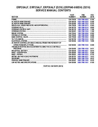
  • 1. ERP20ALF, ERP25ALF, ERP30ALF (D216) (ERP040-060DH) (D216) SERVICE MANUAL CONTENTS SECTION PART NUMBER YRM NUMBER REV DATE FRAME............................................................................................................................ 524179935 0100 YRM 0582 07/05 DC MOTOR MAINTENANCE.......................................................................................... 524158039 0620 YRM 0294 03/08 AC MOTOR MAINTENANCE.......................................................................................... 524183080 0620 YRM 1053 03/10 DRIVE AXLE, SPEED REDUCER, AND DIFFERENTIAL............................................. 524179938 1400 YRM 0575 03/03 STEERING AXLE............................................................................................................ 524158752 1600 YRM 0316 08/06 STEERING CONTROL UNIT.......................................................................................... 524158753 1600 YRM 0720 11/06 STEERING SYSTEM...................................................................................................... 524183081 1600 YRM 1054 11/06 BRAKE SYSTEM............................................................................................................ 524179943 1800 YRM 0566 03/03 HYDRAULIC SYSTEM.................................................................................................... 524179945 1900 YRM 0559 04/09 MAIN CONTROL VALVE................................................................................................ 524179946 2000 YRM 0562 02/09 TILT CYLINDERS........................................................................................................... 524150790 2100 YRM 0103 03/07 ELECTRICAL SYSTEM.................................................................................................. 524183082 2200 YRM 1055 10/09 AC MOTOR CONTROLLER DESC/CHKS/ADJ/TRBSHT/REP&THEORY OF OPERATION/DISPLAY PANEL................................................................................. 524183083 2200 YRM 1056 03/09 TROUBLESHOOTING AND ADJUSTMENTS USING THE AC CONTROLS PROGRAM................................................................................................................. 524183085 2200 YRM 1058 04/11 INDUSTRIAL BATTERY................................................................................................. 524158040 2240 YRM 0001 09/14 MAST - DESCRIPTION................................................................................................... 524158890 4000 YRM 0521 03/06 MAST - REPAIR.............................................................................................................. 524158891 4000 YRM 0522 07/10 METRIC AND INCH (SAE) FASTENERS....................................................................... 524150797 8000 YRM 0231 10/13 DIAGRAMS..................................................................................................................... 524183086 8000 YRM 1059 08/12 PERIODIC MAINTENANCE............................................................................................ 524183087 8000 YRM 1060 02/10 CAPACITIES AND SPECIFICATIONS........................................................................... 524183088 8000 YRM 1061 01/05 PART NO. 524183079 (09/14)
  • 2. 100 YRM 582 Description General This section has a description and the service procedures for the parts of the frame. These parts include the frame, counterweight assembly, overhead guard, hood and seat assembly, access panels, and label positions. The proce- dure for removing the traction motor is also described in this section. Description MAIN FRAME The main frame is a single weldment. See Figure 1. The main frame has mounts for the following: • Counterweight • Overhead guard, • Battery restraint and hood • Tilt cylinders • Steering axle • Drive axle assembly • Cowl assembly • Floor pedals and floor plates • Side step and fender weldments • Hydraulic tank • Pump and motor assemblies (steer, lift, and traction motors) • Control valves, and the levers The hood is part of the operator and battery restraint system. The seat is part of the operator restraint sys- tem. The floor plates can be removed for access to the traction motor. The panels on the sides of the bat- tery compartment can also be easily removed. The hy- draulic tank, lift pump motor assembly, and the steer- ing pump motor assembly are in a compartment be- tween the battery and the counterweight. The SCR (silicon controlled rectifier) or transistor electronic con- trollers and contactors are in the top of the counter- weight. The top cover of the counterweight can be re- moved for access to the controllers and contactors for early model ERP20-30ALF (B216) lift trucks. See Fig- ure 2. The rear cover of the counterweight can be re- moved for access to the controllers and contactors for later model ERP20-30ALF (B216) trucks and ERP20- 30ALF (ERP040-060DH) (D216) trucks. See Figure 3. There are two main frames for lift trucks made for use in North America and two main frames for lift trucks made for use in Europe. The frames are different because of the different battery compartment sizes. There are two battery compartment lengths. The battery com- partment widths are also different for Europe and North America. See Battery Specifications, at the back of this manual. WARNING The battery must fit the battery compartment so that the battery restraint will operate correctly. A loose battery can cause serious injury and property damage if the lift truck overturns. Adjust the spacer plate to prevent the battery from moving more than 13 mm (0.5 in.) forward or backward. WARNING Maximum clearance between the battery and bat- tery compartment width is 13 mm (0.5 in.). Maxi- mum clearance between the battery and the spacer plate is also 13 mm (0.5 in.). The Battery Specifica- tions chart shows the minimum size compartment allowed. The weight of the battery is a large part of the coun- terweight system on an electric lift truck. Make sure that the battery is within the weight limits indicated on the nameplate. Each model of lift truck has a cast-iron counterweight that provides the additional weight nec- essary for the indicated capacity. OTHER FRAME WELDMENTS These frame parts are the right-hand and left-hand side step and fender weldments, and the cowl weldment. See Figure 1. Each part is a weldment fastened to the main frame to make the frame assembly. The cowl weldment is a mount for the front of the overhead guard (see Figure 2 and Figure 3), the steering column as- sembly (see Figure 4, Figure 5, and Figure 6), the re- lease linkage of the parking brake, and the instrument panel with light switches. The display panels for these models of lift trucks are mounted into the instrument panel. See Figure 4, Figure 5, and Figure 6. 1
  • 3. Description 100 YRM 582 1. COWL 2. BATTERY SPACER PLATE 3. BATTERY RETAINER ROD 4. FRAME 5. SIDE STEP AND FENDER WELDMENT 6. ACCESS PANEL 7. FLOOR PLATES Figure 1. Lift Truck Main Frame Legend for Figure 2 1. OVERHEAD GUARD 2. COVER OF ELECTRONICS COMPARTMENT 3. COUNTERWEIGHT 4. TOW PIN AND HANDLE 5. CAPSCREW 6. LOCKWASHER 7. WASHER 8. HANDLE 9. SCREW 10. NUT 11. FOAM TAPE 2
  • 4. 100 YRM 582 Description Figure 2. Overhead Guard and Counterweight Early Model ERP20-30ALF (B216) Trucks 3
  • 5. Description 100 YRM 582 OVERHEAD GUARD WARNING Do not operate the lift truck without the overhead guard and cowl correctly fastened to the lift truck. The overhead guard is a weldment that fastens to the main frame and cowl to help protect the operator from falling objects. For early model ERP20-30ALF (B216), see Figure 2. For later model ERP20-30ALF (B216) and ERP20-30ALF (ERP040-060DH) (D216) trucks, see Figure 3. A slot in the overhead guard permits removal of the battery without removing the overhead guard. Legend for Figure 3 A. OVERHEAD GUARD USED ON LATER MODEL ERP20-30ALF (B216) TRUCKS B. OVERHEAD GUARD USED ON ERP20-30ALF (ERP040-060DH) (D216) TRUCKS 1. OVERHEAD GUARD 2. HANDLE 3. ROLLING THREAD SCREW 4. NUT 5. WASHER 6. CAPSCREW 7. COVER 8. TOW PIN 9. TAPE 10. COVER 11. SOCKET CAPSCREW 12. LOCKWASHER 13. COUNTERWEIGHT 14. FOAM TAPE 15. SPACER 16. BRACKET 17. SELF RETAINING NUT 4
  • 6. 100 YRM 582 Description Figure 3. Overhead Guard and Counterweight Later Model ERP20-30ALF (B216) Trucks and ERP20-30ALF (ERP040-060DH) (D216) Trucks 5
  • 7. Description 100 YRM 582 A. CURTIS METER B. GE METER (OPTIONAL) C. STEERING CONTROL UNIT USED ON EARLY MODEL LIFT TRUCKS D. STEERING CONTROL UNIT USED ON LATER MODEL LIFT TRUCKS 1. STEERING WHEEL 2. STEERING CONTROL UNIT 3. LATCH MECHANISM 4. COLUMN COVER 5. COLUMN FRAME 6. HORN SWITCH CONNECTOR 7. ON-DEMAND STEERING COMPONENTS (NOT ALL UNITS) 8. OPTIONAL BASIC DISPLAY PANEL 9. STANDARD DISPLAY PANEL (WITH CURTIS OR GE METER) 10. PREMIUM DISPLAY PANEL 11. HORN BUTTON 12. STEERING COLUMN 13. STEERING COLUMN NUT Figure 4. Steering Column and Instrument Panel Early Model ERP20-30ALF (B216) Lift Trucks 6
  • 8. 100 YRM 582 Description 1. STEERING WHEEL 2. SHIFT LEVER MECHANISM 3. COLUMN COVER 4. STEERING CONTROL UNIT 5. COLUMN FRAME 6. ON-DEMAND STEERING COMPONENTS 7. DISPLAY PANEL (PREMIUM DISPLAY PANEL SHOWN) 8. LATCH MECHANISM 9. HORN SWITCH CONNECTOR 10. HORN BUTTON 11. STEERING COLUMN 12. STEERING COLUMN NUT Figure 5. Steering Column and Display Panel, Later Model ERP20-30ALF (B216) Trucks 7
  • 9. Description 100 YRM 582 Figure 6. Steering Column and Display Panel, ERP20-30ALF (ERP040-060DH) (D216) Trucks 8
  • 10. 100 YRM 582 Description Legend for Figure 6 1. ON-DEMAND STEERING COMPONENTS 2. SHIFT LEVER MECHANISM 3. STEERING WHEEL 4. DISPLAY PANEL 5. COLUMN COVER 6. COLUMN FRAME 7. STEERING CONTROL UNIT 8. COWL WELDMENT 9. DASH 10. COLUMN MOUNT 11. LATCH MECHANISM 12. HORN SWITCH CONNECTOR 13. HORN BUTTON 14. STEERING COLUMN 15. STEERING COLUMN NUT BATTERY AND OPERATOR RESTRAINT, HOOD, AND SEAT ASSEMBLY Battery Restraint WARNING The hood and battery restraint, as well as the latch for the hand lever assembly, must operate correctly before a lift truck is operated. These parts are part of the battery restraint system. The battery restraint system must operate correctly to help provide rea- sonable protection to the operator if the lift truck tips over. A battery restraint system is installed as a safety device. See Figure 7. The function on the battery restraint sys- tem is to hold the battery in the battery compartment in case of a tip over. Part of the battery restraint system is a battery restraint rod at the rear of the battery com- partment. See Figure 7. This restraint rod extends over the rear edge of the battery case to help hold the bat- tery within the battery compartment during a tip over. A handle is used to move the restraint rod. The handle of the battery restraint must be in the DOWN position to close the hood. The handle can be moved to the DOWN position only after the restraint rod is extended over the battery. The restraint rod can only be retracted when the hood is in the UP position. WARNING The battery must fit the battery compartment so that the battery restraint will operate correctly. A loose battery can cause serious injury and property damage if the lift truck overturns. The battery must not be able to move more than 13 mm (0.5 in.) for- ward, backward, or side to side. An adjustable spacer plate is used at the front of the battery compartment to prevent forward and backward movement of the battery. See Figure 8. The adjustable spacer plate is used inside the battery compartment. See Figure 8. The spacer plate must be adjusted for a maximum clearance of 13 mm (0.5 in.) with the bat- tery against the rear bulkhead. There must be some clearance to allow battery removal. See the section Periodic Maintenance 8000 YRM 552 for both early and later model ERP20-30ALF (B216) trucks and Peri- odic Maintenance 8000 YRM 1060, for ERP20-30ALF (ERP040-060DH) (D216) models, to remove the battery and adjust the spacer plate. A. RETRACTED B. EXTENDED 1. BATTERY RESTRAINT WARNING LABEL 2. HOOD 3. BATTERY RESTRAINT HANDLE 4. BATTERY 5. STEEL WELDMENT Figure 7. Battery Restraint Rod 9
  • 11. Description 100 YRM 582 1. BATTERY COMPARTMENT 2. BATTERY 3. BULKHEAD 4. SPACER PLATE 5. ADJUSTMENT CAPSCREW 6. JAM NUTS Figure 8. Battery Spacer Plate Hood WARNING The gas springs for the hood can raise the hood at a rapid rate and cause an injury. DO NOT get over hood when raising hood. WARNING The batteries for these lift trucks must fit the bat- tery compartment width with a maximum of 13 mm (0.5 in.) clearance. The Battery Specifications at the back of this manual, shows the minimum sizes of the battery compartments. Another important part of the battery restraint system is the steel weldment that is also the hood frame. See Figure 7. This hood frame is connected to the lift truck frame with hinges at the rear of the hood (see Fig- ure 13). The front of the hood and frame is locked in the closed position by the assembly for the hydraulic hand levers. A latch releases the assembly to tilt forward and allow the hood to raise. See Figure 9. Gas springs help lift the hood assembly. The seat and other parts of the operator restraint system fasten to the hood assembly. A. CLOSED OVER HOOD B. OPEN 1. HAND LEVER ASSEMBLY 2. HOOD 3. SEAT 4. LATCH HANDLE 5. LATCH Figure 9. Hood and Hand Lever Assembly with Latch 10
  • 12. 100 YRM 582 Overhead Guard Replacement Operator Restraint System and Seat Assembly The operator restraint system has the seat, hip re- straints, and the seat belt. The system helps the operator stay within the lift truck in case of a tip over. See Figure 10. Make sure that the seat is not loose on the rails. Make sure the seat rails are not loose. The seat rails must lock securely in position, but move freely when unlocked. The seat rails must be securely attached to the mount- ing surface. Legend for Figure 10 1. SEAT 2. HIP RESTRAINT 3. SEAT BELT AND MOUNT 4. SEAT RAILS 5. CAPSCREW Figure 10. Seat Assembly and Operator Restraint Overhead Guard Replacement REMOVE WARNING Do not weld, drill, grind, or cut the overhead guard for mounts of lights or accessories. The strength of the overhead guard can be reduced. 1. Remove the battery as described in the section Pe- riodic Maintenance 8000 YRM 552 for both early and later ERP20-30ALF (B216) model lift trucks and Periodic Maintenance 8000 YRM 1060 for ERP20-30ALF (ERP040-060DH) (D216) lift truck models. 2. Access to the capscrews that hold the rear legs of the overhead guard to the frame is from the battery compartment. See Figure 11 and Figure 12. Re- move the capscrews, washers, and nuts that fasten each leg. 3. Remove the capscrews, washers, and nuts that hold each front leg of the overhead guard to the cowl. Disconnect any electric wires from under the cowl that go through the front legs of the overhead guard. When the overhead guard is lifted from the frame, make sure these electric wires move through the holes in the frame at the front and rear so that they are not damaged. 4. Use a lifting device or another person to help lift the overhead guard from the lift truck. INSTALL Put the overhead guard on the lift truck. Install any electric wires from the overhead guard legs through the holes in the frame. Install the capscrews, washers, and nuts that hold each front leg to the frame. See Figure 11 and Figure 12. Tighten the capscrews to 102 N•m (75 lbf ft). Install the capscrews, washers, and nuts that hold the rear legs to the frame. Tighten the capscrews to 102 N•m (75 lbf ft). Install the battery as described in the section Periodic Maintenance 8000 YRM 552 for both early and later ERP20-30ALF (B216) model lift trucks and Periodic Maintenance 8000 YRM 1060 for ERP20-30ALF (ERP040-060DH) (D216) lift truck models. 11
  • 13. Overhead Guard Replacement 100 YRM 582 Figure 11. Overhead Guard and Counterweight Early Model ERP20-30ALF (B216) Trucks 12
  • 14. 100 YRM 582 Overhead Guard Replacement Legend for Figure 11 1. OVERHEAD GUARD 2. COVER OF ELECTRONICS COMPARTMENT 3. COUNTERWEIGHT 4. TOW PIN AND HANDLE 5. CAPSCREW 6. LOCKWASHER 7. WASHER 8. HANDLE 9. SCREW 10. NUT 11. NUT 12. FOAM TAPE 13
  • 15. Overhead Guard Replacement 100 YRM 582 Figure 12. Overhead Guard and Counterweight Later Model ERP20-30ALF (B216) Trucks and ERP20-30ALF (ERP040-060DH) (D216) Trucks 14
  • 16. 100 YRM 582 Hood, Seat Assembly and Operator Restraint Replacement Legend for Figure 12 A. OVERHEAD GUARD USED ON LATER MODEL ERP20-30ALF (B216) TRUCKS B. OVERHEAD GUARD USED ON ERP20-30ALF (ERP040-060DH) (D216) TRUCKS 1. OVERHEAD GUARD 2. HANDLE 3. ROLLING THREAD SCREW 4. NUT 5. WASHER 6. CAPSCREW 7. COVER 8. TOW PIN 9. TAPE 10. COVER 11. SOCKET CAPSCREW 12. LOCKWASHER 13. COUNTERWEIGHT 14. FOAM TAPE 15. SPACER 16. BRACKET 17. SELF RETAINING NUT Hood, Seat Assembly and Operator Restraint Replacement HOOD AND SEAT ASSEMBLY Remove WARNING The gas spring for the hood can raise the hood at a rapid rate and cause an injury. DO NOT get over hood when raising hood. NOTE: The hood and seat assembly can be removed as a unit or the seat assembly can be removed with the hood assembly installed on the truck frame. Do only the steps necessary. If the hood and seat assembly will be removed as a unit, do Step 1 through Step 4. To remove the seat assembly from the hood assembly, do Step 1 through Step 3 and Step 5 through Step 7. Remove the hood and seat assembly as follows (see Figure 13): 1. Turn the key to the OFF position and remove the key. WARNING Never put tools or other metal on the battery. Metal on the battery can cause a short circuit and possi- ble damage or injury. 2. Open the hood and disconnect the battery connec- tor. Install a cardboard or plywood cover on the top of the battery to prevent accidental short circuits. 3. Disconnect the connector for the seat switch wires near the rear of the hood frame. If the hood will be removed, remove the Emergency Stop knob and the power disconnect assembly from the hood. 4. Fasten the hood assembly so that it cannot lower and carefully remove the gas springs from the hood. Have an assistant help hold the hood assembly. Remove the screws that fasten the hood assembly to the lift truck frame. See Figure 13 and Figure 14. Carefully remove the hood assembly. 5. Push the connector of the seat switch wire through the grommet in the hood. It can be necessary to remove the grommet from the hole in the hood for enough clearance to get the connector through the grommet. Inspect seat switch and replace if worn or damaged. See Figure 13 6. Remove the screws that fasten the seat to the hood and hood frame. Close and latch the hood and put the seat on its side for access to the seat switch. 7. Use a flat blade screwdriver or other tool with a flat blade to carefully lift the switch free of the seat pan. Slide the switch out of the seat cushion. 15
  • 17. Hood, Seat Assembly and Operator Restraint Replacement 100 YRM 582 Figure 13. Hood Remove 16
  • 18. 100 YRM 582 Hood, Seat Assembly and Operator Restraint Replacement Legend for Figure 13 A. TOP VIEW B. SIDE VIEW C. HOOD IN OPEN POSITION 1. HOOD HANDLE 2. EMERGENCY STOP BUTTON 3. HOOD 4. SEAT SWITCH 5. GAS SPRING 6. SEAT 7. SEAT RAILS 8. HOOD BRACKET SPRING 9. CAPSCREW, WASHER, AND NUT 10. WASHER, NUT, AND BOLT 11. BATTERY COVER 12. OVERHEAD GUARD Install NOTE: If just the seat assembly was removed, install seat assembly onto hood by performing Step 1, Step 2, Step 4, and Step 5. If the hood and seat assembly were removed, install hood and seat assembly by performing Step 3 through Step 5. 1. Carefully slide the seat switch into the cavity of the seat cushion until the end of the switch with the wires is aligned over the hole in the pan. Push on the switch until the clips of the switch are fastened to the seat. See Figure 13. 2. Carefully install the grommet over the wire connec- tor (see Figure 14.) Install the seat on the hood and tighten the nuts. Install the grommet in the hole of the hood, connect the wire connector, and push the connector back inside the hood frame. 3. If the hood assembly was removed, have an assis- tant help align the hood assembly in the correct po- sition. Install the screws that fasten the hood as- sembly to the lift truck frame. See Figure 13. Hold the hood assembly in the open position and care- fully install the gas springs. 4. Install the power disconnect assembly on the hood. Install the Emergency Stop knob. 5. Remove cardboard or plywood from top of battery. 17
  • 19. Hood, Seat Assembly and Operator Restraint Replacement 100 YRM 582 1. HOOD 2. STEEL WELDMENT 3. PLATE 4. WASHER 5. LOCKWASHER 6. NUT 7. GAS SPRING 8. FOAM TAPE 9. SPACER 10. BRACKET 11. CAPSCREW 12. TRIM 13. COVER 14. RIVET 15. HANDLE 16. STRAP CLAMP 17. CLIP 18. INSULATION 19. BOLT 20. GROMMET Figure 14. Hood Assembly 18
  • 20. 100 YRM 582 Counterweight Replacement OPERATOR RESTRAINT SYSTEM The parts of the operator restraint system are as fol- lows: the seat belt, hip restraint brackets, seat and mounting, battery restraint (restraint rod and hood plate), and the assembly for the hydraulic hand levers and latch. See Figure 13 and Figure 15. Each item must be checked to make sure it is attached securely, functions correctly, and is in good condition. The seat belt must latch securely. Make sure the seat belt extends and retracts smoothly and is not damaged or torn. If the seat belt cannot be pulled from the retrac- tor assembly, the seat belt assembly must be replaced. 1. SEAT 2. HIP RESTRAINT 3. SEAT BELT AND MOUNT 4. SEAT RAILS 5. CAPSCREW Figure 15. Operator Restraint and Seat Assembly Counterweight Replacement If the lift truck must be put on blocks for maintenance and repair, see the section Periodic Maintenance 8000 YRM 552 for early and later model ERP20-30ALF (B216) trucks and Periodic Maintenance 8000 YRM 1060 for ERP20-30ALF (ERP040-060DH) (D216) mod- els, for the procedures of putting the lift truck on blocks. WARNING The counterweight is very heavy. Make sure that the crane and lifting devices have enough lifting capac- ity to safely lift the counterweight. The weights of the counterweights are shown in Table 1. The counterweight normally is not removed for most re- pairs. The counterweight is fastened to the frame with four capscrews. The weights for the counterweights are shown in Table 1. REMOVE NOTE: For early model ERP20-30ALF (B216) lift trucks, do Step 1 through Step 4 and Step 6 and Step 7. For later model ERP20-30ALF (B216) lift trucks and for ERP20-30ALF (ERP040-060DH) (D216) lift trucks, do Step 1 and Step 5 through Step 7. 1. Remove the battery. See the section Periodic Maintenance 8000 YRM 552 for ERP20-30ALF (B216) models and Periodic Maintenance 8000 YRM 1060 for ERP20-30ALF (ERP040-060DH) (D216) models, for the procedures to remove the battery. 2. Remove the top cover of the counterweight (cover over electronics compartment). See Figure 11. 19
  • 21. Counterweight Replacement 100 YRM 582 Table 1. Counterweights Model (mm*) Weight +50 kg (110 lb) 0 kg (0 lb) ERP20ALF and ERP25ALF (B216), ERP20ALF and ERP25ALF (ERP040DH and ERP050DH) (D216) 717 mm ERP25ALF and ERP30ALF (B216), ERP25ALF and ERP30ALF (ERP50DH and ERP60DH) (D216) 861 mm 685 kg (1510 lb) ERP30ALF (B216) and ERP30ALF (ERP060DH) (D216) 861 mm 750 kg (1653 lb) *Approximate battery compartment lengths. WARNING Do not touch the terminals of capacitor C1 of the traction or lift motor SCR controllers. The charge on the capacitors can cause electrical shock and personal injury. Disconnect the battery and use an insulated screwdriver or jumper wire to make a short circuit across the capacitor terminals. The short circuit will discharge each capacitor and pre- vent electrical shocks. 3. Remove the three capscrews that fasten the motor controllers to the counterweight. See Figure 16. Carefully lift the controller assembly up to a nearly vertical position. Use cord or wire fastened to the overhead guard to hold the controller assembly in this vertical position. 1. COUNTERWEIGHT 2. CAPSCREWS Figure 16. Remove Motor Controllers, ERP30ALF (B216) Models Only 20
  • 22. 100 YRM 582 Counterweight Replacement 4. Install a lifting eye in the hole at the top rear of the counterweight. Use a lifting eye [shaft length approximately 200 mm (8 in.)] with a washer and nut. Fasten a sling or chain to the lifting eye. Make sure the chain or sling and crane has the capacity to lift the counterweight. See Table 1. Raise the crane to make sure the crane is the support for the weight of the counterweight. 5. Remove the top cover on the counterweight and the cover in the front part of the counterweight that cov- ers the electronic control compartment. See Fig- ure 12. Fasten a sling or chain around the counter- weight. Make sure the chain or sling and crane has the capacity to lift the counterweight. See Table 1. 6. From inside the battery compartment near the bottom, remove the two top capscrews that hold the counterweight to the frame. Remove the capscrews, nuts, and washers that fasten the counterweight between the wheels under the tow pin. Use the crane to lift the counterweight away from the lift truck frame. On Later Model ERP20-30ALF (B216) Trucks and ERP20-30ALF (ERP040-060DH) (D216) Model Trucks, make sure that you do not damage the motor controller assembly. 7. Put the counterweight in a position so that it cannot fall and cause damage or in injury. INSTALL, EARLY MODEL ERP20-30ALF (B216) LIFT TRUCKS 1. Use a crane and a lifting eye to lift the counter- weight into position at the rear of the truck. Make sure that you do not damage the motor controller assembly during installation. See Figure 11. In- stall the two upper capscrews near the bottom of the battery compartment that hold the counterweight to the frame. Install the lower capscrews, washers, and nuts in the tow pin area of the counterweight. Tighten the upper capscrews to 320 N•m (236 lbf ft). Tighten the lower (between wheels) capscrews and nuts to 66 N•m (49 lbf ft). If removed, tighten the cover capscrews to 52 N•m (38 lbf ft). NOTE: The top cover of the counterweight can be re- moved from the counterweight to make checks and ad- justments on the controller. 2. Disconnect the sling or chain. Remove the lifting eye from the counterweight and install the motor controller assembly (see Figure 16). Install the top cover on the counterweight. 3. Install the battery. See the section How to Change Battery in Periodic Maintenance 8000 YRM 552. INSTALL, LATER MODEL ERP20-30ALF (B216) TRUCKS AND ERP20-30ALF (ERP040-060DH) (D216) MODEL TRUCKS 1. Use a crane and either a sling or chain to lift the counterweight into position at the rear of the truck. See Figure 12. Install the two upper capscrews near the bottom of the battery compartment that hold the counterweight to the frame. Install the lower capscrews, washers, and nuts in the tow pin area of the counterweight. Tighten the upper cap- screws to 320 N•m (236 lbf ft). Tighten the lower (between wheels) capscrews and nuts to 66 N•m (49 lbf ft). If removed, tighten the cover capscrews to 52 N•m (38 lbf ft). 2. Disconnect the sling or chain. Install the top cover and the electronic control compartment cover, on the front of the counterweight. 3. Install the battery. See the section Periodic Maintenance 8000 YRM 552 for later model ERP20-30ALF (B216) trucks and Periodic Main- tenance 8000 YRM 1060 for ERP20-30ALF (ERP040-060DH) (D216) models, for the proce- dures to install the battery. 21
  • 23. Traction Motor Replacement 100 YRM 582 Traction Motor Replacement REMOVE This procedure will show the removal of the traction mo- tor from the speed reducer with the drive train installed in the lift truck. See Figure 17, Figure 18, and Figure 19. For repair procedures to the traction motor, see the section DC Motor Maintenance 620 YRM 294 for all lift truck models or the section AC Motor Repair 620 YRM 1053 for lift truck models ERP20-30ALF (ERP040- 060DH) (D216). NOTE: The traction motor can be removed separately or as a unit with the drive train. Removal with the drive train requires the use of a floor jack and is more difficult. The lift truck must be on blocks with clearance for the jack and traction motor to be removed as a unit. The hydraulic lines from the hydraulic tank must also be dis- connected if this method is used. Remove the traction motor from the speed reducer and lift truck as follows (see Figure 17): 1. Put the lift truck on blocks for easier access to the bottom bolts between the traction motor and the speed reducer. 2. Disconnect the battery connector and remove the key from the key switch. Remove the floor plates. NOTE: It is not necessary to disconnect the hydraulic line from the master cylinder to remove the traction mo- tor. If the hydraulic line is not disconnected, it will not be necessary to remove air from the brake system after installation. The master cylinder has a cap that does not leak, so it is not necessary to remove the reservoir. 3. During the removal of the following items, make sure to install plugs in hydraulic lines that are dis- connected. Install a tag on all wires or cables for correct connection during installation. Do not dis- assemble the pedal assemblies any more than nec- essary for clearance to remove the traction motor. This will prevent having to make adjustments after installation. Remove the following components or fasten them in a position for clearance to remove the traction motor: • Horn • Foot Directional Control Pedal or Accelerator Pedal Assembly • Brake Pedal Assembly with Master Cylinder and Hydraulic Line • Parking Brake Pedal Assembly • Two Hydraulic Lines for Steering System that are Over Traction Motor • Power Cables and Sensor Wires of Traction Motor 4. Remove the bottom bolts that fasten the speed re- ducer and the motor. Make an alignment mark on the traction motor and the speed reducer case for correct installation. 5. Install a lifting eye in the hole in the top of the mo- tor. The hole has M10 × 1.5 mm threads and is near the center of the motor on top. Connect a special lifting device or chain (for a crane) to the lifting eye to hold the traction motor. See Figure 18 or Fig- ure 19. Use a special lifting device fastened to the overhead guard or use a crane to hold the weight of the traction motor. NOTE: The traction motors are in different configura- tions for different applications of the lift trucks. Trac- tion motors weigh approximately 90 to 140 kg (200 to 310 lb). 6. Remove all the other bolts that fasten the speed reducer and the motor. Pull the traction motor from the speed reducer. See Figure 18 or Figure 19. 7. Use the crane to move the traction motor to a space to make repairs. 22
  • 24. 100 YRM 582 Traction Motor Replacement A. TOP VIEW, EARLY AND LATER MODEL ERP20-30ALF (B216) TRUCKS B. TOP VIEW, ERP20-30ALF (ERP040-060DH) (D216) MODELS C. SIDE VIEW, EARLY AND LATER MODEL ERP20-30ALF (B216) TRUCKS D. SIDE VIEW, ERP20-30ALF (ERP040-060DH) (D216) MODELS 1. TRANSMISSION AND DIFFERENTIAL 2. TRACTION MOTOR 3. CAPSCREW, NUT, AND WASHER 4. TRACTION MOTOR MOUNTING PLATE (TO TRANSMISSION AND DIFFERENTIAL) 5. TRUCK FRAME 6. CAPSCREW, NUT, AND WASHER 7. PIN 8. CAPSCREW, WASHER, AND LOCK NUT 9. DRIVE AXLE 10. SPEED REDUCER Figure 17. Remove and Install Traction Motor 23
  • 25. Hydraulic Tank Repair 100 YRM 582 1. TRACTION MOTOR 2. LIFTING EYE 3. SLING Figure 18. Lift Traction Motor From Truck, Early and Later Model ERP20-30ALF (B216) Trucks 1. TRACTION MOTOR 2. LIFTING EYE 3. SLING Figure 19. Lift Traction Motor From Truck, ERP20-30ALF (ERP040-060DH) (D216) INSTALL 1. Install a lifting eye in the hole in the top of the motor. Use a special lifting device fastened to the overhead guard or a chain and crane to lift the motor. See Figure 18 or Figure 19. 2. Lower the traction motor into position in the lift truck. Align the traction motor with the speed reducer. See Figure 17. Align the alignment marks made during removal. NOTE: If a different traction motor is being installed, it can be necessary to adjust the capscrew that is be- tween the housing for the speed reducer/differential and the bottom of the traction motor. 3. Use a board or pry bar if necessary to push the traction motor into the speed reducer. 4. Align the bolt holes in the speed reducer and the motor housing. Install the bolts that hold the traction motor to the speed reducer. Tighten the bolts to 38 N•m (28 lbf ft). See Figure 17. 5. Remove the lifting device and, if necessary, adjust the support capscrew. Loosen the jam nut and ad- just the capscrew until the head just touches the traction motor. Turn the capscrew an additional 1/2 turn counterclockwise to push on the traction mo- tor. Tighten the jam nut to 33 N•m (24 lbf ft) without moving the capscrew. Remove the lifting eye. 6. Install all power cables, wires, hydraulic lines, and pedal assemblies as removed. Fill the cavity of pivot for the parking and service brake pedals with multipurpose grease during installation. Remove the air from the brake system as described in the section the Brake System 1800 YRM 566. 7. Operate the steering system and check for leaks. Repair any leaks. Install all panels, covers, and floor plates. Hydraulic Tank Repair REMOVE 1. Turn the key to the OFF position and remove the key. WARNING Never put tools or other metal on the battery. Metal on the battery can cause a short circuit and possi- ble damage or injury. 2. Open the hood and install a cardboard or plywood cover on the top of the battery to prevent accidental short circuits. 3. Turn the steering wheel for a full left turn for ac- cess to the drain plug near the front of the right rear wheel. See Figure 20. Install a container under the drain plug of the hydraulic tank with a capacity of 27.4 liter (7.25 gal). 4. Remove the drain plug and let the oil drain from the hydraulic tank. Install and tighten the drain plug. 5. Remove and install plugs in all the hoses fastened to the hydraulic tank. Remove the breather/dipstick/ fill cap and install a plug in the opening of the fill tube. 24
  • 26. 100 YRM 582 Hydraulic Tank Repair 6. Remove the screws from the bracket that fastens the bracket holding the hydraulic tank in the truck frame. See mount bracket assembly of Figure 20. Remove the bracket assembly. 7. Carefully lift the hydraulic tank up out of the frame. 1. HYDRAULIC TANK 2. FILTER 3. MOUNT BRACKET ASSEMBLY 4. FILL CAP/BREATHER/DIPSTICK 5. RETURN TO TANK 6. RETURN FROM SYSTEM 7. DRAIN PLUG 8. LIFT PUMP SUPPLY PORT 9. STEERING PUMP SUPPLY PORT Figure 20. Hydraulic Tank Assembly INSPECT WARNING Special procedures must be followed when large leaks or other repairs need welding or cutting. All work must be done by authorized personnel. If the tank is cleaned inside of a building, make sure there is enough ventilation. See the following manuals for additional information: • Safe Practices for Welding and Cutting Contain- ers That Have Held Combustibles by the Ameri- can Welding Society, F4.1 - 1999. • Safety In Welding and Cutting, American National Standard, AWS Z 49.1 - 1999. WARNING Do not use tools that can make sparks, heat, or static electricity. The vapors in the tank can cause an explosion. CAUTION Additives may damage the hydraulic system. Be- fore using additives, contact your local Yale dealer. Make a visual inspection of all sides of the tank. Inspect the welds for cracks and leakage. Check for wet areas, accumulation of dirt, and loose or missing paint caused by leakage. Areas of the tank that are not easily seen can be checked with an inspection mirror and a light that is approved for locations with flammable vapors. The hydraulic tank is a separate sheet metal tank and can be removed from the lift truck if necessary to check for leaks or for replacement. Repairs for leaks in the hy- draulic tank can require special procedures described in the next paragraphs. The most common cause of leaks is from rust caused by the moisture of condensation or a plugged hydraulic tank breather. Drain any water out of the tank by removing the drain plug and letting the tank drain until there is no water in the oil. CLEAN WARNING When cleaning the tank, do not use solutions that make dangerous gases at normal temperatures or when heated. Wear eye and face protection. Protect the body from burns. WARNING Do not use tools that can make sparks, heat, or static electricity. The vapors in the tank can cause an explosion. When cleaning the tank, do not use solutions that make dangerous gases at normal temperatures or when heated. Wear eye and face protection. Protect the body from burns. 25
  • 27. Hydraulic Tank Repair 100 YRM 582 Steam Method When cleaning with steam, use a hose with a minimum diameter of 19 mm (0.75 in.). Control the pressure of the steam by a valve installed at the nozzle of the hose. If a metal nozzle is used, it must be made of a material that does not make sparks. Make an electrical connec- tion between the nozzle and the tank. Connect a ground wire to the tank to prevent static electricity. Use the following procedure to clean the tank with steam: 1. Remove all the parts from the tank. Install the drain plug. 2. Fill the tank 1/4 full with a solution of water and sodium bicarbonate (baking soda) or sodium car- bonate. Mix 0.5 kg (1 lb) per 4 liter (1 gal) of water. WARNING Compressed air can move particles so that they cause injury to the user or to other personnel. Make sure that the path of the compressed air is away from all personnel. Wear protective goggles or a face shield to prevent injury to the eyes. 3. Mix the solution in the tank using air pressure. Make sure all the surfaces on the inside of the tank are flushed with the solution. Drain the tank. 4. Put steam into the tank until the tank does not have odors and the metal is hot. Steam vapors must come from all the openings. 5. Flush the inside of the tank with boiling water. Make sure all the loose material is removed from the in- side of the tank. 6. Make an inspection of the inside of the tank. If it is not clean, repeat Step 4 and Step 5 and make another inspection. When making inspections, use a light that is approved for locations with flammable vapors. 7. Put plugs in all the openings in the tank. Wait 15 minutes, then remove the inlet and outlet plugs. Test a sample of the vapor with a special indicator for gas vapors. If the amount of flammable vapors is above the lower flammable limit, repeat the clean- ing procedures. Chemical Solution Method If the tank cannot be cleaned with steam, use the fol- lowing procedure: 1. Mix a solution of water and trisodium phosphate or a cleaning compound with an alkali base. Follow the instructions given by the manufacturer. WARNING Compressed air can move particles so that they cause injury to the user or to other personnel. Make sure that the path of the compressed air is away from all personnel. Wear protective goggles or a face shield to prevent injury to the eyes. 2. Fill the tank with the cleaning solution. Use com- pressed air to mix the solution in the tank. 3. Drain the tank. Flush the inside of the tank with hot (boiling) water. Make sure all the cleaning com- pound is removed. 4. Make an inspection of the inside of the tank. If the tank is not clean, repeat Step 1 through Step 3. Make another inspection of the tank. When mak- ing inspections, use a light that is approved for lo- cations with flammable vapors. 5. Check the tank for flammable vapors as described in the previous section Step 7. If the amount of flammable vapors is not below the lower flammable limit, repeat the cleaning procedures. ADDITIONAL PREPARATIONS FOR TANK REPAIR If nitrogen gas or carbon dioxide gas is available, pre- pare the tank for welding using these gases. See the manual Safe Practices For Welding and Cutting Con- tainers That Have Held Combustibles by the American Welding Society, F4.1 - 1999. If these gases are not available, another method using water can be used as follows: 1. Fill the tank with water to just below the point where the work will be done. Make sure the space above the level of the water has a vent. 2. Use acceptable welding practices to repair the tank. See the American National Standard "Safety in Welding and Cutting," AWS Z 49.1 - 1999. 26
  • 28. 100 YRM 582 Painting Instructions SMALL LEAKS, REPAIR Use the following procedure to seal small leaks: 1. Use steam to clean the area around the leak. Re- move all paint and dirt around the leak. WARNING Do not use tools that can make sparks, heat, or static electricity. The vapors in the tank can cause an explosion. 2. Apply Loctite® 290 to the leak. Follow the instruc- tions of the manufacturer. LARGE LEAKS, REPAIR 1. Use one of the procedures described under Clean, Steam Method of cleaning tank or Chemical Solu- tion Method of cleaning tank to clean and prepare the tank for repairs. 2. Use acceptable welding practices to repair the tank. See the American National Standard Safety In Welding and Cutting AWS Z 49.1 - 1999. PREPARATIONS FOR USAGE AFTER REPAIR 1. Add more water to the tank so that the water goes above the point of where the work was done. Check to see if there are any leaks coming from tank. 2. If there are no leaks coming from the tank, remove all the water from the tank. INSTALL 1. Turn the key to the OFF position and remove the key. WARNING Never put tools or other metal on the battery. Metal on the battery can cause a short circuit and possi- ble damage or injury. 2. Open the hood and install a cardboard or plywood cover on the top of the battery to prevent accidental short circuits. See Figure 20. 3. Carefully position the hydraulic tank over the correct position in the frame and install the hoses on the bottom of the tank. Lower the tank into the correct position in the frame. 4. Install the other hoses and if removed, the filter on the tank. Install the bracket that fastens the hy- draulic tank in the truck frame. See mount bracket assembly of Figure 20. 5. Fill the tank to the FULL mark on the dipstick and install the breather/dipstick/fill cap. 6. Operate the lift and steering systems and check for leaks. Painting Instructions WARNING Always use solvents and paints in an area with ventilation. Do not use solvents or paints near heat, fire, or electrical equipment that can make sparks. Follow the manufacturer’s instructions and Cautions. 1. Remove all dirt from the surface to be painted. Clean the area to be painted. Use a solvent for painted surfaces to remove grease and oil before sanding. Do not use solvent on new paint. Make sure all oil and grease is removed. 2. Use sandpaper to remove the top surface of the paint and rust from the metal. All metal surfaces where the paint is completely removed, must be painted. Use a primer. Apply the primer before applying the final coat of paint. 3. Protect all surfaces that will not be painted. See the list of items in Figure 21. CAUTION Do not paint the pads, plastic covers or knobs, cables, labels, and information plates or controls. Paint can make some assemblies not operate cor- rectly. 4. Paint the surfaces. Use the correct paint from your dealer for Yale lift trucks. Follow the directions on the container. The correct arrangement of colors is shown in Figure 21. 27
  • 29. Painting Instructions 100 YRM 582 WARNING Make sure all labels are installed after painting is complete. Safety labels are installed on the lift truck to give information about possible hazards. It is important that all safety labels are installed on the lift truck and can be read. 5. Check that all labels are installed in the correct lo- cations on the lift truck. See Figure 22. New labels are available from your dealer for Yale lift trucks. NOTE: USE COLORS APPROVED BY YALE CORPORATION. DO NOT PAINT THE FOLLOWING ITEMS: PEDAL PADS, LEVER KNOBS, INSTRUMENTS, STEERING WHEEL, SEAT ASSEMBLY AND SEAT RAILS, INFORMA- TION CASE AND COVER, TIRES, MAST CHAINS AND HOSES, ALL LABELS AND INFORMATION PLATES, BAT- TERY CONNECTOR, PARKING BRAKE HANDLE, KEY SWITCH, CYLINDER RODS, ALL PLASTIC COVERS, AND STEERING COLUMN COVER. NOTE: LIGHT AREAS = GOLD; DARK AREAS = BLACK; AND PARCHMENT = LOAD BACKREST, FORKS, AND WHEELS. Figure 21. Color Arrangement 28
  • 30. 100 YRM 582 Safety Label Replacement Safety Label Replacement WARNING Labels that have WARNINGS or CAUTIONS must be replaced if they are damaged. If a mast of a differ- ent size or an accessory carriage is installed, the capacity rating can change. Changes in the kind of drive tires can change the capacity rating. See a dealer for YALE lift trucks for a replacement name- plate. The nameplate information is a safety item and must be correct for the equipment and config- uration of the lift truck. NOTE: If the labels or information plates are missing or have damage, they must be replaced. NOTE: The nameplate is installed using rivets. The old rivets must be removed before installing a new name- plate. 1. Before installing a new label, make sure the surface is dry and has no oil or grease. Do not use solvent on new paint. Clean the surface of old paint using a cleaning solvent. See Figure 22. 2. Remove the paper from the back of the label. Do not touch the adhesive surface. 3. Carefully hold the label in the correct position above the surface. The label cannot be moved after it touches the surface. Put the label on the surface. Make sure all air is removed from under the label and the corners and edges are tight. 29
  • 31. Safety Label Replacement 100 YRM 582 A. LABEL IS UNDER HOOD, NEAR CENTER 1. MAST WARNING LABEL 2. TIP OVER (OPERATOR RESTRAINT) 3. OVERHEAD GUARD TEST PLATE (LEFT SIDE)* 4. OPERATOR WARNING LABEL (RIGHT SIDE) 5. PARK BRAKE WARNING 6. PATENT PLATE 7. U.L. INSPECTION PLATE* 8. BATTERY SPACER 9. EMERGENCY BATTERY DISCONNECT 10. LIFT AND TILT LABEL 11. AUXILIARY FUNCTIONS LABEL 12. YALE LOGO 13. FIRE SAFETY LABEL* 14. NO RIDERS 15. PINCH POINT 16. NO ONE ON OR UNDER FORKS 17. NAMEPLATE 18. WARNING LABEL FOR RESTRAINT ROD (UNDERSIDE OF HOOD) 19. BLACK YALE LETTERS *NORTH AMERICA ONLY Figure 22. Label Positions 30
  • 32. 100 YRM 582 Battery Specifications Battery Specifications EARLY AND LATER ERP20-30ALF (B216) MODEL TRUCKS Battery Size Min/Max Model Minimum Compartment Size Length × Width Length Width Weight ERP20-25ALF* 72/80V 712 × 1032 mm (28.0 × 40.6 in.) 1025/1028 mm (37.3/40.8 in.) 708/711 mm (27.9/28.0 in.) 1558 kg (3435 lb) ERP25-30ALF 72/80V 856 × 1032 mm (33.7 × 40.6 in.) 1025/1028 mm (37.3/40.8 in.) 852/855 mm (33.5/33.7 in.) 1863 kg (4108 lb) *Short Wheelbase 784 mm (30.9 in.) = maximum height for all batteries. NOTE: Tolerances of the battery compartment are +3 and 0 mm (+0.12 and 0 in.). The battery size column shows the size range that will permit the battery to still fit into a battery compartment. NOTE: Battery compartment length is front-to-back. Width is side to side. The "length" dimension of the battery must fit within the battery compartment side-to-side dimension with a clearance of 0 to 13 mm (0 to 0.5 in.) maxi- mum. Battery width must fit within the battery compartment front-to-back dimension. WARNING The battery must fit the battery compartment so that the battery restraint system will operate correctly. Use only batteries with the correct length shown in this table. Adjust the spacer plate to prevent the battery from moving more than 13 mm (0.5 in.) forward or backward. ERP20-30ALF (ERP040-060DH) (D216) MODEL TRUCKS Battery Size Min/Max Weight Model Minimum Compartment Size Length × Width Length Width Minimum Maximum ERP20-25ALF (ERP040-050DH) 712 × 1032 mm (28.0 × 40.6 in.) 1025/1028 mm (40.4/40.5 in.) 708/711 mm (27.9/28.0 in.) 1470 kg (3241 lb) 1879 kg (4143 lb) ERP25-30ALF (ERP050-060DH) 856 × 1032 mm (33.7 × 40.6 in.) 1025/1028 mm (40.4/40.5 in.) 852/855 mm (33.5/33.7 in.) 1770 kg (3902 lb) 2233 kg (4923 lb) NOTE: Tolerances of the battery compartment are +3 and 0 mm (+0.12 and 0 in.). The battery size column shows the size range that will permit the battery to still fit into a battery compartment. NOTE: Battery compartment length is front-to-back. Width is side to side. The "length" dimension of the battery must fit within the battery compartment side-to-side dimension with a clearance of 0 to 13 mm (0 to 0.5 in.) maxi- mum. Battery width must fit within the battery compartment front-to-back dimension. WARNING The battery must fit the battery compartment so that the battery restraint system will operate correctly. Use only batteries with the correct length shown in this table. Adjust the spacer plate to prevent the battery from moving more than 13 mm (0.5 in.) forward or backward. 31
  • 33. Thank you very much for your reading. Please Click Here Then Get More Information.