Lect 2 ARM processor architecture
•Download as PPSX, PDF•
0 likes•1,520 views

ARM7 TDMI,ARM7, LOAD & STORE ARCHITECTURE, von Neumann & Harvard architectures,Register organization,PC,LR &SP are discussed, AMBA ARCHITECTURE . https://youtu.be/MWgzBwH6cHY

Recommended
More Related Content
What's hot
What's hot (20)
Similar to Lect 2 ARM processor architecture
Similar to Lect 2 ARM processor architecture (20)
More from Dr.YNM
More from Dr.YNM (20)
Recently uploaded
Recently uploaded (20)
Lect 2 ARM processor architecture
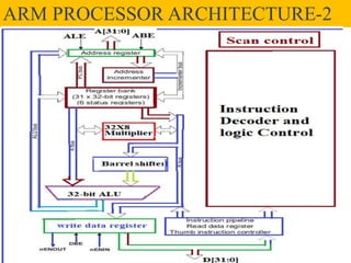
- 1. Block Diagram of ARM7ARM PROCESSOR ARCHITECTURE-2
- 2. ARM 7TDMI Processor • The ARM7TDMI is a member of the ARM family v4 of general-purpose 32-bit microprocessors. • The ARM family offers high performance for very low-power consumption . • ARM 7 is mainly based on Load/Store architecture. • Only load, store, and swap instructions can access data from memory using the registers. • To increase the efficiency of ARM7 a three stage pipeline architecture is used during the execution.
- 3. Load/Store Explanation • Let us consider an instruction : LDR R2,[R4]
- 4. contd • Let us now consider the instruction : STR R3,[R1]. • Here the data from the register is stored into memory location. • The operation is opposite to LDR where data from memory location is copied to Register. • Also in STR Rn,[Rx] , Rn is the source and [Rx] is the destination, which is also opposite as compared to LDR. • In LDR R2,[R4] instruction ,[R4] is the source and R2 is the destination.
- 5. Load/Store Explanation • Let us now consider the instruction : STR R3,[R1]
- 6. ARM 7TDMI Processor • The ARM7TDMI is a member of the ARM family v4 of general-purpose 32-bit microprocessors. • The ARM family offers high performance for very low-power consumption . • ARM 7 is mainly based on Load/Store architecture. • Only load, store, and swap instructions can access data from memory using the registers. • To increase the efficiency of ARM7 a three stage pipeline architecture is used during the execution.
- 7. Two Architectures • There are two popular computer architectures are in use.The first one was Von Neumann model after a famous Hungerian –American mathematician called John Luis von Neumann and the other model is Harvard Architecture. • The earlier computers were based on Von Neumann architecture (which is also popularly known as Princeton Architecture).This architecture uses same bus to carry both address and data from the memory. • As a single bus was used to perform both address and data operations naturally there was some delay..
- 8. Explanation • In the Neumann model a single memory is used both for Data and address.In first cycle ,the address is fetched and second cycle the data is fetched. So it’s a 2 cycle operation. • Harvard model there are separate address nd Data memories. So in a single cycle,both address and Data are fetched.24-07-2020 yayavaram@yahoo.com 8
- 9. contd • Harvard architectures , uses separate address and data buses to fetch the address and data from memories. • As,the ARM7 was designed based on Von Neumann architecture, to overcome the latency during the fetching operations, it was associated with piple line concept. • This pipeline concept provides parallel execution of instuctions. • In a single clock cycle two or operations are performed concurrently. This process enhances the efficiency.
- 10. Three Stage Pipeline • The three stage pipelined architecture of the ARM7 processor is shown below. • Here in the first stage fetch operation takes place and in the second stage decode operations and in the third stage operations related to execution takes place.
- 11. contd • In addition to 3-stage pipe line concept ARM also uses the Advanced Microcontroller Bus Architecture (AMBA bus architecture). • This AMBA include two system buses: the AMBA High-Speed Bus (AHB) or the Advanced System Bus (ASB), and the Advanced Peripheral Bus (APB). • While the ARM 7 is based on Neumann architecture , ARM 9 is based on Harvard model with 5 stage pipe line architecture.
- 12. Block Diagram of ARM7
- 13. Register Organization • ARM has a total of 37 registers. In which - 31 are general-purpose registers of 32-bits each, and six status registers . • But all these registers are not seen at once. The processor state and operating mode decide which registers are available to the programmer. • At any time, among the 31 general purpose registers only 16 registers are available to the user. • The remaining 15 registers are used to speed up exception processing. • Also there are two program status registers: CPSR and SPSR (Current Program Status Register & Saved Program Status Register respectively).
- 14. contd • In ARM state the registers r0 to r13 are orthogonal it means an instruction that is applied r0 can be equally applied to any other register. • The ARM processor has three registers assigned to a particular task or special function. They are r13, r14, and r15.
- 15. contd • The general purpose register usage is given below. Ex : MOV r5, r2 ADD r1, r2 LDR r0, [r1] STR R5,[R0]
- 16. contd • Register r13 is traditionally used as the stack pointer (sp) and stores the top of the stack in the current processor mode. • The Stack Pointer can be used as a general-purpose register in ARM state only. In Thumb, SP is strictly defined as the stack pointer. • R14 is used as the subroutine link register to store a copy of R15 when a Branch and Link (BL) instruction is executed. • In User mode, lr (or R14) is used as a link register and lr is used as a general-purpose register if the return address is stored on the stack.
- 17. contd • R15 is used as a Program counter which stores the address of the next instruction in the pipeline. • Also, the branch instructions load the destination address into PC. • At all other times these registers may be treated as a general-purpose registers.