

Recommended
More Related Content
What's hot
What's hot (15)
Viewers also liked
Viewers also liked (15)
Similar to Dold earth leakage indicator
Similar to Dold earth leakage indicator (20)
Recently uploaded
Recently uploaded (20)
Dold earth leakage indicator
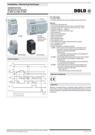
- 1. 1 01.04.15 en / 529 Installation / Monitoring Technique VARIMETER RCM Residual Current Monitor IL 5882, SL 5882, IR 5882 Your advantages • Compact design • As option with external or internal residual current transformer Features • According to IEC/EN 62 020 • for AC and pulsating DC currants Type A to IEC/TR 60755 • 9 tripping values from 10 mA to 10 A or from 10 mA ... 30 A • Frequency range 20 ... 2000 Hz • Selection of manual or automatic reset • With prewarning • With test and reset button • Broken wire detection • Short reaction time • With adjustable delay tv • De-energized on trip • LED indication for auxiliary supply and state of contact • 2 x 1 changeover contact • With sealable cover • Devices available in 3 enclosure versions: IL 5882: 63 mm deep with terminals near to the bottom to be mounted in consumer units or industrial distribution systems according to DIN 43 880 - width 35 mm - for connection of external residual current transformer, e. g. DOLD ND 5016, ND5019 SL 5882: 100 mm deep with terminals near to the top to be mounted in cabinets with mounting plate and cable ducts - width 35 mm - for connection of external residual current transformer, e. g. DOLD ND 5016, ND5019 IR 5882: 63 mm deep with terminals near to the bottom to be mounted in consumer units or industrial distribution systems according to DIN 43 88 - width 105 mm - with internal residual current transformer 0239971 Approvals and Markings Application Detection of insulation faults in grounded voltage systems. The residual current relay is used to maintain electrical plants before faults occur. De- crease in insulation can be detected and indicated early without interruption of operation. Function Diagram M8368_a A1/A2 t Alarm Prewarning i Alarm Prewarning 11-12 21-22 Test Reset manual reset with link X1/X2 with manual reset 11-14 21-24 11-14 tv tv tv manual reset manual reset tv ND 5016/024 ND 5019/035 IR 5882 with internal residual current transformer IL 5882 All technical data in this list relate to the state at the moment of edition. We reserve the right for technical improvements and changes at any time.
- 2. 2 01.04.15 en / 529 Setting LED "ON" LED "Prewarning" LED "Alarm" setting of alarm value time delay for alarm and prewarning Reset button Test button M8369_b Indication green LED "ON": on, when supply connected red LEDs "VW", "AL": on, when insulation failure (prewarning and alarm) Note If time is set to 0 and a pulsating fault current is flowing (e.g. 1-way rec- tified) the output relay may flicker because of the short reaction time. By increasing the time delay this effect can be avoided. Circuit Diagrams M8349_a X1 14 A1 24 i 12 22 X2 11 A2 21 k A1 X1 i k A2 X2 11 21 12 22 14 24 AL VW A1 X1 PE A2 X2 4 11 21 12 22 14 24 L1/L2/L3/N M111342414 2212 2111 A2A1X1 X2 AL VW IR 5882 IL /SL 5882 Connection terminals Terminal designation Signal designation A1, A2 Auxiliary voltage i, k (only at IL/SL 5882) Conn.f.external current transformer ND5016, ND5019 ; terminals i, k X1, X2 control input X1/X2 bridged: with manual reset of alarm X1/X2 not bridged: without manual reset of alarm (Hysteresis function) 11, 12, 14 1. C/O contact (Alarm) 21, 22, 24 1. C/O contact (Pre-warning) Function The function of the IL/SL 5882 and IR 5882 can be compared to a fault current circuit braker unit. It detects and indicates residual currents, but does not disconnect. The measurement is done by an external residual current transformer e. g. ND 5016 which is connected via terminals i and k to the IL/SL 5882. At the device IR 5882 the residual current transformer is integrated. All conductors of the voltage system to be monitored are run through the CT except the ground wire. In a fault free voltage system the sum of all current is 0 and the CT induces no secondary voltage. If due to an insulation fault a fault current flows to ground, the current difference in the CT creates a measuring current, which is detected and measured by the IL/SL 5882 or IR5882.Abrokenwireinthesensingcircuitwoulddisablethemeasurement, therefore a special circuit detects broken wire and forces the unit to trip. The unit has 2 x 1 changeover contacts. Contact 11-12-14 for alarm (AL) and 21-22-24 for prewarning (VW). Prewarning is detected at 70 % of the selected alarm value. With external bridge X1-X2 the alarm is stored and has to be reset by pressing the reset button or by disconnecting the auxi- liary supply. Without bridge X1-X2 the unit works with auto-reset and the fault is not stored. With the button "Test" a fault can be simulated (Alarm). Each contact is delayed with an adjustable time delay tv (same delay time for alarm and pre-warning). To avoid unauthorised adjustment of the potentiometers the unit has a transparent cover that could be seald with laquer. Two holes above the push buttons allow activation of test and reset.
- 3. 3 01.04.15 en / 529 Terminal designation: EN 50 005 Wire connection: 2 x 2.5 mm2 solid or 2 x 1.5 mm2 stranded wire with sleeve DIN 46 228-1/-2/-3/-4 Wire fixing: Flat terminals with self-lifting clamping piece IEC/EN 60 999-1 Mounting: DIN rail IEC/EN 60 715 Weight IL 5882: approx. 125 g SL 5882: approx. 150 g IR 5882: approx. 300 g Dimensions Width x height x depth: IL 5882: 35 x 90 x 63 mm SL 5882: 35 x 90 x 100 mm IR 5882: 105 x 90 x 63 mm (inner diameter current transformer: 21.5 mm or 28 mm) Technical Data Technical Data Input Auxiliary voltage UH : AC/DC 12 V, AC/DC 24 ... 230 V Voltage range: AC: 0.8 ... 1.1 UN DC: 0.9 ... 1.25 UN Nominal frequency UH : 50 ... 400 Hz Nominal consumption AC 230 V: 4 VA AC 24 V: 1.6 VA DC 24 V: 1 W Measuring value adjustable via rotational switch: AC 0.01; 0.03 A; 0.1 A; 0.3 A; 0.6 A 1 A; 2 A; 5 A; 10 A or AC 0,01 A, 0,03 A; 0,1 A; 0,3 A; 0,6 A 1 A; 2 A; 7 A; 30 A Frequency range: 20 Hz ... 2 kHz at failure current < 50 Hz and the function "auto reset", a time delay must be adjusted, so that the relay does not buzz before switching Hysteresis: approx. 4% of trip value, fixed Accuracy: ≤ ± 15 % Repeat accuracy: ≤ ± 1 % Temperature drift: ≤ ± 0.05 % / K Reaction time: 10 ... 30 ms Response delay tv : 0 ... 5 s adjustable (logarithmic scale in order to allow also short time delay to be adjusted without problems) Output Contacts: IL / SL / IR 5882.38: 1 changeover contact for Prewarning, 1 changeover contact for Alarm Thermal current Ith : 5 A Switching capacity to AC 15: NO contact: 3 A / AC 230 V EN 60 947-5-1 NC contact: 1 A / AC 230 V EN 60 947-5-1 Electrical life to AC 15 at 1 A, AC 230 V: 3 x 10⁵ switching cycles EN 60 947-5-1 Short circuit strength max. fuse rating: 4 A gL EN 60 947-5-1 Mechanical life: ≥ 108 switching cycles General Data Operating mode: Continuous Temperature range: - 20 ... + 60°C Clearance and creepage distances rated impulse voltage / pollution degree supply / contacts: 4 kV / 2 IEC 60 664-1 supply / Measuring Circuit: corresponding to CT EMC Surge voltages: class 3 (5 kV / 0.5 J) DIN VDE 0435-303 HF-interference: class 3 (2.5 kV) DIN VDE 0435-303 Electrostatic discharge: 8 kV (air) IEC/EN 61 000-4-2 HF irradiation IEC/EN 61 000-4-3, EN 50 121-3-2 80 MHz ... 1 GHz: 20 V / m 1 GHz ... 2,7 GHz: 10 V / m Fast transients: 4 kV (class 3) IEC/EN 61 000-4-4 Surge voltages: 2 kV (class 3) IEC/EN 61 000-4-5 Interference suppression: Limit value class B EN 55 011 Degree of protection: Housing: IP 40 IEC/EN 60 529 Terminals: IP 20 IEC/EN 60 529 Housing: Thermoplastic with V0-behaviour according UL subject 94 Vibration resistance: Amplitude 0.35 mm frequency 10 ... 55 Hz IEC/EN 60 068-2-6 Climate resistance: 20 / 060 / 03 IEC/EN 60 068-1 Standard Types IL 5882.38 AC/DC 24 ... 230 V 50 / 60 Hz 10 A 5 s Article number: 0055138 • De-energized on trip • Auxiliary voltage UH : AC/DC 24 ... 230 V • Measuring range: 10 A • Response delay tv : 5 s • Width: 35 mm SL 5882.38 AC/DC 24 ... 230 V 50 / 60 Hz 10 A 5 s Article number: 0055515 • De-energized on trip • Auxiliary voltage UH : AC/DC 24 ... 230 V • Measuring range: 10 A • Response delay tv : 5 s • Width: 35 mm IR 5882.38 AC/DC 24 ... 230 V 50 / 60 Hz 10 A 5 s Article number: 0066743 • Internal residual current transformer (Ø 28 mm) • De-energized on trip • Auxiliary voltage UH : AC/DC 24 ... 230 V • Measuring range: 10 A • Response delay tv : 5 s • Width: 105 mm ND 5016/024 Article number: 0066009 • Residual current transformer for IL/SL 5882 • Diameter: 24 mm • DIN-rail mounting: waagrecht oder senkrecht • Screw mounting: M4 IL 5882.12/002: with 2 changeover contacts for alarm and no pre-warning Ordering example for variant IL 5882 .38 /_ _ _ AC/DC 24 ... 230 V 50/60 Hz 10 A 5 s Response delay Measuring range Frequency range Auxiliary voltage Variant, if required Contacts Type Variant
- 4. 4 01.04.15 en / 529 Accessories Technical Data Ambient temperature ND 5016: - 20 ... + 60°C / 253 K ... 333 K ND 5019: - 10 ... + 50°C / 263 K ... 323 K Inflammability class: V0 according to UL94 Nominal insulation voltage acc. to IEC 60 664-1: AC 630 V Rated impulse voltage / pollution degree: 6 kV/3 Voltage test acc. to DIN VDE 0435-303 / IEC/EN 60 255: AC 3 kV Transformation ratio: 500 /1 Length of connection wires Type of wire: Single wire: up to 1 m Single wire Twisted pair: up to 10 m Screened wire; screen on terminal k: up to 25 m Wire cross section ND 5016: 0,2 ... 1,5 mm2 ND 5019: 0,75 mm2 Stripping length: 8 mm Wire fixing ND 5016: Terminals with spring connection and direct (Push in) technology ND 5019: Box terminals Screw connection: ND 5016/024: M4 ND 5019/035, ND 5019/070, ND 5019/105: M 5 DIN rail mounting: ND 5016: integrated clips for vertical and horizontal mounting ND 5019: using mounting adapter ET 5018 for DIN rail mounting or screw mounting Residual Current Transformer ND 5019 for Screw connection The residual current transformers ND 5019/035, ND 5019/070, ND 5019/105 can also be mounted on DIN-rail. To do this the metal screw fixings have to be removed and have to be replaced by 2 mounting clips (ET5018: art. no. 0058754; set with 2 pcs) Dimensions in mm ND 5019/035 ND 5019/070 ND 5019/105 Art-No. 0055116 0055117 0055118 øD 35 70 105 L 100 130 170 B 33 33 33 H 79 110 146 C 26 32 38 D 48.5 66 94 E 46 46 46 F 61 61 61 k 6.5 6.5 6.5 m 16 16 16 Weight ND 5019/035 ND 5019/070 ND 5019/105 kg 0.15 0.24 0.5 ND 5016/024 Art-No. 0066009 kg 0.08 Residual Current Transformer ND 5016 M10979_a 24 41,3 45,5 4,2 24 5 75 82 4 25 D B m k E F L H M7486 D C D B L H M9777_b G
- 5. 5 01.04.15 en / 529 Installation of Wires PE PE PEN NL1 L+ L1 L1 L2 L- L2 L2 L3 L3 L3 M8362_a To Avoid Interference with High Starting Currents M8363 Connection Example Attention: As the auxiliary supply has no galvanic separation, the se- condary circuit of the CT must not be connected to ground. A ground connection will lead to a damage of the unit! Disassembling Residual Current Transformator ND 5016 M11123 PE L1 L2 L3 N i k X1 X2 11 12 14 21 22 24 A1 A2 IL5882 i k X1-X2 open : automatic reset X1-X2 closed : manual reset * only IL5882, SL5882 Alarm signalling contacts Prewarning 11 21 M8370_c 12 14 2422 monitored voltage system *
- 6. 6 01.04.15 en / 529 E. DOLD & SÖHNE KG • D-78114 Furtwangen e-mail: dold-relays@dold.com • internet: http://www.dold.com • POBox1251•Telephone(+49)7723 / 654-0 •Telefax (+49) 77 23 / 654-356