5-Axis high-speed machining center for precision dies & molds
•
0 likes•66 views

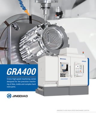
The document describes a GRA400 5-axis high-speed machining center capable of precision machining of dies, molds, and complex hardware parts. It has fully closed-loop control for 5-axis machining and can achieve machining effects of 0.1 μm feed, 1 μm cutting, and nanoscale roughness stability. It also has a strong load capacity direct drive double axis rotary table with high machining accuracy.

Recommended
More Related Content
What's hot
What's hot (20)
Similar to 5-Axis high-speed machining center for precision dies & molds
Similar to 5-Axis high-speed machining center for precision dies & molds (20)
Recently uploaded
Recently uploaded (20)
5-Axis high-speed machining center for precision dies & molds
- 1. GRA400 5-Axis high-speed machining center designed for the precision machin- ing of dies, molds and complex hard- ware parts. JINGDIAO 5-AXIS HIGH-SPEED MACHINING CENTER
- 2. With fully closed-loop control technology, the GRA400 is suitable for 5-axis machining of precision mold, precision parts and complex hardware parts. GRA400 Highlights The machining effect of "0.1 μm feed, 1 μm cutting, nanoscale roughness" can be achieved stably. 01 The machines are capable of milling, grinding, drill- ing, boring, tap-ping, and other composite process- ing, and side milling . 02 The direct drive double axis rotary table has a strong load capacity with high machining accuracy. 03 Using the cooling technology of rotary table, bearing and screw nut and the fully enclosed shield improve the thermal stability of machine tool effectively. 04 01 02 03 04 Learn More About GRA400 01
- 3. Machine Structure Higher Motion Accuracy Full closed loop control, motion axes equipped with linear glass scales. Good Thermal Stability All round cooling design, using rotary table cooling, bearing cooling, screw cooling technology, and equipped with fully enclosed machine covers. Better Machine Rigidity Inverted “L” structure. More Stable Geometric Accuracy Classical fixed beam gantry structure. Max. load (kg/lb): 150/330.7 Max. Workpiece Dimension Z-axisZ-axis X-axisX-axis C-axisC-axis A-axisA-axis Y-axis Y-axis Travel (X/Y/Z) mm/ (in) 450/680/400 (17.7/26.8/15.7) A/C Rotation Angle (deg) -120~90/360 φ500 (φ19.7) 410(16.1) 319(12.6) Ergonomics The Operator Loads the Workpiece Through the Front Door of the Machine, and the Chip Conveyor is Completed by the In-Machine Spiral Chip Conveyor Rod. In order to facilitate the operation of the machine, the structural de- sign of each operation part conforms to the ergonomics. The worktable is close to the operator, which makes it easy to load and unload the workpiece. Pneumatic components and lubricating components are all in- stalled on the right side of the machine, which is convenient for inspection and maintenance. The tool magazine door has a large opening degree, which is convenient for the loading and unloading of tools. Unit:mm (in) 1750(68.9) 1080 (42.5) 550 (21.7) 02 Unit: mm (in)
- 4. JD150S-20-HA50/A Performance Taper Bore Radial Runout ≤1.5 μm (5.9×10⁻⁵ in) Rotor End Face Axial Runout ≤1 μm (3.9×10⁻⁵ in) Vibration at Maximum Speed ≤0.6 mm/s (1.44 ipm) Clamping Diameter (mm/in): Φ150/Φ5.9 (0, -0.009) mm Output Power (S6-60%): 18 KW Output Torque (S6-60%): 21.5 Nm Speed: 20,000 rpm Tool Holder: HSK-A50 Weight (kg/lb): 46.5/102.5 Basic Specification Output Performance Key Components 6-φ9 (φ0.4) Through-Hole Uniform Distribution 6-φ9 (φ0.4) Through-Hole Uniform Distribution φ15 (φ0.6) 12 Uniform Distribution φ15 (φ0.6) 12 Uniform Distribution R86 (3.4) R84 (3.3) 15° 15° PEAK S6.60% S1.100% 0 5 10 15 20 25 30 35 0.5 0.8 1 1.5 TorqueT(N.m) Speed n/×104 (rpm) 2 JINGDIAO High-Speed Precision Spindle JINGDIAO's high speed spindles are the machine's main power source which produce precision machining results. Our in-house built spin- dles have low vibration, and high thermal stability resulting in a small Coefficient of thermal expansion and stable cutting in conditions. Machining Samples Composite Machining Test Piece Realize milling, drilling, tapping, reaming, boring and other composite processing with one clamping. 200×150×150 /7.9×5.9×5.9 Al 6061 Size (mm/in): Material: Highlights: Mold Insert of Auto Engine Cylinder 183×184×191 /7.2×7.2×7.5 Throttle Die Casting Size (mm/in): H13 (HRC52)Material: The virtual processing technology of JINGDIAO CAM software completes the optimization of the tools’ clamping length and machining angle; Cornering of the side wall with R0.75 mm ball end mill. Highlights: The coaxiality of the hole is less than 0.01 mm, and the roughness of the reaming hole is less than 0.2 μm; JINGDIAO on-machine measurement technol- ogy achieves continuous and stable mass pro- duction, and the yield of the part is increased from 70% to 98%. 135×115×75 /5.3×4.5×3.0 ADC12 (HB90) 12% Silicon Size (mm/in): Material: Highlights: 03 JD150S-20-HA50/A Dimension Unit:mm (in) φ192(φ7.6) φ153(φ6.0) φ110(φ4.3) φ150(φ5.9) φ149.9(φ5.9) 45.5 (1.8) 597 (23.5) 142 (5.6)100 (3.9) 4.5 (0.2) 2 (0.1) 22 (0.9) Clamping Position PEAK S6-60% S1-100% 0.5 0 5 10 15 20 25 30 35 0.8 1 1.5 Speed n/×104 (rpm) PowerP(KW) 2
- 5. JD150SC-20-HA50 (Coolant Through Spindle) Optional Basic Specification Clamping Diameter (mm/in): Φ150/Φ5.9 (0, -0.009) mm Output Power (S6-60%): 18 KW Output Torque (S6-60%): 21.5 Nm Speed: 20,000 rpm Tool Holder: HSK-A50 Weight (kg/lb): 46.5/102.5 Speed: 20,000 rpm Tool Holder: HSK-A50 04 JD130S-24-BT30 Speed: 24,000 rpm Tool Holder: BT30 JD130EF-32-HE32 Speed: 32,000 rpm Tool Holder: HSK-E32 JD130SC-24-HA40 Speed: 24,000 rpm Tool Holder: HSK-A40 JD130SCG-24-HA40 Speed: 24,000 rpm Tool Holder: HSK-A40 JD150SCG-20-HA50 Speed: 20,000 rpm Tool Holder: HSK-A50 When machining with coolant through spin- dle, the cutting fluid or cutting oil is ejected to the tool tip through the hole of the internal cooling tool. This can improve the cooling and lubricating effects on the tool and work- piece. Coolant thrugh the spindle is hepful in deep hole drilling since the chips are quickly discharged through the spiral groove of the drill. This greatly improves the machining effi- ciency and tool durability. Cutting Test Results (Spindle Type JD150S-20-HA50/A 20,000rpm) Item Material Teeth Number Tool Size mm/in Cutting Width (mm/in) Spindle Speed rpm Cutting Feed Rate mm/min (in/min) Cutting Capacity cm³/mmCutting Depth (mm/in) Face Mill Aluminum 7 φ80/φ3.15 70/2.8 6000 3200 (126.0) 448 2/0.08 Steel 4 φ50/φ2.0 45/1.8 1000 1000 (39.3) 36 0.8/0.03 End Mill Aluminum 4 φ16/φ0.6 3.2/0.1 10000 3200 (126.0) 327.68 32/1.3 Steel 4 φ16/φ0.6 1/0.04 3600 2400 (94.5) 76.8 32/1.3 Drill Aluminum 2 φ24/φ0.9 / 1000 200 (7.9) / Steel 2 φ24/φ0.9 / 1000 100 (3.9) / Tap Aluminum 2 M20×1.5 / 700 1050 (41.3) / Steel 2 M14×1.5 / 400 600 (23.6) / D W D W Different machining conditions have different machining data, which is only for reference.
- 6. The programming resolution and control resolution are 0.1 μm (3.9×10⁻⁶ in). Basic Characteristics Supports linear, plane arc, space arc, spiral line, spline and involute interpolation methods. Support pitch compensation and reverse clearance compensation. Support RTCP multi-axis motion control. JD50 CNC System The JD50 CNC system is developed independently by JINGDIAO. The control is highly efficient, reliable and very precise. Additionally, it has rich programming functions, convenient operation, flexible peripheral control, and can meet the processing Re- quirements of high machining accuracy and fine surface finishing. 0.1μm Feed, 1μm Cutting Fixed Point Cutting RTCP Not RTCP Program RTCP Program G91G28Z0 G90 G0X0.7883Y2.4874A-90.C-77.1431 M590 L1 G43H1 Z35.0874 Z30.6074 N102G1Z30.1074F189. G91G28Z0 G90 G68.2X29.3331Y6.6949Z-6.I-77.143J-90.K0. G53.1 G0X0.7883Y-3.5126 M590 L1 G43H1 Z5. Z0.52 N102G1Z0.02F189. IntuitiveNot intuitive Five-Axis Programming Features Tool center point control function. Inclined plane machining function. Cylinder interpolation function. Polar coordinate interpolation function. 05
- 7. Remote Monitoring of Machines System Advantages Various programming methods and flexible technical process design. Abundant types of interfaces and buses, with strong peripheral expansion capabilities. Unique external extended function instructions (G100), which can realize instruction-level peripheral control, human-computer interaction, and complex data operations. Logo Inspection G100 Instruction Data Management Advanced Features Includes on-machine contact and non-contact measurement functions, which results in high-precision 2D and 3D measurements. Built-In CAM technology and intelligent modification technology supports the on-machine tool-path deformation compensation machining. Incorporates multiple communication protocols and remote monitoring. Non-Contact Measurement Contact Measurement 06 Surface Deformation Compensation Inspection Position 1 Inspection Position 2
- 8. Tool Magazine To meet your production needs, we have a vari- ety of tool magazines to choose from. Type Chain Type Tool Magazine with Manipulator Capacity 53 Tool Holder HSK-A50 Allowable Maximum Tool Length (mm/in) (From End of Spindle) 260/10.2 Maximum Diameter of Contiguous Tools (Full) (mm/in) 50/2.0 Maximum Diameter of Contiguous Tools (Vacant) (mm/in) 90/4.7 Max. Load of Each Position (kg/lb) 3.5/7.7 Max. Load of Tool Magazine (kg/lb) 120/264.6 Type Chain Type Tool Magazine with Manipulator Capacity 63 Tool Holder HSK-A50 Allowable Maximum Tool Length (mm/in) (From End of Spindle) 260/10.2 Maximum Diameter of Contiguous Tools (Full) (mm/in) 50/2.0 Maximum Diameter of Contiguous Tools (Vacant) (mm/in) 105/4.1 Max. Load of Each Position (kg/lb) 3.5/7.7 Max. Load of Tool Magazine (kg/lb) 130/286.6 Type Chain Type Tool Magazine with Manipulator Capacity 36 Tool Holder HSK-A50 BT30 Allowable Maximum Tool Length (mm/in) (From End of Spindle) 260/10.2 200/7.9 Maximum Diameter of Contiguous Tools (Full) (mm/in) 50/2.0 50/2.0 Maximum Diameter of Contiguous Tools (Vacant) (mm/in) 90/3.5 90/3.5 Max. Load of Each Position (kg/lb) 3.5/7.7 3/6.6 Max. Load of Tool Magazine (kg/lb) 85/187.4 85/187.4 07
- 9. Specification Item Tilt Axis (A) Rotation Axis (C) Position Accuracy (″) 8 8 Repeatability (″) 5 5 Rapid Feed Rate (rpm) 60 100 Cutting Speed (rpm) 60 100 Cooling Mode Circulating Water Cooling Circulating Water Cooling Positioning Locking Mode Hydraulic Locking Hydraulic Locking Positioning Locking Air Pressure (MPa) 5 5 Safety Brake √ —— Cradle Type Double Direct Drive Rotary Table Assures high-precision multi-axis machining. Dimension 538(21.18) 1371 (53.98) φ400 (15.75) 60(2.36) 434.5 (17.1) Features Direct drive motor, with emergency braking function. Bridge deck tailstock structure, high precision and stable operation. Circulating water cooling technology reduces the thermal deformation. Five-Axis simultaneous processing, multi surface positioning processing. The hollow design in the shaft makes the pipeline layout more convenient. 08 Unit: mm (in)
- 10. Accessories MHS150 Material Handling System MHS150 material handling system is mainly composed of handling manipulator, storage module and control system. It is equipped with tridimensional fixed plate exchange system, which can realize the automatic handling of workpiece under the condition of no human intervention. Configuration 01 Processing System 02 Feeding System 03 Clamping System 04 Software System 1846 (72.7) 2055 (80.1) 253(10.0) 1060(41.7) 1665(65.6) 2495(98.2) 2733(107.6) 1821(71.7) 1933 (76.1) 2315 (91.1) 2819 (111.0) Workpiece Dimension (mm/in) Specification MHS150 Specifications Feeding System MHS150-SR6A Load (kg/lb) 150 (330.7) Storage Capacity 6 Workpiece Dimension (mm/in) 400×330×260 (15.7×13.0×10.2) Machine Dimension (mm/in) 2055×2819×2733 (81.0×111.0×107.6) Weight (kg/lb) 6000 (13227.7) Unit: mm (in) 09 330 (13.0) 400 (15.7) 260(10.2) C50
- 11. Continuous Loading, Continuous Machining When equipped with MHS150 material handling system, the GRA400 can achieve continuous and stable unattended production. 01 03 04 02 Production Mode The exceptional features of JINDAIO operation management system makes it easier to collaborate with colleagues within in your man- ufacturing team. The personnel will perform Their respective duties, guarantee the continuous operation of the system, and improve the machines' actual utilization rate. Factory Supervisor Operator Technologist Dispatcher Workshop Supervisor Obtain Production Information in Time Maintain Synchronous Programming Production Scheduling Real Time Statistics of Machine State Preparation Network Transmission Flexible Adjustment Customized Service We can design and develop the structure accord- ing to your actual production needs. 3520(138.58) 2800(110.24) The Position of Chip Conveyor When It is Maintained Tool Magazine Door R665 Control Cabinet Door R468 3940(155.12) 4800(188.98) 2870(112.99) 2020 (79.53) 3020 (118.90) 3620 (142.52) 5670 (223.23) 6120 (240.94) Control Cabinet Door R700 Back Door R494 Unit: mm (in) 10 Debug Verification Requirement Analysis Maintenance Training Project Delivery Project Design
- 12. Scraper Style Chip Conveyor System The scraper style chip conveyor collects and filters out the collection of cutting chips from the machining fluid. Scraper Type Chip Conveyor Filtering Tank Chip Collector Features Improves maintenance by moving the the chips into disposal container. Cutting fluid service life is extended by using a multistage filtration unit. Equipped with a cleaning mechanism and drop recovery mechanism which is self cleaning resulting cutting fluid recovery. The oil mist collector reduces the rise of internal temperature caused by the oil mist accumulation. It eliminates the diffu- sion of oil mist, reduces the internal elec- trical fault of the machine tool, improves the stability of equipment operation, reduces air pollution, and protects the workshop environment. Oil Mist Collector GL370 Oil Mist Collector Specification Item Spec Voltage (V) AC380±10% Power (W) 370 Current (A) 0.95 Frequency (Hz) 50±2% Ambient Temperature (℃ / ℉ ) 5~40/41~104 Environmental Pressure Atmos Weight (kg/lb) 80/176.4 Max. Air Volume (m3 /in3 ) 450/2.7×107 Filtration Efficiency > 99% 11 Material Chip Form Chip Size Applicability Steel Long Short Powder Cast Iron Short Powder Aluminum/ Non-ferrous Metal Long Cumulus Short :Ideal :Suitable :Not Suitable Appropriate Chip Types Chip Conveyor Principle
- 13. SpecificationDimension 85 (3.3)135 (5.3) 270(10.6) Minimal Quantity Lubrication (MQL) MQL cooling is used in precision grinding and micro milling. Equipped with MQL, the temperature fluctuation in the machine can be controlled within 0.5 °C (32.9 °F). Minimal Quantity Lubrication (MQL) MQL cooling technology is used in precision grinding and micro milling. Equipped with MQL, the temperature fluctuation in the machine can be controlled within 0.5 °C (32.9 °F). Item Spec Pressure (MPa) 0.5~0.8 Working Pressure (MPa) 0.55 Air Volume (L/min) 0~220 Air Consumption per Nozzle (L/min) 100 Oil Consumption per Nozzlem (ml/h) 0~30 Nozzle Quantity 2 Weight (kg/lb) 1.5/3.3 Mounting Pitch (mm/in) 70/2.8 Type Name Size mm (in.) A B C L Thread BT30 BT30-ER11-85S 7.5 (0.30) 19 (0.75) 35 (1.38) 82 (3.23) M14×0.75 BT30-ER16-60S 10.5 (0.41) 30 (1.18) 50 (1.97) 67 (2.64) M22×1.5 BT30-ER16-100S 10.5 (0.41) 30 (1.18) 50 (1.97) 107 (4.21) M22×1.5 HSK-A HSK-A40-ER16-060HS 10.5 (0.41) 30 (1.18) 28.5 (1.12) 65 (2.56) M22×1.5 HSK-A50-ER11-080S 7 (0.28) 19 (0.75) 30 (1.18) 80 (3.15) M14×0.75 HSK-A50-ER16-070S 10.5 (0.41) 30 (1.18) 40 (1.57) 71 (2.95) M22×1.5 HSK-A50-ER16-110S 10.5 (0.41) 30 (1.18) 40 (1.57) 111 (4.37) M22×1.5 HSK-E HSK-E32-ER16-060HS 10.5 (0.41) 30 (1.18) 27.5 (1.08) 65 (2.56) M22×1.5 Tool Holders Tool holders require good clamping performance such as high clamping accuracy, low vibration and the ability minimize oil mist during high-speed machining. JINGDIAO tool holders have anticorrosive properties, minimize air resistance, and are designed good dynamic balance. Our tool holders are available in various styled including BT30, HSK. Technical ParameterDimension Comparison Chart 12 Unit: mm (in) A A B B C C L L
- 14. Real Time Display of CNC System Distinctive Technologies On-Machine Measurement and Intelligent Modification Technology JINGDIAO's innovative on-machine measurement and intelligent modification technology (omim) is a ideal solution that integrates CAM programming technology, numerical control processing and precision inspection technology. Its intelligent application can effec- tively shorten the production cycle of the workpiece, streamline the processing flow, and improve quality and efficiency for production and machining. 13 With this feature, the remaining stock at each machining step can be measured in real time, and the inspection results will be dis- played on the machine's control. The operator can analyze the results in order to ensure that an even amount of material is removed at every machining step. This results in reduced tool wear, constant chip load, improved machining accuracy and improved surface finishes. Machining Step Remaining Stock Inspection Inspect the Remaining Stock on the Machine Achieve Stable Precision Machining The Function of JINGDIAO OMIM is Mainly Reflected in Three Aspects This feature automatically corrects the workpiece deviation through inspecting the offset of workpiece on machine and adjusting the program in control system. This reduces workpiece setup time, improves machining quality and increases production. Intelligent Workpiece Alignment Before Modification: 7 μm ID-6 ID-7 Remain Remain0.10883 0.10347 ID-5 ID-8 Remain Remain0.10985 0.10245 ID-4 ID-9 Remain Remain0.10868 0.10325 ID-2 ID-11 Remain Remain0.10860 0.10302 ID-3 ID-10 Remain Remain0.10828 0.10229 ID-1 Remain 0.10789 After Modification: 4 μm ID-7 Remain 0.10219 ID-8 Remain 0.10136 ID-9 Remain 0.10187 ID-11 Remain 0.10174 ID-10 Remain 0.10101 ID-6 Remain 0.10234 ID-5 Remain 0.10287 ID-4 Remain 0.10169 ID-2 Remain 0.10161 ID-3 Remain 0.10130 ID-1 Remain 0.10289 03-Workpiece Position Compensation Workpiece Clamping Error Ideal Clamping Actual Clamping Plane Line Point One Plane and Two Circle Body of Revolution Three Plane Plane and Slot Self Define 01-Support Multiple Workpiece Position Compensation Methods 02-Obtain Actual Position on the Machine Unilateral allowance is 15μm Precision Fitting 04-Verification of Position Compensation Accuracy
- 15. Theoretical Path Adjusted Path Machining and inspection are achieved on one machine, forming a new model of "integration of machining and inspection". The digitalization of CNC machining experience enables a entry-level operator to complete precision machining. The actual processing time proportion of CNC machines has increased from 25% -45% to 45% -70%. A New Model of Numerical Control Processing The CAM function embedded in the CNC system can compensate the inaccurate machining path, which caused by workpiece deformation, clamp- ing deformation and clamping deviation, achieve five-axis adaptive machining. 5-Axis Path On-Machine Compensation Surface Date Measurement Adjust Processing Path Egg Processing Egg Demonstration Tool Type* Ball-End Tool Nose Tool Taper Ball-End Tool Tool Inspection System During the 5-axis machining process, JINGDIAO tool inspection system can inspect the errors of different positions of the tool contour of the bull nose tool, ball-end tool and other tools for precision machining and compensate intelligently. This can effectively reduce the unqualified workpiece accuracy caused by the tool inaccuracy. 14 Before Using Integration of Machining and Inspection After Using Integration of Machining and Inspection Realization 3D Tool Contour Compensation Function 05 25 45 60 90 *Measure per 5° Inspect Tool Contour on the Machine Compensate Tool Contour Deviation G41 P2 D3 X-73.5376 Z-1.8930 NX6711.5031 NY-1.5915NZ7413.2128 JIGNDIAO CAM Software Standard Laser Tool Set JIGNDIAO CNC System Workpiece
- 16. Five-axis milling is a complex machining process. During the machining there is the risk of collisions between tools, tool holders and the workpiece. JINGDIAO uses its SurfMill software to establish the connection between production materials, CAM programming and actual processing in a virtual environment. The user can build the same digital scene in the software, simulate the machining process, analyze and adjust the process, and eliminate the machining risk in the software programming stage. Ensuring the Safety of 5-Axis Machining With JINGDIAO's software, the actual production materials and process parameters are digitized to ensure the correct information is selected by the process personnel, material preparation personnel and the operator. This creates a seamless integration process de- velopment, material preparation and machine operation, and improves the accuracy and fluency of the machining Process. 15 JINGDIAO Virtual Manufacturing Technology Machine Bank Tool Bank Tool Holder Bank Fixture Bank Tool Holder Tool Machine Fixture
- 17. Application Scenarios of JINGDIAO Virtual Manufacturing Technology Technical Points Mirror the Actual Machining Environment to Ensure the Accuracy of Interference Risk Inspection Informatization of Production Materials to Avoid Risks Caused by Wrong Selection of Materials The Macro Program Fool-Proof to Avoid Risk Caused by Mis-Operation by Personnel Risk Type Cause Of Risk Solutions Z-Axis and Workpiece Tool Holder and Workpiece Ignore Z-Axis Complete Machine Model Spindle and Workpiece Informatization of Production Materials Tool Holder Selection No Informatization of Production Material Calculation Path Collision Tool Holder Selection Wrong Selection Map Tool Holder Magazine No Collision Path Calculation Tool Clamping Length Error Tool Setup Foolproof Logically Judge Whether the Tool Clamping Length is Within the Safe Value Range Execution Condition Implementation Results Within Safe Range Exceed Safety Value With this software, the program processing, measurement, preparation and logical judgment are combined into one program. The op- erator only needs to press the start button to begin the processing of the part which reduces machine setup time. Easy Start Processing Easy Start Processing Program Measurement Program Preparation Program Warm up Machine Tool Inspection Warm up Machine Path Travel Fool-Proof ... ... M98 P5001(Warm up Machine) M98 P5002(Tool Inspection) M98 P5003(Calibration) M98 P5004(Path Travel Fool-Proof) M98 P5005(Processing Program) ... Logical Judgment If[[#1 Eq 0] || [#2 Eq 0]…[#18 Eq 0]]Goto 1 (Cycle Condition: Unqualified Remaining Stock at Any Point) Goto999 N1 (Execute the Pop-up Program) G65 P495 A18 (Real-Time Actual Remaining Stock Displayed on the Pop-up) N999 M99 16 1 2 3
- 18. Dimension Layout Front View Left View 3080 (121.3.0) 2530 (99.6) 2840(111.8) 3150 (124.0) R468 (R18.4) R567 (R22.3) R570 (R22.4) R345(R13.6) 2540(100.0) R417 (R16.4) 17 Technical Specification Unit: mm (in) Unit: mm (in)
- 19. Stroke Diagram Items Standard Value Position Accuracy (X/Y/Z) mm/ (in) 0.002/0.002/0.002 (0.00008/0.00008/0.00008) Position Accuracy (A/C) sec 8/8 Repeatability (X/Y/Z) mm/ (in) 0.0018/ 0.0018/ 0.0018 (0.00007/0.00007/0.00007) Repeatability (A/C) sec 5/5 Travel (X/Y/Z) (mm/in) 450/680/400 (21.7/26.8/15.7) A/C Rotation Angle deg -120~90/360 Table Diameter (mm/in) φ400/φ15.7 Max. Load (kg/lb) 150/330.8 Max. Spindle Speed (rpm) 32,000 (HSK-E32) 24,000 (BT30) 20,000 (HSK-A50) Tool Magazine/Capacity 63 (Chain-Type Tool Magazine) Rapid Speed (X/Y/Z) m/min (in/min) 15 (590.6) Rapid Rotation Speed (A/C) rpm 60/100 Max. Cutting Feed Speed (X/Y/Z) m/min (in/min) 10 (393.7) Max. Cutting Feed Speed (A/C) rpm 60/100 Drive System AC Servo Voltage 3-Phase, 480V/60Hz Air Pressure (MPa) ≥0.52 Machine Weight (kg/lb) 10700/23593.5 Standard Features and Options Items Configuration Control System JD50 CNC System CAM Software JDSoft SurfMill 8.0 Spindle JD130EF-32-HE32 JD130S-24-BT30 (BT30) JD130SC-24-HA40 (HSK-A40, Coolant through) JD130SCG-24-HA40 (HSK-A40, Coolant through, Grinding) JD150S-20-HA50/A (HSK-A50) JD150SC-20-HA50 (HSK-A50, Coolant through) JD150SCG-20-HA50 (HSK-A50, Coolant Through, Grinding) Items Configuration Tool Magazine Chain Type Tool Magazine with Manipulator (63 Tools) (HSK-A50) Chain Type Tool Magazine with Manipulator (53 Tools) (HSK-A50) Chain Type Tool Magazine with Manipulator (36 Tools) Cooling System Coolant Device (Half Ring Nozzle, 5 Nozzles) Coolant Device (Ring Nozzle, 6 Nozzles) Coolant Tank Cutting Air Cooling System Spindle Cooling Rotary Table Cooling Screw Cooling Control Cabinet Cooling Oil-Water Separating System Oil-Mist Separation System Micro Mist Lubrication Chip Conveyor Scraper Type Chip Conveyor Internal Spiral Chip Conveyor Chip Conveyor Interface Chip Collection Measurement System Contact-Type Tool Set Laser Tool Set JINGDIAO On-Machine Measurement System Standard Calibrating Ball Others MPG (Manual Pulse Generator) Bag Type Filtration System Hollow Filtration System Front Door Safety Lock Low Oil Pressure Inspection Device Low Air Pressure Inspection Device Ground Protector of Power Leakage Machine Foot Alarm Lubricating Oil Inspection Auto Power off Function Internal Lighting Switch Dynamic Balance Holder : Standard : Optional 18 φ400 (φ15.7) 250 (9.8) 60 (2.4) 355 (14.0) 355 (14.0) Y-Axis Stroke 680 (26.8)Y-Axis Stroke 680 (26.8)X-Axis Stroke 450 (17.7) Z-Axis Stroke 400 (15.7) Max. Feeding Height 560 (22.0) A=-120° A=90° Unit: mm (in)
- 20. The pictures of the equipment are for your reference only. The con- figurations and parameters are subject to change without notice. The final interpretation of this brochure is owned by Beijing JING- DIAO Group Co., Ltd. Print Date:2020.06 You can find more information at US.JINGDIAO.COM Add:1400 E. Business Center Drive, Ste. 103, Mount Prospect, IL 60056 Phone: (847) 906-8888 Fax: (847) 906-8800 Email: usa@JINGDIAO.com Website: us.JINGDIAO.com