
Recommended
More Related Content
What's hot
What's hot (20)
Similar to EST 200, Communicating Designs Graphically
Similar to EST 200, Communicating Designs Graphically (20)
More from CKSunith1
More from CKSunith1 (20)
Recently uploaded
Recently uploaded (20)
EST 200, Communicating Designs Graphically
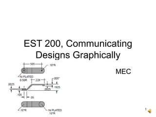
- 1. 1 EST 200, Communicating Designs Graphically MEC
- 2. 2 Contents • Engineering Communication. • Graphical Communication. • Sketching. • Engineering Drawings. • Fabrication Specifications. • Design Drawings. • Other Pictorial Representations.
- 3. 3 “The eyes believe themselves; the ears believe other people.” - A German Proverb. “One showing is worth a hundred sayings.” - A Chinese Proverb.
- 4. 4 How Engineers Communicate • Being able to communicate effectively a critical skill for engineers. • Communicate individually and as members of design teams. • Communicate through oral presentations, through written documents, and technical drawings. • Communication more effective through models or prototypes to demonstrate or evaluate design effectiveness.
- 5. 5 Design Drawings • Information created and transmitted in the drawing process. • Design drawings include sketches, freehand drawings, and computer-aided design and drafting (CADD) models. • Simple wire-frame drawings (such as stick figures) to solid models (3D figures). • Drawing, the process of putting “marks on paper.”
- 6. 6 • Marks include sketches and marginalia. • Sketches of objects and their associated functions. • Marginalia include notes in text form, lists, dimensions, and calculations written on margins. • Drawings enable a parallel display of information. Design Drawings
- 7. 7 Design Drawings • Drawings surrounded with adjacent notes, smaller pictures, formulas, and other pointers to ideas related to the object being drawn and designed. • Notes next to a sketch, a powerful way to organize information. • Graphic images to communicate with other designers, client, and manufacturing organization.
- 8. 8 Sketches and Drawings • Serve as a launching pad for a brand-new design. • Support the analysis of a design as it evolves. • Simulate the behavior or performance of a design. • Record the shape or geometry of a design.
- 9. 9 Sketches and Drawings • Communicate design ideas among designers. • Ensure that a design is complete. • Drawing and its associated marginalia remind of still-undone parts of that design. • Communicate the final design to the manufacturing specialists.
- 11. 11 Sketching • A powerful tool in design. • Permits designer to convey design ideas quickly and concisely. • Puts design thoughts on paper. • Starting point for other design activities. • Types of sketches: - orthographic sketches. - axonometric sketches. - oblique sketches. - perspective sketches.
- 12. 12 Orthographic Sketches • Projection of a single view of an object (such as a view of the front) onto a drawing surface. • 3D object in 2D. • Lay out of the front, right and top views of a part.
- 13. 13 Axonometric Sketches • Starts with an axis (corner of the part), typically a vertical line with two lines 30o from the horizontal. • Object then blocked in using light lines, with the overall size first. • Vertical lines darkened, followed by other lines. • All lines in the sketch either vertical or parallel to one of the two 30o lines. • Part details added last.
- 14. 14 Oblique Sketches • Most common type of quick sketch. • Front view blocked in roughly first, • Depth lines then added. • Details such as rounded edges added last.
- 15. 15 Perspective Sketches • Similar to oblique sketches. • Front view blocked in first. • A vanishing point chosen, projection lines drawn from the points on the object to the vanishing point. • Depth of the part then blocked in using the projection lines. • Details added finally to the part.
- 16. 16 Proportion Control • To show the relative sizes of parts, components, or features in a sketch. • Sketch designs on graph paper, because it is easier to control the relative sizes using the graph paper’s grid. • No need to use a ruler. • Good idea to think ahead of the components to be sketched before drawing actually begins.
- 17. 17 Proportion Control • First “block in” the overall length and width of a part. • Lay out the largest component first. • Then add details.
- 18. 18 Annotation • Annotations to be clear and easy to read. • Clear, easily read notes on sketches convey the meaning behind the sketched ideas. • Evenly spaced block letters are generally much clearer than cursive scribbles.
- 19. 19 Well annotated using block lettering. Clear, drawn proportionately.
- 20. 20 Fabrication Specifications • Need to communicate with the maker or manufacturer of the designed artifact. • Representations or descriptions of the designed object are included in the final design drawings. • To be complete, unambiguous, clear, and readily understood. • Design drawings prepared in accordance with relevant engineering practices and standards.
- 21. 21 Why Fabrication Specifications? • Design must perform as the designer intended. • Designer unlikely to be involved in the actual manufacture of the design result. • Designers may not be around to catch errors or to make suggestions. • Maker may be a different person. • Maker cannot turn around to seek clarification or ask on-the-spot questions.
- 22. 22 Properties of Fabrication Specifications • Device/product to be built by someone totally unconnected to the designer/design process. • Unambiguous - role and place of each and every component and part must be unmistakable. • Complete - comprehensive and entire in their scope. • Transparent – readily understood by the manufacturer or fabricator.
- 23. 23 Writing Fabrication Specifications • Prescriptive fabrication specification - specify a particular part and its number in a vendor’s catalog. • Procedural fabrication specification - specify a class of devices that do certain things. • Performance fabrication specification - leave it up to a supplier or the fabricator to insert something that achieves a certain function to a specified level.
- 24. 24 Design Drawings • Layout drawings: - to show the major parts or components of a device and their relationship. - drawn to scale, do not show tolerances. - subject to change as the design process evolves.
- 26. 26 Design Drawings • Detail Drawings: - show individual parts or components of a device and their relationship. - show tolerances, specify materials and any special processing requirements. - drawn in conformance with existing standards. - changed only when a formal change order provides authorization.
- 27. 27 Essential Components • Standard drawing views. • Standard symbols to indicate particular items. • Clear lettering and clear steady lines. • Appropriate notes and material specifications. • Title on the drawing. • Designer’s initials and date drawn. • Dimensions and units. • Permissible variations/tolerances.
- 29. 29 Design Drawings • Assembly Drawings: - show how individual parts/ components of a device fit together. - exploded view to show “fit” relationships. - bill of materials to identify components by part numbers or entries. - bill of materials include detail drawings if major views in detail drawings cannot show all required information.
- 31. 31 Tolerances • Impossible to make two objects exactly the same. • May appear to be the same due to our limited ability to distinguish differences at extremely small or fine resolution. • Tolerances to define permissible ranges of variation in critical or sensitive dimensions. • Tolerances prescribe limits.
- 32. 32 Standards • Articulate the best current engineering practices in routine or common design situations. • Indicate performance bars that must be met for drawings. • Individual standards written by professional societies and associations.
- 33. 33 Other Pictorial Representations • To extend limited human abilities to flesh out and communicate complicated pictures. • Circuit diagrams to represent electronic devices. • Flowcharts to represent chemical- engineering process plant designs. • Block diagrams to represent control systems.
- 34. 34 Comments “There are habits and styles of thought that are common to the design enterprise, there are also practices and standards that are unique to each discipline. It is the responsibility of the designer to learn and use them wisely.”
- 36. 36 Thank You