
Recommended
Recommended
More Related Content
What's hot
What's hot (20)
Similar to Designing, verifying and producing of a rescue robot prototype
Similar to Designing, verifying and producing of a rescue robot prototype (20)
Recently uploaded
Recently uploaded (20)
Designing, verifying and producing of a rescue robot prototype
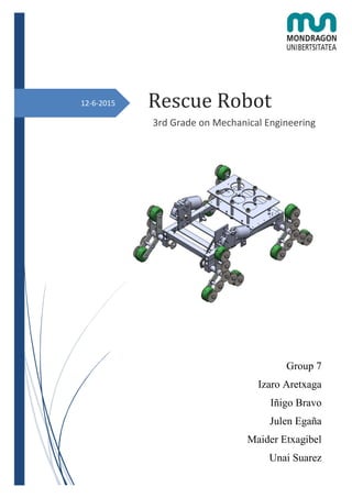
- 1. 12-6-2015 Rescue Robot 3rd Grade on Mechanical Engineering Group 7 Izaro Aretxaga Iñigo Bravo Julen Egaña Maider Etxagibel Unai Suarez
- 2. 7th GROUP Final Version Arrasate-Mondragon, 12 June of 2015
- 3. ABSTRACT POPBL VI Rescue robot I The Basque Government has contacted with the Mondragon Unibertsitatea to make a prototype of an autonomous rescue vehicle, which makes easier the rescue labor to the operators. This task must be completed fulfilling some compulsory specifications, such as go upstairs and downstairs. This document provides all the relevant information about the design, manufacture and assembly of the prototype. The first part of the project consisted of the design of a prototype which satisfied the specifications required. This stage, however, is centered on the manufacture and assembly of the robot. In order to make the vehicle go up and down the stairs in an autonomous way, the robot has been automated. Finally, to ensure the robot withstands an overweight when it remains still, static analyses of the critical elements have been carried out.
- 4. ABSTRACT POPBL VI Rescue robot II Eusko Jaurlaritza Mondragon Unibertsitatearekin jarri da kontaktuan salbamendu lanetan gizakiari lana errazten duen ibilgailu autonomo baten prototipoa burutzeko. Ibilgailu honek espezifikazio zehatz batzuk bete behar ditu, hala nola, eskailerak igo eta jaitsi. Dokumentu honetan prototipo horren diseinu, fabrikazio eta muntaiaren inguruko beharrezko informazioa aurkitzen da. Proiektuaren lehenengo atala, beharrezko espezifikazio guztiak betetzen dituen prototipoaren diseinuan oinarritu zen. Zati hau, aldiz, robotaren fabrikazio eta muntaian zentratzen da. Bestalde, robota automatizatu egin da, eskailerak igo eta jaitsi nahiz zirkuitu jakin bat burutzeko gai izateko. Robota geldi dagoela gainkarga bat aplikatzerakoan jasango duela ziurtatzeko, pieza kritikoekin analisi estatiko bat eraman da aurrera.
- 5. ABSTRACT POPBL VI Rescue robot III El Gobierno Vasco se ha puesto en contacto con la Universidad Mondragón para el diseño del prototipo de un vehículo autónomo de salvamento que facilite las labores de rescate al operario. Este vehículo debe de cumplir ciertas especificaciones, como subir y bajar escaleras. En este documento se facilita toda la información relevante sobre el diseño, fabricación y montaje del prototipo. La primera parte del proyecto consistió en el diseño de un prototipo que cumpla las especificaciones necesarias. La segunda parte, sin embargo, se centra en la fabricación y montaje del vehículo. La automatización del robot se ha llevado a cabo para conseguir que este sea capaz tanto de subir y bajar las escaleras como de completar un circuito específico. Por otra parte, se han llevado a cabo análisis estáticos de las piezas críticas del robot para asegurar que este es capaz de soportar una sobrecarga cuando está quieto.
- 6. INDEX POPBL VI Rescue robot IV INDEX 1. INTRODUCTION................................................................................................................. 1 1.1. Project Frame......................................................................................................1 1.2. Approach to the problem ....................................................................................5 1.3. Objectives ...........................................................................................................5 1.4. Planification........................................................................................................6 2. DEVELOPMENT OF THE PROJECT.................................................................................. 8 2.1. Redesigning of the robot .....................................................................................8 2.2. Manufacturing process ......................................................................................10 2.3. Assembly of the robot .......................................................................................17 2.4. Verification of the robot....................................................................................23 2.5. Automation of the robot ....................................................................................48 2.5.1. Elements.................................................................................................................... 49 2.5.2. Electric circuits.......................................................................................................... 51 2.5.3. Programming of the PLC .......................................................................................... 54 2.6. Budget ...............................................................................................................57 3. RESULTS ........................................................................................................................... 66 4. CONCLUSIONS................................................................................................................. 69 5. FURTHER RESEARCH..................................................................................................... 72 6. REFERENCES.................................................................................................................... 73
- 7. INDEX POPBL VI Rescue robot V FIGURE’S INDEX Figure 1 Different earth robots.....................................................................................................................1 Figure 2 First version design ........................................................................................................................3 Figure 3 Path geometry and dimensions.......................................................................................................6 Figure 4 Final design: Three-wheel system..................................................................................................8 Figure 5 Before and after star design............................................................................................................9 Figure 6 Structure of the final design ...........................................................................................................9 Figure 7 Before and after design of the gear shaft......................................................................................10 Figure 8 Process of copying holes..............................................................................................................16 Figure 9 Structure of the partial assembly..................................................................................................18 Figure 10 Chock and connection block assembled.....................................................................................18 Figure 11 Complete assembly of the structure ...........................................................................................19 Figure 12 Gears, wheels and bearing mounting .........................................................................................20 Figure 13 Transmission system design.......................................................................................................20 Figure 14 Motor and motor´s plate assembly .............................................................................................21 Figure 15 Three-wheel shaft's pinion .........................................................................................................21 Figure 16 Tensor design .............................................................................................................................22 Figure 17 Electronic components location .................................................................................................22 Figure 18 Finished assembly......................................................................................................................23 Figure 19 Model of the structure ................................................................................................................24 Figure 20 Stresses created due to the overweight.......................................................................................24 Figure 21 Stresses created bigger than 8 MPa............................................................................................25 Figure 22 Deformation appeared due to the overweigth ............................................................................26 Figure 23 Displacement formed because of the overweigth.......................................................................26 Figure 24 Motor´s placement in the structure.............................................................................................27 Figure 25 Stress concentrarion in the motor´s plate ...................................................................................27 Figure 26 Displacement created due to the motor´s weigth .......................................................................28 Figure 27 Three-wheel star model..............................................................................................................28 Figure 28 Forces produced in the clamping due to the overweight ............................................................29 Figure 29 Tension concentration of the three-wheel star ...........................................................................29 Figure 30 Tension concentration in the radious of the stars .......................................................................30 Figure 31 Tension values without radious..................................................................................................30 Figure 32 Tension values with radious.......................................................................................................31 Figure 33 Displacement suffered by the three-wheel star ..........................................................................31 Figure 34 Free body diagram going upstairs position ................................................................................33
- 8. INDEX POPBL VI Rescue robot VI Figure 35 Free body diagram going upstairs ..............................................................................................34 Figure 36 Working cycle of the robot ........................................................................................................36 Figure 37 S-N Diagram of the tube ............................................................................................................36 Figure 38 Haigh´s diagram.........................................................................................................................37 Figure 39 Equivalent strees calculation......................................................................................................38 Figure 40 Limit range of the stress.............................................................................................................40 Figure 41 Lifetime of the tube upstairs ......................................................................................................40 Figure 42 Free body diagram downstairs position .....................................................................................41 Figure 43 Free body diagram going downstairs .........................................................................................42 Figure 44 Lifetime of the tube downstairs..................................................................................................43 Figure 45 Position of the strain gage and indicator ....................................................................................45 Figure 46 Three element rosette gage.........................................................................................................45 Figure 47 Robot with the overweight of 70kg............................................................................................46 Figure 48 Position of the principal strains..................................................................................................47 Figure 49 Indicator above the sheet............................................................................................................48 Figure 50 Remote control...........................................................................................................................49 Figure 51 LDR electric circuit....................................................................................................................51 Figure 52 Power scheme ............................................................................................................................53 Figure 53 Order scheme .............................................................................................................................54 Figure 54 Programmed circuit....................................................................................................................55 Figure 55 First level automatic mode GRAFCET......................................................................................55 Figure 56 First level manual mode grafcet.................................................................................................56 Figure 57 First level automatic mode GRAFCET......................................................................................57 Figure 58 First level lights module GRAFCET..........................................................................................57 Figure 59 Distribution of the different costs [€].........................................................................................64 Figure 60 Distribution of the different costs [€] without some electric components..................................65 Figure 61 Robot’s final design ...................................................................................................................66
- 9. INDEX POPBL VI Rescue robot VII TABLE’S INDEX Table 1 Decision matrix of different earth robots.........................................................................................2 Table 2 Motor chosen decision matrix .........................................................................................................4 Table 3 Manufacturing of the robot’s parts ................................................................................................11 Table 4 Parts needed to assembly the structure..........................................................................................17 Table 5 Parts needed to assembly the structure ..........................................................................................19 Table 6 Results of the upstairs static analysis ............................................................................................34 Table 7 Applied coefficient and the choosing criteria................................................................................39 Table 8 Results of the downstairs static analysis........................................................................................41 Table 9 Elements of power and order circuits ............................................................................................52 Table 10 Inputs and outputs of the PLC .....................................................................................................53 Table 11 Electrical component´s total price ...............................................................................................58 Table 12 Commercial element´s cost .........................................................................................................59 Table 13 Machine taxes..............................................................................................................................59 Table 14 Raw material and machining cost................................................................................................60 Table 15 Manual operations costs ..............................................................................................................61 Table 16 Preparation time cost ...................................................................................................................62 Table 17 Unexpected operations cost.........................................................................................................63 Table 18 Final budget of the manufacturing of the robot ...........................................................................63 Table 19 Results of the theoretical analysis ...............................................................................................66 Table 20 Comparison and error between the theoretical and practical results ...........................................67
- 10. INTRODUCTION POPBL VI Rescue robot 1 1. INTRODUCTION Dangerous situations, such as nuclear explosions, earthquakes, inundations... can occur anywhere and is necessary to be prepared to cope with them. In order to be able to work in those situations, different types of robots and drones are used. The most important advantage of these vehicles is that they make possible not to put people’s life at risk, arriving to places with a difficult orography, what could be dangerous to the operator. Moreover, they are also used to carry on heavy objects or first aid kits. That’s why the Basque Government asked Mondragon Unibertsitatea about the possibility of manufacturing a new robot. The objective of this self-sufficient vehicle is to make rescue group’s work easier, ensuring the security of the people and providing new applications. Therefore, it was decided to design and manufacture a rescue robot. With the aim of improving the design done in the first part of the project, on the following report, all the information about the redesign, the manufacture and testing of the robot can be found. 1.1. Project Frame When the project was presented, the first task was to carry out a market research in order to know which type of robots there were depending on different factors. One example of those factors is the environment in which they were going to work, such as air, water and earth. Taking into account the specifications needed to be accomplished, the project was centered on the earth robots. Once having decided the type of robot, three different vehicles were analyzed: zipper, three-wheel and caterpillar (Figure 1). If more information is needed, see appendix A. Figure 1 Different earth robots
- 11. INTRODUCTION POPBL VI Rescue robot 2 As the task needed to be carried out is to design, manufacture and test a prototype, the first step was to consider different possible designs and movement types of the robot and choose the most appropriate one. This work was accomplished by using a decision matrix, shown in table 1, where it is possible to see that the design chosen was the three-wheel system. The main characteristic of this type of robot is that the three-wheel conjunct rolls free in its shaft in order to go up and down the stairs. Table 1 Decision matrix of different earth robots Importance Zipper Three-wheel Caterpillar Ability to go upstairs 3 1 3 2 6 2 6 Efficiency 3 1 3 3 9 2 6 Ability to turn 3 2 6 2 6 2 6 Complexity of the system 2 2 4 2 4 1 2 Stiffness 2 1 2 2 4 3 6 Price 2 2 4 2 4 2 4 Manufacturing and assembly 3 3 9 2 6 2 6 Total 31 39 36 Step by step the design has been improved until reaching the first version (Figure 2). After that, some redesigns have been developed until achieving the final design. The details of the redesigning have been explained in the development of the project.
- 12. INTRODUCTION POPBL VI Rescue robot 3 Figure 2 First version design In what the dimensioning and the insurance of the good accomplishment of the robot is concerned, the static analysis of three critical parts of the robot was carried out: three-wheel shafts, can store and structure. In respect of the three-wheel shafts, it was obtained that the most critical situation was when the robot remains still and must withstand four times its weight. Taking this and the maximum allowed working deformation into account, the dimensioning of the supports was made. In order to carry it out, the working requirements were also taken into account. Furthermore, an analysis of the comparison between different materials was carried out, reaching to the conclusion that the most appropriate material was aluminum. To prove the stability of the robot and ensure it was not going to rollover, the maximum angle in which the robot will have to work was 77.89º. In what the motors is concerned, three different types of motors were analyzed, asynchronous motors, servo motors and direct current motors. A matrix was done in order to know which the motor that complied, in the best way, the needed characteristics was (Table 2). The conclusion reached was that the most appropriate type of motor for this case was the direct current motor.
- 13. INTRODUCTION POPBL VI Rescue robot 4 Table 2 Motor chosen decision matrix Importance Asynchronous Serbo Direct current Size and weight 5 2 10 3 15 4 20 Velocity control 3 3 9 5 15 3 9 Price 4 4 16 2 8 3 12 Power 5 3 15 2 10 4 20 Maintenance 2 3 6 4 8 5 10 Noise 2 2 4 2 4 2 4 Consumption 3 2 6 4 12 3 9 Efficiency 3 3 9 4 12 2 6 Total 75 84 90 After having chosen the motor, it was proved that the one chosen was able to give the torque necessary to work in an adequate way. During the entire project, and in order to ensure the perfect quality of the robot, a FMEA was carried out.
- 14. INTRODUCTION POPBL VI Rescue robot 5 1.2. Approach to the problem After accepting the request of the public administration it has been decided to go ahead with the project. The length of the project is one year, when the prototype will be designed, manufactured and tested. This project consists of two stages. The first one was focused on the design of the robot, as it is explained in the previous part. This stage, however, consists of the manufacturing and testing of the robot designed, making all the improvements necessary in order to obtain the best result. 1.3. Objectives The main objective of this second part of the project is to redesign, manufacture, assembly and test the robot. To reach this principal objective, some supporting objectives must be completed: Design, develop and assembly an automation system for the robot in order to be autonomous. Verify the critical parts of the robot in order to know if the robot is going to work in a proper way even in the critical situation. The robot must fulfill the following specifications: The budget of the project must be of 600€. Movement The robot should be able to climb three stairs followed. The stairs dimensions: 17 mm high and 300 mm of horizontal part. Time to climb each stair: 30s. Stiffness Load to be transported: o When the robot is not moving (Steady state): Each project team will have to set a unitary deformation range for the critical part of the robot, taking into consideration that the robot must be able to withstand a load of four times its own weight.
- 15. INTRODUCTION POPBL VI Rescue robot 6 o When the robot is moving it must be able to work in continuous mode and move a load and a volume of six filled refreshment cans. Automation The robot should be controlled by an OMRON PLC. The remote control will be by cable. The robot should operate connected to a standard electric plug (the use of batteries is not allowed). The robot must be able to perform automatically a previously defined path. The dimensions of the path are shown in the figure below (Figure 3). Figure 3 Path geometry and dimensions For safety reasons, the robot working slope is limited to 40. So, if the robot finds in its way any obstacle that demands a higher slope, it must stop. If your robot has some digital output free, you can consider installing: automatic light control, add a buzzer to switch on whenever the robot is moving. 1.4. Planification To carry out the phases of the project in the correct way, a good planning of the tasks is necessary. In order to be the most effective possible, the different activities that are going to be performed during the project have been analyzed. A coordinate has been assigned to each task, in addition to their length (Appendix B).
- 16. INTRODUCTION POPBL VI Rescue robot 7 This second part of the project is divided into different tasks. The first ones are planned to center and limit the problem in order to make easier to carry out the project. The rest of the tasks are divided into practical and theoretical ones, which are developed simultaneously, in order to carry out the project in the best way possible. This planning will have to be adjusted during the project, depending on the workload and it is follow up. In order to compare the planning done in the first stage of the project with the one followed really, the real planning has been represented in another colour.
- 17. DEVELOPMENT OF THE PROJECT POPBL VI Rescue robot 8 2. DEVELOPMENT OF THE PROJECT The development of this project is directly related with the previously explained objectives and specifications. The following part contains all the necessary information to understand the robot behavior under different situations, the automation, the manufacturing and the assembly of the robot. Also, includes the budget calculus, to have a real idea of the robot cost. 2.1. Redesigning of the robot Before reaching the final version some changes have been done. This robot has some critical parts that must work with high precision in order to get a perfect movement. These parts have been optimized as much as possible since the first design of the project. Mainly three parts have been modified: stars, wheel shafts and the structure (Figure 4). Figure 4 Final design: Three-wheel system One of the most important parts is the star, in which the shafts of the gears are introduced. In this case, the dimensions have been reduced as much as possible to ensure the appropriate climbing of the stairs. The old and the new versions can be seen in figure 5.
- 18. DEVELOPMENT OF THE PROJECT POPBL VI Rescue robot 9 Figure 5 Before and after star design Another essential part, which has been redesigned, is the structure of the robot. It must support the weight of all the electric components and the cans without deforming more than a certain value, so a stronger design has been done assembling some nerves to the structure. The new structure is shown in figure 6. Figure 6 Structure of the final design The last critical parts are the shafts of the stars. As the aim of those parts is to transmit the movement from the gears to the wheels, this transmission must be as precise as possible. To achieve it, the design of that transmission has been changed. The connection between the shafts and the gear has been done by pins, not allowing the gear slide in the shaft. Both designs are shown in figure 7.
- 19. DEVELOPMENT OF THE PROJECT POPBL VI Rescue robot 10 Figure 7 Before and after design of the gear shaft 2.2. Manufacturing process One of the main objectives of this part of the project is to manufacture the rescue robot. To achieve an optimum manufacturing some important details must be taken into account. All the manufacturing process has been summarized in the table 3.
- 20. DEVELOPMENT OF THE PROJECT POPBL VI Rescue robot 11 Table 3 Manufacturing of the robot’s parts Part Name of the part Reference in plans Used machines Processes Long square tube EI_G07_001 Mechanical saw Cut all the square tubes with the adequate length Drill Make all the holes. To make the keyholes, make a hole in each corner and join them with a rasp Short square tube EI_G07_002 Mechanical saw Cut all the square tubes with the adequate length Drill Make all the holes Auxiliary shaft EI_G07_003 Mechanical saw Cut all the cylinders longer than the final size to be able to mechanize them Lathe Mechanize all the parts in the conventional lathe Drill Make all the holes
- 21. DEVELOPMENT OF THE PROJECT POPBL VI Rescue robot 12 Handmade Thread one hole Three wheel shaft EI_G07_006 - This part will be manufactured in a company out of the university Framing square EI_G07_005 Mechanical saw Cut all the parts with the correct dimensions Drill Make all the holes Main shaft EI_G07_004 Mechanical saw Cut all the shafts longer than the final size to be able to mechanize them Lathe Mechanize all the pieces in the conventional lathe Drill Make all the holes Handmade Thread one hole Three wheel tube EI_G07_007 Mechanical saw Cut all the parts longer than the final size to be able to mechanize them
- 22. DEVELOPMENT OF THE PROJECT POPBL VI Rescue robot 13 Chock EI_G07_008 Mechanical saw Cut all the square tubes with the correct dimensions Drill Make all the holes Connection block EI_G07_009 Mechanical saw Cut all the parts longer than the final size to be able to mechanize them Milling Make the internal hole Drill Make all the holes Handmade Thread all the holes Base sheet EI_G07_010 Shears Cut the sheet with the correct dimensions Drill Make all the holes
- 23. DEVELOPMENT OF THE PROJECT POPBL VI Rescue robot 14 Motor plate EI_G07_011 Shears Cut the plate with the correct dimensions Milling Make all the holes and the keyholes Nerve EI_G07_012 Shears Cut the plate with the correct dimensions Drill Make all the holes Tensor plate EI_G07_013 Shears Cut the plate with the correct dimensions Milling Make all the holes and the keyholes Tensor shaft EI_G07_014 Mechanical saw Cut all the shafts longer than the final size to be able to mechanize them Lathe Mechanize all the parts Drill Make all the holes
- 24. DEVELOPMENT OF THE PROJECT POPBL VI Rescue robot 15 Sheets shaft EI_G07_015 Manual saw Cut all the parts with the correct length Holes sheet EI_G07_016 Shears Cut the sheet with the correct dimensions Drill Make all the holes Star EI_G07_017 - This part will be manufactured in a company out of the university Wheel EI_G07_018 Lathe Cut all the wheels, mechanize then and make the central hole Drill Make all the holes
- 25. DEVELOPMENT OF THE PROJECT POPBL VI Rescue robot 16 Handmade Stick the external rubber with super glue. In what the structure is concerned, all the elements are tied with screws, that’s why all the holes between the parts must be concentric. To achieve it, the holes of some elements have been copied on others, that is to say, the holes of the part are going above others are the ones that have been copied (Figure 8): Framing squares on long and short tubes Nerves on long tubes Chocks and connection blocks on long tubes Base sheet on long tubes Figure 8 Process of copying holes With regard to the main and auxiliary shafts, they have to move at the same time as the gears and in the case of the main shafts, with the wheels too. That is why both elements have been assembled to the shaft using pins. To achieve that union the common holes of the shafts with the other two elements have been done with those assembled. After that, the pins have been introduced immediately because the hole tends to close.
- 26. DEVELOPMENT OF THE PROJECT POPBL VI Rescue robot 17 Therefore, the holes of the gears and the shafts must be in the center. To ensure a proper functioning those holes have been done in the lathe. 2.3. Assembly of the robot Once all the parts have been manufactured, the next step is to assembly the robot. This process will be done in three parts: the structure, the three-wheel stars and the transmission. Structure The structure is a square frame stiffened with some nerves assembled above four blocks. The parts needed are shown in the table 4. Table 4 Parts needed to assembly the structure Part Quantity Dimensions[mm] Long square tube 2 25x25x3x500 Short square tube 2 25x25x3x300 Framing square 4 30x30x2x25 Nerves 2 30x5x300 Chock 4 25x25x3x50 Connection block 4 40x40x30 First of all, a square frame has been mounted using the long and short tubes and fixing them to the framing squares and screws. After that, the nerves have been added to the structure between the two long tubes using screws. This will give the stiffness needed to the structure (Figure 9).
- 27. DEVELOPMENT OF THE PROJECT POPBL VI Rescue robot 18 Figure 9 Structure of the partial assembly Finally, the square frame has been assembled to the connection blocks. Between the two elements some chocks have been added in order to give height to the structure with the aim not to hit the stairs. This connection has been done with screws too (Figure 10). Figure 10 Chock and connection block assembled The complete assembly of the structure is the next one (Figure 11). The only thing missing is to add the can collector that will be done at the end. The next step will be the assembly of the three-wheel star.
- 28. DEVELOPMENT OF THE PROJECT POPBL VI Rescue robot 19 Figure 11 Complete assembly of the structure Three-wheel stars The robot is composed by four three-wheel stars, which are made by two parts with star form and some shafts introduced between those. The entire conjunct has been assembled above circular tubes where he three-wheel shaft have been introduced. The parts needed are shown in the table 5. Table 5 Parts needed to assembly the structure Part Quantity Dimensions[mm] Star 8 Not home manufacturing Main shaft 12 Ø12x73.5 Auxiliary shaft 12 Ø12x73.5 Three-wheel shaft 4 Ø18x160 Circular tube 4 Ø25xØ20x120 Wheel 12 Ø70x31 First of all, friction bearings have been introduced in the stars and in the circular tube. As the shafts have to roll inside the stars, those elements are indispensable. After that, the wheels have been assembled to the main shafts using pins and main and auxiliary shafts have been introduced in the stars. At that point, the shafts have been fixed axially using threaded pins. Therefore, the gears have been mounted in all the shafts using pins (Figure 12).
- 29. DEVELOPMENT OF THE PROJECT POPBL VI Rescue robot 20 Figure 12 Gears, wheels and bearing mounting Finally, the circular tubes have been introduced in the center hole of the star and the three-wheel shaft inside the tube. Transmission A transmission system has been used to bring the movement from the two motors to the wheels. The composition of that system has been made by three pinions and two chains for each motor (Figure 13). Figure 13 Transmission system design The first step to mount the transmission has been to assemble the motor´s plates. The fixing of those parts has been made by screws. Once the plats have been mounted, the motors have been fixed there by screws (Figure 14).
- 30. DEVELOPMENT OF THE PROJECT POPBL VI Rescue robot 21 Figure 14 Motor and motor´s plate assembly The next step has been to introduce the three-wheel shafts in the tubes. Those shafts have the gears assembled already, so the pinions have been mounted in the opposite end of the shafts using keys and fixing them with thread pins. At that point the four three-wheel shafts have been completely assembled (Figure 15). Figure 15 Three-wheel shaft's pinion For the optimum functioning of the transmission is essential to have the chain tensed. That is why a tensor system has been assembled in the structure and each tensor is made by two plates, the tensor shaft and the pinion (Figure 16).
- 31. DEVELOPMENT OF THE PROJECT POPBL VI Rescue robot 22 Figure 16 Tensor design First of all, the tensor plates have been mounted in the keyholes of the structure. Those keyholes have been machined in order to adjust the tension of the chain, so the plates have been mounted in order to have the most margins to tense the chain. Therefore, the shaft has been introduced into the two plates having mounted some bearings there and finally the pinions have been assembled in the shafts using some pins. Finally, the chains have been assembled in the pinions and tensed with the tensor. The can collector has been mounted after the transmission system assembly. Regarding the electric components, they have been mounted in the backside of the robot in a standardized DIN rail (Figure 17). Figure 17 Electronic components location
- 32. DEVELOPMENT OF THE PROJECT POPBL VI Rescue robot 23 The finished assembly is shown in the figure 18. Figure 18 Finished assembly 2.4. Verification of the robot To verify that the robot is working in a proper way is necessary to know how the different parts behave in the specify process. That work have been done carrying out a structural analysis using finite elements method calculating the displacements, stresses and unitary deformations and a fatigue analysis of the critical parts of the robot to approach the lifetime. The results of the structural analysis have been compared with the ones calculated using strain gages and an indicator. As only one of the critical parts suffer fatigue that is the part have been analyzed. Theoretical structural analysis First of all, the critical parts have been chosen. In the first part of the project the chosen elements as the most critical ones were the next ones: the structure, the bolts of the cans and three-wheel shafts. Nevertheless, when the redesigning has been done, it has been realized that the shafts weren’t the elements which suffer the most, but the three-wheel tube. Besides, the can´s bolts have been neglected because they only have to support the can’s weight, apart from being over dimensioned, so another part has been chosen such as the motor plate. As it has said in the specifications, the robot must withstand an overweight of four times its weight. It has been decided to make all the analysis in that condition,
- 33. DEVELOPMENT OF THE PROJECT POPBL VI Rescue robot 24 because is the most critical one. The materials used to manufacture the robot are aluminum (6063 T6) and steel (F-1045). The first part analyzed have been the structure. Figure 19 shows the model of the structure of the system in order to do the theoretical analysis. Figure 19 Model of the structure It has been decided that the overweight (70 kg), which is four times the weight of the robot, will be placed on the bottom plate. Figure 20 shows the stresses created by the applied overweight. Figure 20 Stresses created due to the overweight The tension concentration in the structure is not very big, despite the applied overweight of 70kg. The maximum tension concentration will be in the corners of sheet and in the joint with the structure. With the aim of concreting more the critical zones, it has been set a value of 8 MPa shown in the figure 21. In this way it can be seen that the tension concentration is in the position told before, which will be the best to attach the strain gage that have been explained later.
- 34. DEVELOPMENT OF THE PROJECT POPBL VI Rescue robot 25 Figure 21 Stresses created bigger than 8 MPa It can be seen that there is a high tension concentration in each connection block which are clamped. This phenomenon happens because the software used needs a clamping in order to carry out the simulation. Those clamping suffer a crushing because of the overweight, but this tension concentration is neglected for the theoretical analysis because physically this is not happening. Apart from that, the maximum deformation of the system has been estimated. A strain gage is a device used to measure deformation on an object. The gage is attached to the object by a suitable adhesive and as the object is deformed, the foil is deformed, causing its electrical resistance to change. This resistance changes, usually measured using a Wheatstone bridge, is related to the strain. Figure 22 shows the deformation suffered by the system as a result of the overweight applied. Besides, the maximum unitary deformation appears where the maximum tension is situated, that will be 6 105.189 mm.
- 35. DEVELOPMENT OF THE PROJECT POPBL VI Rescue robot 26 Figure 22 Deformation appeared due to the overweigth Therefore, the bottom plate will deform as figure 23 shows. It can be said that the system is stiff enough taking into account that the maximum displacement established was just one millimeter. In appendix C can be seen more detailed the aspect that the structure will have after applying the overweight. Figure 23 Displacement formed because of the overweigth The next part that has been analyzed are the motor plates. Those parts have been chosen because they must withstand the weight of the motor while it is moving. This part will be fixed to the structure with screws, figure 24.
- 36. DEVELOPMENT OF THE PROJECT POPBL VI Rescue robot 27 Figure 24 Motor´s placement in the structure If this part breaks down, the robot will not be able to move because the transmission will be lost. Figure 25 shows the tension concentration in the plate of steel, in consequence of the motor’s weight (1.5kg) that will be of 112 MPa. That will be very concentrated in edges of the hole. In addition, the unitary deformations will be in the same place, as it can be seen in appendix C. Figure 25 Stress concentrarion in the motor´s plate The weight of the motor apart from creating internal tensions, also creates a deformation as it is shown in figure 26. A big deformation will not be appropriate and if it happens, it will be necessary to find a solution. In this case, the plate will deform 0.1 mm so the motors will work correctly.
- 37. DEVELOPMENT OF THE PROJECT POPBL VI Rescue robot 28 Figure 26 Displacement created due to the motor´s weigth Finally, as it has been said before, the tubes are going to suffer when the overweight is placed on the system. Figure 27 shows the three-wheel star model, where the tube is placed. The tube is the most critical element in the system, because if it breaks down when the overweight is placed, the robot will not be able to complete its function. This would happen because the structure will uphold in the shaft, which is inside the tube, and it wouldn´t rotate because of the force produced by the weight. Figure 27 Three-wheel star model Before doing the theoretical verification of the maximum tensions and displacements, the force in each joint of the structure with the three-wheel star model must be known. In order to obtain it, figure 28 shows the forces created by the overweight in each clamping.
- 38. DEVELOPMENT OF THE PROJECT POPBL VI Rescue robot 29 Figure 28 Forces produced in the clamping due to the overweight Once the forces are known, the verification of the three-wheel star model has been done, exactly the tube verification. For this analysis 271 N force is going to be used, because is the most critical one. However, it can be seen in the appendix C a comparison between the three-wheel stars, depending on the force that corresponds to each one. The maximum punctual tension is shown in figure 29 with the aim of proving that the tube endures the overweight. The tube suffers a maximum stress of 29 MPa. Figure 29 Tension concentration of the three-wheel star
- 39. DEVELOPMENT OF THE PROJECT POPBL VI Rescue robot 30 Another important detail is what happens in the stars. As it can be seen in the figure 30 there is a big tension concentration in the edges of the stars. This happens because they do not have the needed radius and the tension concentration in that point is bigger. Figure 30 Tension concentration in the radious of the stars The tube is the first element which is going to suffer the force created by the overweight. This is logical, because is the element of the three-wheel star which is in contact with the structure. After the tube, the star will start suffering in its edges. Figure 31 shows the tension in the edges of the star and it can be seen that the lower edge is which suffers more with 24 MPa. This happens because when a weight is applied, the legs tend to open. Figure 31 Tension values without radious
- 40. DEVELOPMENT OF THE PROJECT POPBL VI Rescue robot 31 Taking these tensions into account, it has been decided that a radius is necessary in the three edges of the stars in order to decrease the tension concentration in those edges. In this way, the star will be more secure against the force created by the overweight (Figure 32). Figure 32 Tension values with radious Therefore, figure 33 shows the displacement of the assembly taking into account the forces that produces the overweight in the structure. Figure 33 Displacement suffered by the three-wheel star Once the verification of the overweight has been completed, the robot will be able to complete its cycle correctly. As it has been said before, while the robot is transporting the cans upstairs and downstairs it will suffer from fatigue. This fatigue
- 41. DEVELOPMENT OF THE PROJECT POPBL VI Rescue robot 32 will only affect to the tubes, because those are the only ones which suffers a changing force. The tubes are going to suffer highest force when the robot is going downstairs, because the shafts will incur impact. Fatigue analysis The three wheel tube is one of the critical elements of the robot. In order to know which is going to be its lifetime, the calculus of the fatigue has been carried out. The fatigue determines the lifetime of an element that suffers from repetitive forces. The limit lifetime the robot must endure is a million of cycles, taking into account that a cycle is a stair going up or down. The forces the tube suffers vary depending on the robots working position. That’s why the three situations in which the robot will work are going to be analyzed, doing the circuit in a plane surface and going up and down the stairs. There are three methods to perform the fatigue analysis, and as in this project what it is wanted to obtain is the lifetime of the component knowing its nominal stress, the one used is the S-N model. The S-N diagram makes possible to obtain the number of cycles a component can work depending on the stress at which it is submitted. The first situation that has been analyzed is when the robot is doing the circuit in a plane surface. As the tube does not work turning on itself and it does not suffer any impact, it will not suffer from fatigue when it is in a plane surface, given that in that situation the force supported by the tube will be constant. The second situation in which this analysis has been used is when the robot is climbing the stairs. As the back wheel's tube and the ones of the front do not suffer the same magnitude of force, the most critical ones have been analyzed. In this case, the back wheel’s tubes are the ones that suffer the most. This happens because in this case, they have to withstand almost all the weight of the robot when this is going up the stairs (motors and electronic components). The tubes suffer from bending stress, which will be caused by the strength of the weight of the three-wheel stars situated in one side of the tubes while the other part is
- 42. DEVELOPMENT OF THE PROJECT POPBL VI Rescue robot 33 built in the connection block. In order to calculate the stress originated, this formula is used. I rrM io (1) When, 4 o i mmInertia: mmtubetheofradiousOuter: mmtubetheofradiousInner: NmtorqueBending: MPastressBending: I r r M In order to calculate the torque produced in bending while climbing the stairs, it is necessary to know which the load that causes it is, which is obtained from static analysis (Figure 34). Figure 34 Free body diagram going upstairs position When, W1: Weight of the robot W2: Weight of the cans F1: Force suffered by the backside tubes F2: Force suffered by the front tubes
- 43. DEVELOPMENT OF THE PROJECT POPBL VI Rescue robot 34 After doing all the calculus that are necessary, it is obtained that the force suffered by each tube is the next that is shown in the table 6. Table 6 Results of the upstairs static analysis 1W [kg] 2W [kg] 1F [N] 2F [N] 17.5 2.5 62.86 35.14 Once having calculated the strength suffered by the tube, the bending stress have been calculated. This stress calculated is the one the tube suffers in the least critical situation, given that. MPa1.318 11320.77 10)-(12.59562.86io min I rrM S (2) In the case of the inertia, is the one regarding to the axis perpendicular to the axis of the tube. 4 444 i 4 o mm7711320 64 )20-(25π 64 π dd I (3) The most critical situation is when the collision occurs. This phenomenon appears due to the impact that the wheels have with the stairs when the three wheel system is rotating (Figure 35). Figure 35 Free body diagram going upstairs
- 44. DEVELOPMENT OF THE PROJECT POPBL VI Rescue robot 35 In order to calculate the force suffered by the tube in that situation, the crash equation has been used. N85.183 050 40cos6.020cosm 11 T .t θv F (4) When, [s]crashofTime s m hcratheofVelocity [Kg]robottheofMassm [N]crashtheinForce 1 1 T t sv F Knowing that the force just obtained is the one that suffer both back tubes, the force suffered by each tube will be 91.925 N. Both, the time of crash and the velocity of the robot before the crash, have been obtained by making assumptions. In what the time of crash is concerned, the hypothesis made is that the time of crash is really brief, assuming it is nearly zero. The velocity of the robot before the crash, however, has been decided taking into account the maximum velocity which is 1.137 m/s, that is to say the velocity of the crash must be lower than this. MPa928.1 11320.77 10)-(12.59591.925io max I rrM S (5) Once having calculated the maximum and the minimum stresses, it is possible to calculate the medium and alternate stresses of the component, which are necessary to know which the lifetime of the tube is. After that, the working cycle of the robot have been concreted (Figure 36). 1.623MPa 2 m minmax m S SS S (6) 0.305MPa 2 a minmax a S SS S (7)
- 45. DEVELOPMENT OF THE PROJECT POPBL VI Rescue robot 36 Figure 36 Working cycle of the robot Once the medium and the alternate stresses have been calculated, the next step will be to make the S-N diagram of the material before characterizing the component. However, this will be in a process where the material’s lifetime would be infinite without exceeded a certain force. This is the case, for example, of the steels. But in this case the material is aluminum, a material that in any case its lifetime will be finite. The stress calculated at 107 cycles (S7) is shown in the next figure (Figure 35). This stress has been obtained from the program CES. Figure 37 S-N Diagram of the tube It is possible to see that the more cycles the component supports, its lifetime decreases. As it can be seen, the previous S-N diagram is the one that corresponds to a stress ratio of -1. The stress ratio is the ratio of the minimum stress experienced during a
- 46. DEVELOPMENT OF THE PROJECT POPBL VI Rescue robot 37 cycle to the maximum stress experienced during a cycle. The stress ratio is obtained with the next equation: max min ratioStress S S (8) The most common values for the stress ratio are 0 and -1, that is to say, when the Smin is zero or when Smin and Smax have the same value, but one been negative. As in this case the component does not accomplish any of these characteristics, the stress ratio has been calculated. 68.0 max min S S (9) As the only two regulated S-N diagrams are the ones that correspond to the stress ratios 0 and -1, it is necessary to use the Haigh’s diagram in order to obtain the stress value that will have a stress ratio of -1 and the same lifetime. To achieve that, the first step is to locate the point A which is obtained joining the medium and alternate stresses of the tube. After that, the equivalent stress has been calculated which will has the same lifetime and a ratio of -1 (Figure 38). That is because is located in the same line of the stress calculated previously and in the vertical axis, where Sm is zero so the Smax and the Smin will be same in value but contrary in signs. Figure 38 Haigh´s diagram The equivalent stress is the value which is going to be used in the S-N diagram. The next figure has been used to obtain the equivalent stress of the tube (Figure 39).
- 47. DEVELOPMENT OF THE PROJECT POPBL VI Rescue robot 38 Figure 39 Equivalent strees calculation After doing the necessary calculations, the equivalent stress has been obtained. MPa306.0eq S As it has been said before, the stress calculated is the one that corresponds to the material, so, in order to calculate the stress of the component, some coefficients must be applied (Table 7) [1]. As the stress value of the material corresponds to 107 cycles, the coefficients have been also applied to this value. As it is a very difficult job to obtain the coefficients that correspond to the aluminum, the ones used with steels have been used. This is because it has been supposed that it is better to apply a no very exact coefficients better than not applying any. In order to obtain the stress of the component the next equation has been used. f vmftds k Scccccc S 7' 7 (10)
- 48. DEVELOPMENT OF THE PROJECT POPBL VI Rescue robot 39 Table 7 Applied coefficient and the choosing criteria Name of coefficient Choosing criteria Value Surface finish cs Machined and break resistance 565 MPa 0.84 Dimensions and geometry cd Medium 0.85 Working way ct Testing and working in bending 1 Reliability cf The stress considered is the one of the limit of the range, so the reliability is maximum (1) 1 Surface treatments cm Any surface treatment 1 Multiple effects cv Fretting, impacts, corrosion 0.75, 0.7, 0.8 Notch effect kf Any sensibility to notches 1 (1) The stresses of the stress range of the S-N diagram vary depending on the reliability of the component. As in this case the stress used has been the one that corresponds to the line below, the one that has a reliability of 100%, the value of the reliability coefficient is 1. After obtaining all the coefficients, the previous equation has been applied in order to calculate stress of the component. MPa89.24 7' 7 f vmftds k Scccccc S (11)
- 49. DEVELOPMENT OF THE PROJECT POPBL VI Rescue robot 40 In the next figure it is possible to see which the limit of the stress range of the component is (Figure 40). Figure 40 Limit range of the stress Once the limit of the stress value has been calculated, the last part is to introduce the equivalent stress in the S-N diagram in order to know where does it join with the limit of the stress range and in that way calculate the lifetime of the tube (Figure 41). Figure 41 Lifetime of the tube upstairs
- 50. DEVELOPMENT OF THE PROJECT POPBL VI Rescue robot 41 As it is possible to see in the previous figure, the tube will last 7 102N cycles. The third situation that has been analyzed is when the robot is going down the stairs. The process that must be carried out in order to obtain the lifetime of the tube is exactly the same to the one used when going up the stairs. The first task is to calculate the force that causes the torque in bending. To do so, the next free body diagram has been used (Figure 42). Figure 42 Free body diagram downstairs position After doing all the calculus that are necessary, it is obtained that the force suffered by each tube is the next that is shown in the table 8. Table 8 Results of the downstairs static analysis 1W [kg] 2W [kg] 1F [N] 2F [N] 17.5 2.5 62.86 35.14 Knowing this force, is possible to calculate the minimum stress suffered by the tube, which is the one that suffered when going down the stairs. This minimum stress is the same to the one calculated when going up the stairs. 1.318MPa 11320.77 10)-(12.52562.86r io min I rM S (12)
- 51. DEVELOPMENT OF THE PROJECT POPBL VI Rescue robot 42 As in the previous case, the maximum stress is the one obtained from the force the tube suffer when the collision occurs. Figure 43 Free body diagram going downstairs The force is calculated with the next equation. N76.275 0.05 40cos9.020cosm 21 T t θv F (13) Knowing that the force just obtained is the one that suffer both back tubes, the force suffered by each tube will be 137.88 N. Once having obtained collision force, the maximum stress has been calculated. MPa785.5 11320.7 10)-(12.525137.88r io max I rM S (14) The next step is to calculate the alternate and the medium stresses. MPa55.3 2 m minmax m S SS S (15) MPa23.2 2 a minmax a S SS S (16) In order to obtain the lifetime of the tube when going down the stairs, it is necessary to calculate the stress ratio of the component. 22.0 max min S S (17) As in this situation the stress ratio is not 0 or -1, the Haigh’s diagram has been used, in order to obtain, in this case also, the equivalent stress value that will have the same lifetime that the tube.
- 52. DEVELOPMENT OF THE PROJECT POPBL VI Rescue robot 43 MPa26.2eq S The last step is to introduce the equivalent stress in the S-N diagram in order to obtain the lifetime of the tube. Figure 44 Lifetime of the tube downstairs As it can be seen in the previous diagram, the lifetime of the tube when going down the stairs is of 7 101N cycles. Damage Fatigue damage of a component increases with the applied cycles in a cumulative manner which can lead to the fracture of the part. In order to know how much the three-wheel tube suffers in each cycle, the damage of the three-wheel tube has been calculated. [2] The damage of a component refers to how much the component suffers in each cycle. It is measured in percentages, where the maximum damage, the fracture of the part, corresponds to hundred per cent. 100 i i i N n D (18)
- 53. DEVELOPMENT OF THE PROJECT POPBL VI Rescue robot 44 When, force.asufferinglifecomponentsThe: cycles.ofnumberActing: [%].cycleeachinsuffereddamageofPercentage: i i i N n D The acting number of cycles depends on the magnitude in which is wanted to calculate the damage. As one of the specifications of this project is that the robot must go up and down three stairs, the damage is going to be calculated taking into account those two parameters. In order to calculate the total damage the tube suffers when carrying out the whole work, first of all is necessary to calculate the damage caused in each cycle in both situations, when going up and down the stairs. With the next equation, the damage suffered by the tube when going up the three stairs has been calculated. %105.1100 102 3 100 5 7 1 1 1 N n D (19) In order to calculate the damage suffered when the robot is going down the three stairs, the equation used is the same. %103100 101 3 100 5 7 2 2 2 N n D (20) Once the damages of the both situations have been calculated, in order to obtain the total damage the tube will suffer when completing the whole working cycle, both damages must be summed. %105.4 5 21T DDD (21) Even the damage of the tube calculated has a very low percentage, it is a logic answer, taking into account the comparison between the lifetime of the component and the working cycle that must perform. Strain gages After analyzing theoretically the behavior of the structure, a real analysis has been done. In the theoretical part, it was concluded that the gage should be collocated in the longitudinal tube and the indicator below the bottom plate, figure 45. The two different analyses have been done in the same time and with the same weight.
- 54. DEVELOPMENT OF THE PROJECT POPBL VI Rescue robot 45 Figure 45 Position of the strain gage and indicator First of all, to start with the real analysis, the strain gage was set to the mentioned tube. The used strain gage is a three-element rosette one, a strain gage which can measure out in three different ways. This peculiar gage, figure 46, is used when the direction of the tension is unknown and as the theoretical analysis doesn´t inform, this strain gage is exemplary. Figure 46 Three element rosette gage Once strain gages have been chosen and assembly has started, it is important to have in mind the specifications of the company in order to do a correct measurement while the structure is supporting the overweight, figure 47. [3]
- 55. DEVELOPMENT OF THE PROJECT POPBL VI Rescue robot 46 Figure 47 Robot with the overweight of 70kg After the analysis has been realized, those are the results of the unitary deformation of the strain gages. The three strain gages have those unitary deformations and taking into account the figure 46, the maximum (εmax) and minimum (εmin) principal strains will be calculated apart from the maximum shearing strain (γmax). 6 3 6 2 6 1 1072gageGreen 10173gageWhite 1052gageRed The red gage will be in traction but the other two strain gages, white and green, will be in compression. The white strain gage is in the longitudinal direction of the tube and when the weight is applied in the sheet it will have a vertical displacement. In the same way, it will produce a compressive force in the tube, that´s why the white strain gage has the bigger unitary deformation. 52 32 2 3121max 10259,52 2 1 (22) 42 32 2 3121min 10736,12 2 1 (23) 42 32 2 31max 10261725005,22 (23)
- 56. DEVELOPMENT OF THE PROJECT POPBL VI Rescue robot 47 On the other hand, as ε1 is bigger than ε2, the angle to the maximum strain is rotated ϕP clockwise from the first axis, and the minimum principal strain is located at ϕP+90º. º918.2 2 tan 2 1 21 2131 P (24) The maximum strain will be 2.918º counterclockwise from the first axis (red gage) and the minimum principal strain will be located at the angle but from the second axis (white axis), as it can be appreciate in figure 48. Figure 48 Position of the principal strains Once the directions of the maximum and minimum principal strains are known, it´s possible to calculate the principal stresses that are going to have each strain and it will be possible to calculate the maximum sharing stress too. First of all, it´s necessary to know the properties of the aluminum to get a result and thus [4]: 33.0 MPa69000E MPa364.0 1 E minmax2max (25) MPa097.12 1 E maxmin2min (26) MPa867.5 12 E maxmax (27) The maximum principal stress will be in the maximum principal strain, while the minimum principal stress will be in the minimum principal strain. Apart from that, the maximum shearing stress created by the overweight in the longitudinal tube will be of
- 57. DEVELOPMENT OF THE PROJECT POPBL VI Rescue robot 48 5.867 MPa. Those stresses are the ones that will be produced in the principal strains, as it had been said before. At the same time that the strain gage is measuring the unitary deformations, the indicator is measuring the maximum displacement of the sheet, where the overweight is applied. This indicator, figure 49, has measured that the sheet will deform less than 1 mm. Figure 49 Indicator above the sheet 2.5. Automation of the robot As the robot designed has to be autonomous, is necessary to develop an automation system architecture. In this case, it has been decided to use programmable logic system instead of electrical wired system controller. The reasons of that decision are the next ones: The robot has to move in manual and automatic modes so is necessary to have a programmable logic controller. It requires less space to the components. Simpler connections than electrical wiring. After choosing the automation system it can be said that the automation level of our robot is machine level. The controller that will be used is a PLC. The main components of the automation system are the remote control, the controller (PLC) and the electric motors. Apart of that, some sensors (inclinometer and LDR), a lights module and a buzzer are used too.
- 58. DEVELOPMENT OF THE PROJECT POPBL VI Rescue robot 49 2.5.1. Elements Remote control The remote control is the element that allows the operator control the robot. The remote is made up with different elements that are necessary for the correct functionality of the robot: Joystick Two position switches o Manual/Auto modes o High/Low velocities Start button The remote control allows two modes of moving, such as manual and automatic. In manual mode, the robot is able to move in any direction in two different velocities. Besides, it includes a start button that will be used to begin or finish the automatic cycle. As you can see in the next image, the remote control is composed by the following elements (Figure 50). Figure 50 Remote control Joystick One of the most important ability of the robot is to move in any direction such as, forward, backward, left and right. To achieve that, a joystick has been added to the
- 59. DEVELOPMENT OF THE PROJECT POPBL VI Rescue robot 50 remote control. This device will be the one will allow the operator control the four directions of the robot. Two position switch This element allows the operator to change the robot modes from automatic to manual mode and the velocities from low to high velocity. Start button The start button is the element that allows the operator to start or finish the automatic mode, sending the signal to start or finish the circuit. PLC As it has said before, the controller that will be use is a PLC. That component will receive the signal of the inputs and, after interpreting that, will send the order to the outputs. To do that process, is necessary to upload a program to the controller to know which orders have to send to each output. The connections between the inputs and the outputs with the controller will be point to point [5]. The characteristics of the PLC are the next ones: 12 digital inputs. 2 analog inputs. 8 outputs. 24V Power supply needed. Others Lights control A LED module has been installed in the robot to illuminate it in dark places. To control that a LDR sensor has been added, is an electric component whose resistance varies depending on the light received. This sensor switches on the lights when the ambience starts to get dark [6]. To program the LDR is necessary to add a resistance to the circuit, in order to be able to measure the resistance of the detector and make the PLC know if the lights must be switched on or not. This is due to the fact that the PLC is only able to read the
- 60. DEVELOPMENT OF THE PROJECT POPBL VI Rescue robot 51 voltage, not the resistance. If another resistance is not added, even if the resistance of the LDR changes with the change on the light intensity, the voltage received by the PLC will be of 24V, a constant value. With the other resistance, however, with the change on resistances, being the current of the circuit constant, the value of the voltage will change, sending to the PLC different values of voltage. The voltage sent to the PLC will be the one of the second resistance and depending on that value the one of the LDR will be different. After some calculus, appendix D, the value of the second resistant will be 150 Ω. This element is going to be connected to the analogue input of the PLC (Figure 51). Figure 51 LDR electric circuit Inclinometer This sensor is part of the security system of the robot. One of the restrictions of the robot is that it cannot be inclined more than the maximum angle established in the specifications (40º). So, the inclinometer ensures that the robot will work always with an angle less than 40º. Buzzer The buzzer is an emergency element that provides security to the people that are around the robot, that is to say, any time that the robot is going to start to turn the buzzer warns people. 2.5.2. Electric circuits The automation system is made by two electrical circuits: Power and order circuits. The first will be used to supply the different components of the circuit and the second, using the PLC, will be to control all the components.
- 61. DEVELOPMENT OF THE PROJECT POPBL VI Rescue robot 52 In the next table (Table 9) all the components of each circuit is shown: Table 9 Elements of power and order circuits Component Function Power circuit KA1 Relay Change power supply KA2 Relay Forward or stop the M1 motor KA3 Relay Backward or stop the M1 motor KA4 Relay Forward or stop the M2 motor KA5 Relay Backward or stop the M2 motor M1 Motor Movement of one side of the robot M2 Motor Movement of one side of the robot Order circuit Joystick Control the movement of the robot PLC Control the output elements Two position switch Select manual/auto mode Two position switch Select high/low velocities NO Start button Start/finish auto cycle Other elements NC Inclinometer Limit the angle of the robot Lights module and LDR Switch on/off the lights
- 62. DEVELOPMENT OF THE PROJECT POPBL VI Rescue robot 53 The power circuit contains four relays to supply the motors and one to change the power supply. The relays will be activated by the PLC. In every moment a power supply will be connected such as the 24V or 12V. When a signal arrives to the controller, it will send a specific signal previously programmed, which will activate the different relays to supply the adequate motor with a certain current. The power circuit is shown in the next image (Figure 52). Figure 52 Power scheme In what the order circuit is concerned, all the control will be done through the PLC. The inputs are the components that will send the signal to the controller. After that, the controller will interpret that signal and will actuate the output that corresponds. The order circuit and the different inputs and outputs are shown in the figure 53 and table 10. Table 10 Inputs and outputs of the PLC Digital inputs Analog inputs Digital Outputs Joystick Manual/Auto switch Velocity switch Start button Inclinometer LDR KA1 relay coil KA2 relay coil KA3 relay coil KA4 relay coil KA5 relay coil Lights module Buzzer
- 63. DEVELOPMENT OF THE PROJECT POPBL VI Rescue robot 54 Figure 53 Order scheme 2.5.3. Programming of the PLC As the PLC is a programmable controller is needed a program that fix all the actions of the cycle in the PLC. The programming language used is ladder type. Before starting programming the controller, a previous work has been done. Some GRAFCETs have been developed to represent the program. In this case two types of GRAFCET have been done: First level and second level. A GRAFCET is a model of graphic representation which gives the possibility to do a model to automate processes, taking into account entrances, actions to be carried out and the processes caused by these actions. In first level diagrams the steps and the actions of the program are shown. However, in the second level ones apart of the actions and the steps the inputs and the outputs are taking account. The first level diagrams are shown in the figures 55, 56, 57 and 58. For more detail the second level diagrams and the program are attached in the appendix E. In this project, as the robot must work in both an automatic and manual mode, at least two different GRAFCETs will be necessary. Apart from those, as an inclinometer and lights are included in the circuit, each of the elements will be represented in its own GRAFCET.
- 64. DEVELOPMENT OF THE PROJECT POPBL VI Rescue robot 55 As far as the automatic mode is concerned, this one is activated with a two position switch, which can be switched on in any moment of the circuit. When the automatic program is activated, the robot remains still until the start button is pressed, when the robot starts its path. The circuit programmed is the next one: forward in the beginning, turn left, short forward, turn left and long forward, which is show in the figure 54. Once this circuit has been completed, a loop is entered into and it is started from the first turn left. Each of these movements is controlled by a timer, giving to the robot certain time to do the different movements. Figure 54 Programmed circuit Figure 55 First level automatic mode GRAFCET
- 65. DEVELOPMENT OF THE PROJECT POPBL VI Rescue robot 56 In the case of the manual mode, as the previous one, can be activated in any moment, even when the automatic mode is been executed, by activating it with the switch. The main difference with the automatic mode is how the robot is controlled. In this case, if any movement is wanted to be maintained continuously, the joystick must be maintained pushed. That is to say, if any moment is pushed in the joystick, the robot will stop immediately. In this mode, unlike in the other one, the robot can work in two possible velocities, a fast one when climbing the stars and a slower one when going down. To activate any velocity, the manual mode must be activated. The image below, figure 56, shows the GRAFCET of the manual mode. Figure 56 First level manual mode grafcet In respect of the inclinometer, it is a normally closed detector which is only in the manual mode, given that the automatic mode is carried out in a plane surface. When the robots inclination increases more than 40º, this detector activates stopping the robot and letting only the backward movement, till the inclination of the robot decreases the 40º. The next image, figure 57, shows the grafcet of the inclinometer’s program.
- 66. DEVELOPMENT OF THE PROJECT POPBL VI Rescue robot 57 Figure 57 First level automatic mode GRAFCET Regarding the lights module, they are switched on when the light received by the sensor is less than the 30% of the maximum. The lights module program is shown in the next image, figure 58. Figure 58 First level lights module GRAFCET Finally, as regards the buzzer, is activated every time the robot turns left or right. 2.6. Budget To know the economic value of the prototype, a budget has been calculated. The different costs have been divided in three groups and one of these groups has been divided in other four subgroups: Electrical components Commercial elements
- 67. DEVELOPMENT OF THE PROJECT POPBL VI Rescue robot 58 Parts of the robot o Costs of the mechanizing of the parts o Costs of the manual operations o Costs of the preparation operations o Costs of the unexpected operations The electrical components have been the first costs calculated, taking into account the list of the elements ordered and the price of each one. The total price has been obtained summing the final price of each component. All that information is shown in the table 11, where some elements appear without VAT because the supplier gives directly with it. Table 11 Electrical component´s total price In the next step the price of the commercial elements needed in the robot have been calculated. The prices have been taken from the catalogues of the suppliers, and knowing the quantity of each element, the final price has been obtained, as it can be seen in the table 12.
- 68. DEVELOPMENT OF THE PROJECT POPBL VI Rescue robot 59 Table 12 Commercial element´s cost Finally, the cost of the manufacturing has been calculated in three different parts, as it has been said before. First of all, apart from the cost of the raw material of each part the manufacturing operation costs have been calculated. In order to know how much does each operation costs, the tax of each machine has been specified, that is to say, how much each machine costs per hour. These taxes are shown in table 13. Table 13 Machine taxes Once that these taxes are known, the manufacturing time has been calculated for each part and multiplying those factors the total value has been calculated. The process to calculate the time of each part is attached in the appendix E the results obtained is shown in the table 14. The three wheel shafts and stars have been manufactured in a company outside the university, so they have not been taken into account the price of the machine. Their entire price has been taken inside price of the raw material.
- 69. DEVELOPMENT OF THE PROJECT POPBL VI Rescue robot 60 Table 14 Raw material and machining cost However, apart from the machining cost other ones have been also taken into account, such as manual operation, preparation time and unexpected operation costs. The manual operations represent the 20% of the machining time, the preparation time the 15% and the unexpected operations the 10%. The results have been shown in the next tables, respectively (15, 16 and 17).
- 70. DEVELOPMENT OF THE PROJECT POPBL VI Rescue robot 61 Table 15 Manual operations costs
- 71. DEVELOPMENT OF THE PROJECT POPBL VI Rescue robot 62 Table 16 Preparation time cost
- 72. DEVELOPMENT OF THE PROJECT POPBL VI Rescue robot 63 Table 17 Unexpected operations cost Summing all the different points, the final budget obtained for manufacture the robot is the next one (Table 18): Table 18 Final budget of the manufacturing of the robot
- 73. DEVELOPMENT OF THE PROJECT POPBL VI Rescue robot 64 So, the necessary money to manufacture the robot will be 1677.74€. The transporting taxes have not been taken into account because they differ depending on the place where the company is. As it can be seen in the figure 59, most of the money needed is divided between the electrical elements, the commercial elements and the mechanizing of the parts. The rest of the groups have not got much economic importance. Figure 59 Distribution of the different costs [€] To compare the budget obtained with the estimated by the university, an analysis has been done, seen that there are some important differences between both costs. The value of the budget that the Mondragon Unibertsitatea has provided is of 850.93€, and the one calculated of 1677.74€. There is a significant difference of 826.81€ between the two budgets. After analyzing all the elements bought, it has been concluded that this difference occurs because in the one obtained by Mondragon Unibertsitatea, the two motors, the power supply, the relays, the inclinometer, the LDR, the LEDs, the buzzer and one of the position switch have not been taking into account. After adding this elements to the budget of the university, the difference is 293.81€ between the two budgets. The remaining difference can occur due to these reasons: The commercial elements ordered on the budget and the ones that the university has provided are different and it can suppose a little difference in the prices.
- 74. DEVELOPMENT OF THE PROJECT POPBL VI Rescue robot 65 In the budget given by the university, the price of the machine due to the manufacture of each part have not been taking into account. In the budget given by the university, the unexpected operations and the preparation time have not been taking into account. Once having analyzed these differences, and not having taken into account the price of the motors and the power supply, the results obtained are shown in the figure 60. Figure 60 Distribution of the different costs [€] without some electric components Now the value of the electrical parts is much lower, and the more expensive group will be the one formed by the commercial elements. They are expensive because the possible discounts have not been taking into account buying a concrete number of pieces. Supposing that the discount exists, the most expensive things will be the ones related with the manufacturing of the robot. In all the cases, the preparing time, the manual operations and the unexpected operations represent a very low percent of the final price.
- 75. RESULTS POPBL VI Rescue robot 66 3. RESULTS A redesign of the robot has been carried out, modifying three elements of the first design: the stars, the structure of the robot and the shafts of the stars. The achieved final design is shown in the figure 61. Figure 61 Robot’s final design Also a can collector has been manufactured and assembled. The most critical elements of the robot have been analyzed theoretically. The deformation, displacement and stresses suffered by each part with the overload applied are shown in the next table, table 19. Table 19 Results of the theoretical analysis Element Unitary deformation Displacement [mm] Stress [MPa] Structure 4 10895.1 1 10366.5 15 Motor plate 4 10229.3 1 10045.1 2.112 Three-wheel star model 4 10772.8 1 1039.4 29.6
- 76. RESULTS POPBL VI Rescue robot 67 The structure of the robot has been analyzed with the strain gage and the indicator. The results obtained are the next ones: o Transversal unitary deformation: 6 1 1052 o Longitudinal unitary deformation: 6 2 10173 o Diagonal unitary deformation: 6 3 1072 o Maximum principal stress: MPa364.0max o Minimum principal stress: MPa097.12min o Maximum shearing stress: MPa867.5max o Maximum displacement of the sheet: mm95.0max The next table shows a comparison between the theoretical and practical results (table 20). Table 20 Comparison and error between the theoretical and practical results Theoretical result Practical result Error [%] Structure Unitary deformation 6 105.189 6 10173 4.55 Displacement [mm] 0.5366 0.99 29.7 Stress [MPa] 15 12.097 10.71 The robot is able to withstand 7 102 cycles going upstairs and 7 101 going downstairs. The damage suffered by the robot during the whole working cycle (three stairs up and down) is of %105.4 5 . An automation system has been designed that achieves the next actions: o The vehicle moves in autonomous way using a remote control o The robot stops if finds an obstacle that demands a higher slope than 40º, and can only move backward. The device used to achieve that is an inclinometer o The robot is able to make the defined path automatically. As some outputs of the PLC were free, the extra components added in order to take advantage of them were the next ones:
- 77. RESULTS POPBL VI Rescue robot 68 o Light control module o Buzzer The budget of the project has been 1677.74 €. o The most expensive elements are the two motors, the relays, the power supply and the parts manufactured outside the university.
- 78. CONCLUSIONS POPBL VI Rescue robot 69 4. CONCLUSIONS This stage of the project has been based, mainly, on the redesign, manufacture and test of the robot’s prototype. In what the redesign is concerned, three have been the parts modified. Regarding the stars, once redesigned, the weight of the robot has diminished, apart from ensuring that it will not hit the stairs when going up and down. In respect of the structure of the robot, modifying it a stronger design has been obtained, making the robot able to support in a more secure way the weight of the electric components and cans. Moreover, the robot is able to withstand four times its weight. The last element redesigned, have been the shafts of the stars, which modifying them transmit the movement in a more efficient way. In what the manufacturing and assembly is respected a robot which contains the characteristics to completed the path and going upstairs and downstairs have been achieved. In order to improve the design, the possibility to machine three of the parts of the robot in an external supplier have been given in one specification. However, the quantity of those parts has been exceeded to secure the functioning of the gears not achieving the specification named. Generally, the assembly of the robot have been quite simple. Nevertheless, in the three-wheel stars some difficulties have been appeared. The alignment of the three- wheel shafts have not been completely achieved due to the non-perfect manufacturing of the holes to introduce the screws, that is to say, the concentricity between parts have not been achieved in all. Consequently, as the three-wheel stars have been introduced in the shaft named before, the same problem has been appeared in those conjuncts. Finally, it has been seen that the transmission between the gears consumes a part of the power of the motors, reducing the velocity of the robot. This problem has been appeared due to the material of the gears, which is nylon.
- 79. CONCLUSIONS POPBL VI Rescue robot 70 Taking into account the parameter imposed in the first part of the project, the sheet where the overweight will be situated cannot be deformed more than 1mm when the overweight is applied, and this has been respected. In the redesign it has been concluded that the shafts are not the ones that suffer a part of the weight of the robot, but the tube. In the case of the motors plate, this will permit the correct functioning of the motor, because is stiff enough. The errors produced in the comparison between the theoretical and practical results, is because the elements analyzed in the software have been very simplified, due to the fact that the model has been modified in the workshop during the assembly and because the overweight installed in the sheet is not uniform at all. The comparison between the theoretical and practical results have been satisfactory in what unitary deformation and tension are concerned, but not in the case of the displacement. Comparing the results obtained in the fatigue analysis and the limit previously imposed, it can be seen that the robot will actually work in a proper way in the lifetime estimated. As the lifetime of the tube is so long, it has also been proved that the damage suffered by the tube in each working cycle, three stairs up and down, will be minimum. The robot has the ability to complete the path specified in a correct and automatic way due to the correct programming of the PLC and the wiring system. Apart from that, the vehicle is also able to move in a manual way thanks to the same reason. In the case of the inclinometer, it accomplishes its function but it does not work in a very precise way. Apart from that, when the robot vibrates due to the unevenness of the ground, the inclinometer detects it stopping the robot. In order to solve this problem, the program of the inclinometer has been modified with the aim of neglecting the effects of the vibrations. Another drawback of the inclinometer is that, as it is very sensitive to the movement, when the robot vibrates due to the unevenness of the ground, the inclinometer detects it stopping the robot. In order to solve this problem, the
- 80. CONCLUSIONS POPBL VI Rescue robot 71 inclinometer has been programmed to stop the robot only if the sensor maintains deactivated more than a second. Thanks to the light control module the robot is able to switch on the lights when it is getting dark. The other component added has been a buzzer that beeps every time the robot turns in order to warn the people that are around. In what the budget of the manufacturing and assembly of the robot is respected, the maximum value for the budget imposed by the university has been overtaken. As the difference between the obtained and the ordered budget is the double, a deep analysis has been made with the intention of reducing the price of the robot. After finishing the analysis of the budget, it has been determined that is impossible to remove any element because all of them are vital for the correct functioning of the robot. The unique solution will be to negotiate the prices of the different elements with the suppliers. In what the planning of the project is concerned, it is possible to say that it has been followed in a quite adequate way. The length and distribution of the tasks have been accomplished, respecting the workload during the whole project. However, the aspect that hasn’t been followed is the beginning date of some tasks, even it hasn’t been a problem in the development of the project.
- 81. FURTHER RESEARCH POPBL VI Rescue robot 72 5. FURTHER RESEARCH After the manufacturing and testing of the robot, it has reached to the conclusion that some aspects need a redesign. First of all, the most important aspect to be improved is design of the transmission system. In the case of the gears, in order to enhance the power transmission the material of these elements could be changed. Due to this modification the contact between the gears will improve significantly the operating of the robot. Apart from that, the dimensions of the pinions that tensile the chain could be diminished to reduce their weight. This makes the chain able to assembly in an easier way, apart from improving the functioning of the chain. With these changes the robot will move with a faster velocity. Another aspect of the design that could be modified are the wheels, which having greater dimensions the robot will climb the stairs easily. In what the mobility of robot is concerned, two are the aspects that could be improved. In the case of the inclinometer, as it does not accomplish the specifications in the best way possible a more precise one could be used. In this way the problem of the vibrations will be solved. Besides, the power supply could also be changed by batteries, providing in that way more autonomy to the robot. Finally, in order to improve the aesthetic of the robot, the wiring could be picked up in a more covered way.
- 82. REFERENCES POPBL VI Rescue robot 73 6. REFERENCES [1] Universidad Carlos III de Madrid. Diseño de componentes mecánicos en base a resistencia a la fatiga. [Online] [Consult: 04-06-2015] [http://ocw.uc3m.es/ingenieria- mecanica/diseno-de-maquinas/material-de-estudio/fatiga_transparencias.pdf ] [2] Imac. Fatiga estructural. [Online] [Consult: 01-06-2015] [http://www.imem.unavarra.es/EMyV/pdfdoc/elemaq/em-transparencias_fatiga.pdf ] [3] Tokio Sokki Kenkyujo Co. Catalogue Strain Gauges. [Consult: 10-06-2015] [4] Universidad de Chile. Módulo de Young y coeficiente de Poisson para distintos materiales. [Online] [Consult: 10-06-2015] [5] Omron. CP1 CPU Unit. Operation manual. August 2008. [Consult: 20-05-2015] [6] MORENO, Glenis., MARTINEZ, Fernando. Mediciones industriales. [Online] [Consult:15-05-2015] [http://martinezmorenomedicionesind.blogspot.com.es/2007/06/fotoresistencia- ldr_16.html ]