
Recommended
More Related Content
What's hot
What's hot (20)
Similar to Primary total hip arthroplasty - IMPLANTS
Similar to Primary total hip arthroplasty - IMPLANTS (20)
Recently uploaded
Recently uploaded (20)
Primary total hip arthroplasty - IMPLANTS
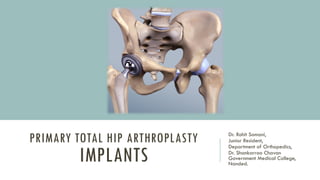
- 1. PRIMARY TOTAL HIP ARTHROPLASTY IMPLANTS Dr. Rohit Somani, Junior Resident, Department of Orthopedics, Dr. Shankarrao Chavan Government Medical College, Nanded.
- 2. HISTORY OF EVOLUTION OF THR •In 1912, Sir Robert Jones used Gold Foil as an inter positional layer, other materials used were muscle, fascia, skin, oil, rubber, celluloid, pig bladder. •In 1923, SMITH-PETERSON introduced the concept of mould arthroplasty •In 1933, PYREX GLASS was chosen as the material for the first mould.. •In 1937, Venable and Stuck developed VITTALIUM (an alloy of Cobalt 65%, Chromium 30%, Molybdnium 5%). In 1950, JUDET and BROTHERS used acrylic femoral head prosthesis made of methyl methacrylate.
- 3. •In 1952 AUSTIN MOORE and FRED THOMPSON independently conceived the idea of fixing endoprosthesis. •The 1950, WRIST, RING, Mc. KEE-FARRER and others designed the metal on metal total hip arthroplasty but did not prove satisfactory because friction and metal wear •Delbet – 1st reported hemiarthoplasty. •Giliberty and Bateman- prototype of current bipolar.
- 4. FATHER OF MODERN TOTAL HIP ARTHROPLASTY SIR JOHN CHARNLEY • Pioneering work in all aspect of THA, including the concept of low frictional torque arthroplasty, surgical alteration of hip biomechanics, lubrication, materials, design and clear air operating room environment. • LFA – low friction arthroplasty consisted of a metal femoral stem which had a small head (22.225mm) to reduce the wear on the bearing surface, a polyethylene acetabular component and acrylic bone cement along with a trochanteric osteotomy. • To overcome the failures of the Teflon cups for acetabular component, he used a high density polyethylene (HDPE), which was later replaced by (Ultra high molecular weight polyethylene)UHMWPE.
- 5. LEVER ARMS OF THE HIP JOINT Whenever abductor lever arm is increased, it reduces forces on the hip joint. This lowers the friction and frictional torque and hence lessens the chance of wear and loosening of implants
- 6. TRIBOLOGY? • Science of interactive surfaces in relative motion – fixed acetabulum and moving femoral head. • It is a study of - friction - Lubrication - Wear
- 7. WHAT IS WEAR? •It is defined as the loss of material from surfaces as a result of motion between those surfaces. •Material is in the form of particulate debris. • THR – Adhseive wear • TKR – Abrasive wear & fatigue wear •Wear rate lesser in cemented compared to uncemented. FAILURE WEAR DEBRIS OSTEOLYSIS LOOSENING
- 8. Step 1: Wear and Osteolysis • Motion between articulating surfaces •Unintended impingement or motion •Leads to formation of wear particles Step 2: Macrophage activated osteoclastogenesis and osteolysis Macrophage activation and recruitment Osteolysis by cytokines - TNF – alpha, TGF – beta - oxide radicals, hydrogen peroxide - acid phosphatase, prostaglandins - Interleukins ( IL – 1, IL – 6 ) Increase RANK and RANKL activation RANKL mediated bone resorption
- 9. Step 3: Prosthesis Micro-motion •Osteolysis surrounding the prosthesis leads to micromotion •Increase particle wear and further prosthesis loosening
- 10. NEW UNIQUE DISEASE CREATED BY HUMANS – POLY PARTICLES & OSTEOLYSIS IMMEDIATE POST OP 17 YEAR FOLLOW UP
- 11. STRESS TRANSFER TO BONE •A major concern with THR is that adaptive bone remodeling arising from stress shielding compromises implant support, produces loosening, and predisposes to fracture of the femur or the implant itself. •Cementless stems generally produce strains in the bone that are more physiological than the strains caused by fully cemented stems •Increasing the modulus of elasticity, the stem length, and the cross- sectional area of the stem increases the stress in the stem, but decreases the stress in the cement and proximal third of the femur
- 13. APPROACHES TO REDUCE WEAR AND OSTEOLYSIS •Material combinations • Cross linked polyethylene • Ceramic on ceramic • Metal on metal •Component Geometry (diameter and clearance) •Performance parameters to consider to reduce osteolysis • Wear volume • Particle shape and size • Chemical and biological activity of the debris
- 14. MATERIALS IN THR • Should be biocompatible – should evoke no more than a tolerable host reaction at local, systemic and remote side effects, consistent with the intended function of the device. • It should also evoke responses such as adhesion and ingrowth and should be able to tolerate cyclical physical loads consistently. • Youngs modulus = Stress/Strain (Stress – force per unit area, Strain – change in length from the original length) • Approximate youngs modulus – 2(PMMA): 20 (bone): 100 (Titanium): 200 (Stainless Steel & Cobalt alloys)
- 15. 1. COBALT BASED ALLOYS • contain chromium, molybdenum, carbon and other elements like nickel, silicon and iron. • Primarily used in total joint replacements because of high strength and resistance to corrosion. • High strength, High Hardness (resistance to surface deformation) • Used in making bearing surfaces and some cemented stems.
- 16. 2. TITANIUM AND TITANIUM BASED ALLOYS • High strength and fatigue resistant •Resistant to corrosion •Has an oxide surface which is inert and helps in reforming after damage. •Its low modulus of elasticity makes it favourable as it helps in transferring the load to the bone and more so in uncemented implants • Used in: Cementless Femoral stems, Acetabular shells •Cannot be used in femoral heads due to wear (softer)
- 17. 3. STAINLESS STEEL • Most common steel used in implants is the 316 steel • inferior to both cobalt and titanium alloys when it comes to corrosion resistance, biocompatibility and fatigue life •Used in femoral components due to high strength, low cost and easy workability
- 18. 4. ZIRCONIUM AND TANTALUM ALLOYS • Zirconium is similar to titanium in some aspects. • being tested for making femoral heads. • Tantalum is used a bone ingrowth substrate for porous coated surfaces and has excellent biocompatibility • used in filling up bone defects in revision scenarios.
- 19. COMPONENTS OF THA Acetabular component - consists of two components Cup - usually made of titanium Liner - can be plastic, metal or ceramic Femoral components - consists of two components Head - metal, ceramic Neck & stem - metal
- 20. IMPLANT SELECTION IN THA Bearing options Metal on Poly Ceramic on Poly Ceramic on ceramic Dual mobility systems Constrained liners Fixation strategies Cemented systems Uncemented systems Hybrid options
- 21. FEMORAL COMPONENTS • The primary function of the femoral component is the replacement of the femoral head and neck after resection of the arthritic or necrotic segment. • The ideal femoral reconstruction reproduces the normal center of rotation of femoral head, which can be determined by -Vertical height (vertical offset) -Medial head stem offset ( horizontal offset) -Version of the femoral neck(anterior offset)
- 22. • Vertical offset- LT to center of the femoral head. Restoration of this distance is essential in correction of leg length. • Medial head stem offset- distance from the center of the femoral head to a line through the axis of the distal part of stem. Medial offset if inadequate, shortens the moment arm – limp, increase, bony impingement and dislocation. Excessive medial offset –increase stress on stem and cement which causes stress fracture or loosening. • Version of the femoral neck : important in achieving stability of the prosthetic joint. The normal femur has 10-15 degree of anteversion.
- 23. METHODS BY WHICH THE HORIZONTAL OFFSET CAN BE CHANGED • Increasing the neck length • Decreasing the neck shaft angle • High offset implant (medialize the neck and concomitantly increase its length) •Trochanteric osteotomy •Acetabular component
- 24. HEAD SIZE • Range of head sizes – 22, 26, 28, 32, 34 mm. • Large size femoral heads improve the range of motion and the fluid film lubrication would reduce the wear rates. • smaller size of head is associated with increased rate of dislocation. •AOM (Arc of motion) directly proportional to Femoral head:neck ratio
- 25. • For a given neck diameter, the use of a larger femoral head increases the head- neck ratio and the range of motion before the neck impinges on the rim of the socket will be greater. •When this impingement does occur, the femoral head is levered out of the socket. •The “jump distance” is the distance the head must travel to escape the rim of the socket and is generally approximated to be half the diameter of the head.
- 26. • The size of the femoral head, the ratio of head and neck diameters, and the shape of the neck of the femoral component have a substantial effect on the range of motion of the hip, the degree of impingement between the neck and rim of the socket, and the stability of the articulation. •Neck geometry and arc of motion •Trapezoidal and oval neck increases the arc of motion •Circular neck decreases AOM •The ideal configuration of the prosthetic head and neck segment includes a trapezoidal neck and a larger diameter head without a skirt
- 27. DORR CLASSIFICATION OF PROXIMAL FEMURS
- 28. CEMENTED FEMORAL STEM 1. Cobalt chromium alloy – high Elasticity, Reduce stress 2. Cross section – broad medial border, broader lateral border 3. Sharp edges avoided – Stress riser 4. Stem should cover 80 % of femoral canal. Proximal cement mantle – 4 mm Distal cement mantle – 2 mm 5. Smooth polished surface – less debris, less loosening, less wear tear 6. Stem length – 120 to 130 mm Larger stem – varus malposition and anterior cortex perforation
- 31. CEMENTLESS FEMORAL STEM • Designed to ensure intimate contact between the implant and the bone which reduced the motion between the two. •Based on the principle-bone ingrowth from the viable host bone into porous metal surfaces of implant. •Indications for cementless components 1. primarily active young patients 2. revisions of failed cemented components. •The close contact between the implant and the host bone is the key. Ideal gap of about 50 µm can be bridged. More than 100 µm decreases the chances of bony incorporation.
- 32. • Coated by surfaces that promote bone formation •Surface Coating – Proximal, Extensive, Fully coated • Surface treatment with Sintered Beads, Titanium mesh with or without HA coating. • Material of stem – Titanium , Chromium Cobalt alloy • Shapes – Cylindrical, Tapered, Anatomical 1. Cylindrical Stems – symmetrical in cross section, allow contact in proximal diaphysis 2. Tapered stems – wedge shaped with widening in the proximal half, improved contact with metaphysis and therefore rotational stability 3. Anatomic stems – Proximal posterior bow and distal anterior bow
- 38. NON POROUS COATED FEMORAL STEMS •Non-porous femoral implants have surface roughening that provide a macrointerlock with bone •No capacity for bone ingrowth but provides lasting implant stability •With the concerns about fatigue strength, ion release and adverse femoral remodeling, these non porous stems came into use over porous stems
- 39. •Smaller stems have also come in because metaphyseal fit and ingrowth can allow rotational and axial stability without the need for diaphyseal support. • This allow preserves proximal bone stock, especially in young patients who may need revision surgery
- 40. WHICH STEM TO CHOOSE? Young active patient more demands DORR TYPE A & B NON CEMENTED STEM PROXIMAL COATED METAPHYSEAL ENGAGING STEMS (TAPERED) Old patient with <10 years life expectancy and less demands DORR TYPE B & C CEMENTED STEM SMOOTH FINISH METAPHYSEAL ENGAGING
- 41. ACETABULAR COMPONENT Optimum position for the prosthetic socket which should be inclined 45⁰ or less to maximize stability of the joint (normal 55⁰). Types : 1. Cemented acetabular components. 2. Cementless acetabular components. 3. Custom made acetabular components
- 42. CEMENTED ACETABULAR COMPONENT • Original sockets- •thick walled polyethylene cups. Vertical and horizontal grooves on external surface to increase stability within the cement mantle •wire markers were embedded in plastic to allow better assessment of position on postoperative roentgenograms. • Recent designs- •have a textured metal back which improves adhesion at the prosthesis cemented interface. A flange at the rim improves pressurization of the cement. •used in elderly patients, tumour reconstruction and the circumstances with less chances of bony ingrowth as in revision THR.
- 43. NON CEMENTED ACETABULAR COMPONENTS •Most cementless acetabular components are porous coated over their entire circumference for bone ingrowth •Fixation of the porous shell with transacetabular screws •Pegs and spikes driven into prepared recesses in the bone provide some rotational stability but less than that obtained with screws.
- 44. ZTT socket Hemispherical , porous coated cup designed with dome screw holes and transacetabular screws for stability. Six peripheral screw holes provide choice of screw locations for additional stability and also lock in the polyethylene insert.
- 45. LINER •Liners have been proven to be another zone of failures in the cmeentless cups •Focus being on the • Material • Locking mechanism to the acetabular shell • With an improvement in locking mechanisms, the earlier problem of “Backside Wear” has lessened.
- 46. BEARING OPTIONS 1. Metal on Poly 2. Ceramic on Polyethylene 3. Metal on Metal 4. Ceramic on Ceramic
- 47. POLYETHYLENE • UHMWPE has been the bearing material of choice in THA for over 50 years now. •PTFE (polytetrafluoroethylene) was the initial choice by charnley but it failed miserably. • The polyethylene liner must be fastened securely to the metal shell. •Current mechanisms include plastic flanges and metal wire rings that lock behind elevations or ridges in the metal shell, and peripherally placed screws • in vivo dissociation of polyethylene liners from their metal backings has been reported micromotion between the nonarticulating side of the liner and the interior of the shell may be a source of polyethylene debris generation, or “backside wear.”
- 48. GOLD STANDARD •The bearing to which all others shoulder be compared – Chrome cobalt on UHMWPE sterilized with 2.5 to 4 mrads in air •This has an approx. linear wear rate of 0.01 to 0.02 mm/year
- 50. CROSS LINKING •Chemical nature of UHMWPE consists of long chain of polyethylene molecules in parallel orientation •Exposure of these to gamma radiations leads to free radical formations which help in formation of cross links between adjacent polyethylene chains •This cross linking highly improves the wear resistance. •Degree of cross linking depends on • Type of irradiation • Amount of irradiation • Duration • Atmosphere in which the irradiation is carried out in.
- 51. XPLE reduces wear by 85% compared to conventional poly XPLE wear particles are small and are more reactive Models predicts and 4 fold reduction in osteolytic potentital compared to conventional polyethylene Concerns increased wear when XPLE is used in active patients with Larger head Highly cross linked poly – newer development wherein high doses of radiation more than 5 mrad are given Improved mechanical wear properties and also decreases the oxidation of polyethylene which was seen in the previous generations
- 53. METAL ON METAL In 1988, second generation MOM bearings were introduced These are carbide containing forged Co-Cr-Mo alloy Better implant design with optimal clearance resulted in low wear rate and longer life and were used in younger patients Recent studies show a perivascular inflammation with prominent lymphocytic cuff – under scrutiny Increase levels of Co and chromium in blood and urine which are not BIOINERT Not in use anymore
- 54. ALVAL LESION (ASEPTIC LYMPHOCYTIC DOMINATED VASCULTIS ASSOCIATED LESION) Hypersensitivity type IV Groin pain Green gray coloured fluid Looking like an abscess/pseudotumour
- 55. CERAMIC •FATHER OF CERAMIC – BUTIN 1970 •FIRST AND SECOND GEN OF CERAMICS •Started in Europe and japan •Monolithic acetabular component, fabricated from alumina ceramics (AI203) •Modular acetabular component with metal backing with biological coating to improved the fixation later on •Failure due to oFixation was the biggest problem initially oMigration and tilting of the component oEdge loading, accelerated wear and impingement oFracture of the acetabular component
- 56. MEDICAL GRADE CERAMIC Composed of pure crystals of aluminum or zirconium oxides •Most chemically inert •Biologically inert •Stiff •Strong •Hard •Only substance harder than aluminum oxide is diamond
- 57. CERAMIC-ON-CERAMIC BEARING MECHANICAL LAW: Harder surfaces coupled together reduce the wear of the coupling surfaces and produce very low rates of wear particles. CERAMIC MATERIAL: Hardness which it gives can be polished to much lower surface roughness with wear resistance and scratch resistance
- 58. HYDROPHIILIC PROPERTY •Improved wettability of ceramics contributes to lower friction than CoCr when articulated against UHMWPE under physiological loading and lubrication conditions •It ensures that the synovial fluid film is uniformly distributed over the whole bearing surface areas
- 59. SUBOPTIMAL POSITIONING OF THE CUP •Hardness and wear are sensitive to design, manufacturing and implant variables •Rapid wear has been also observed, generally associated with sub optimal positioning of the implants •Edge loading, increased wear, fractures etc.
- 60. DISADVANTAGE •Cannot deform under stress •When stresses acting on medical ceramic components exceed a certain limit, the ceramic material bursts. •Revision is very difficult in these cases •Modern third generation ceramics are better and will not burst out but will chip off during assembling with the metallic backup
- 61. •The feared fracture of the ceramic components mainly the ball has notably disappeared off late due to two main technological developments 1. Introduction of individual testing of every ceramic component before it is shipped and sold to the surgeon (1993) 2. Hot isostatic pressing (HIP): So alumina ceramics are produced in very dense fine grain alumina with very limited grain boundaries and inclusions
- 62. POSSIBLE CONCERNS WITH CERAMIC HIPS • Squeaking noise, clicking noise • Stripe wear •Studies have demonstrated that these noises from ceramic total hips are associated with faulty position of the ceramic cup(Walter 2007)
- 63. DELTA CERAMICS (BIOLOX DELTA) •Zirconia toughened alumina (ZTA) ceramic •Nano sized •75% alumina and rest is zirconium, yttrium and chrome •Superior strength and wear •Helps to limit crack propogration
- 64. CERAMIC-ON-POLY Ceramic heads have better wear characteristics compared to metal heads Decrease in osteolysis Wear rate is 0.25-0.75% of metal on poly articultaions DISADVANTAGE Highly taper tolerance sensitive – cannot revise with existing taper Risk of ceramic head fracture IT IS THE INTERNATIONAL WORKHORSE IN THA
- 67. OXINIUM (OXIDIZED ZIRCONIUM) •It is a zirconium metal alloy that is placed through an oxidation process to yield an implant with a zirconia ceramic surface. •Weighs 20% lighter •Useful in young active patients
- 68. DUAL MOBILITY CUPS •Head articulates within a retentive polyethylene •Poly is free to move in a metal shell in a NON RETENTIVE WAY •Increased stability •INDICATIONS 1. Done in patients with weak or poor soft tissues 2. Neuromuscular issues 3. Complex primary stituations like ankylosed hips 4. Revision scenario (Dislocations)
- 69. CONSTRAINED ACETABULAR LINER Mechanism: lock the prosthetic femoral head into the polyethylene liner Indications Insufficient soft tissues Deficient hip abduction Neuromuscular disease Hip with recurrent dislocations despite well positioned implants Longevity is around 7 or 8 years, used as final salvage.
- 70. CONCLUSION •Avoid metal heads more than 32 mm size to rule out the risk of trunionosis •Ceramic on highly cross linked poly is the most common bearing used world wide with oxinium being preferred at some centers •Ceramic on ceramic reserved for younger patients •Head size more than 36 mm is not desirable as it increase the risk of trunion wear •28,32, 36 are commonly used •Cemented in older patients with less life expectancy •Uncemented in younger population
- 71. THANK YOU