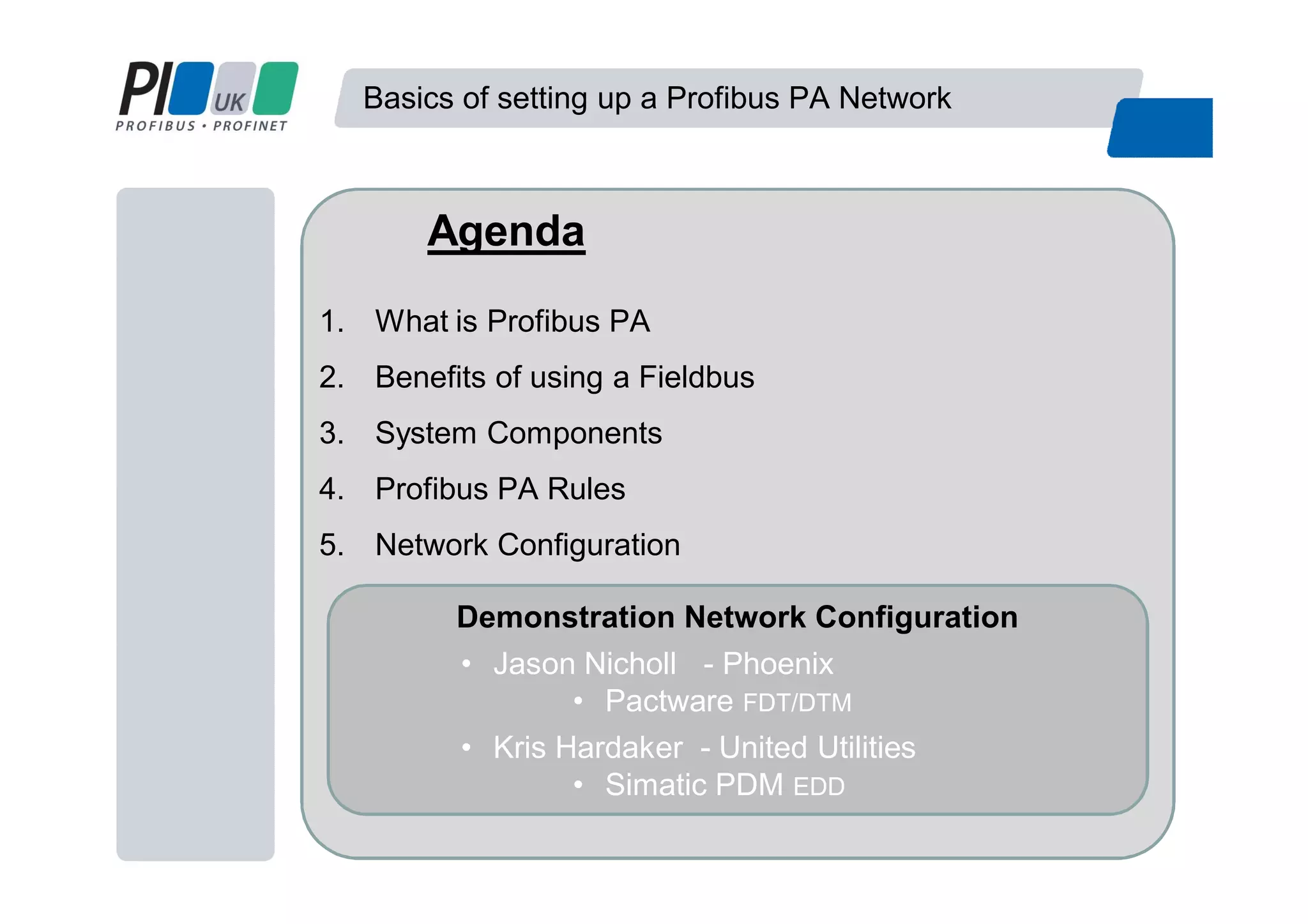
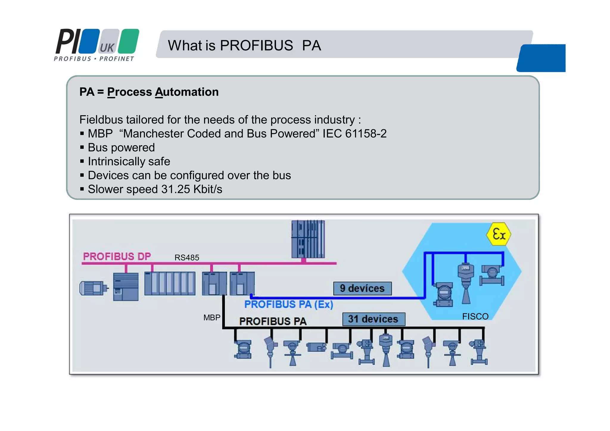
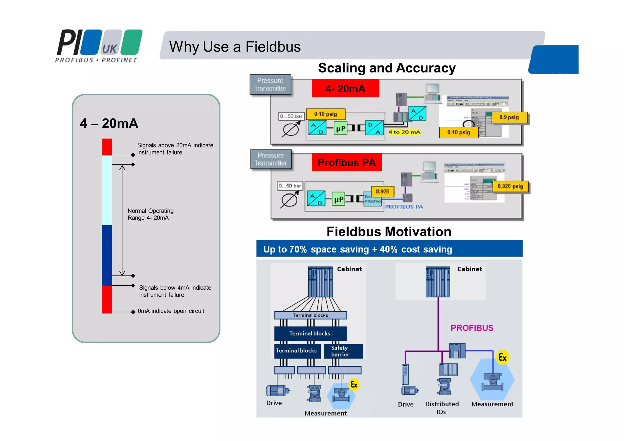
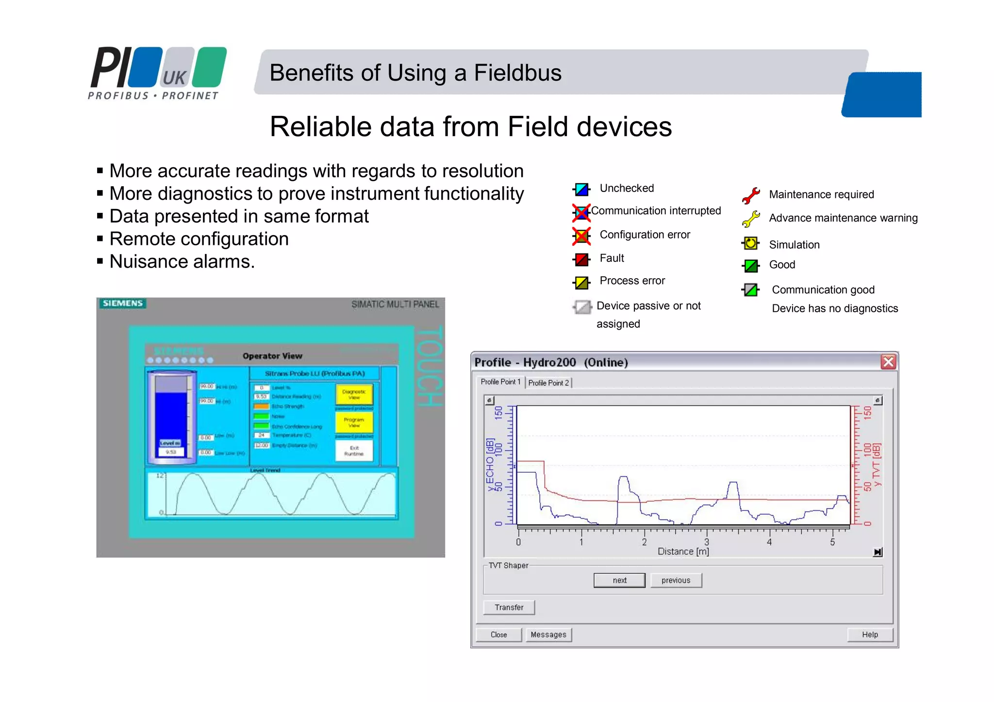
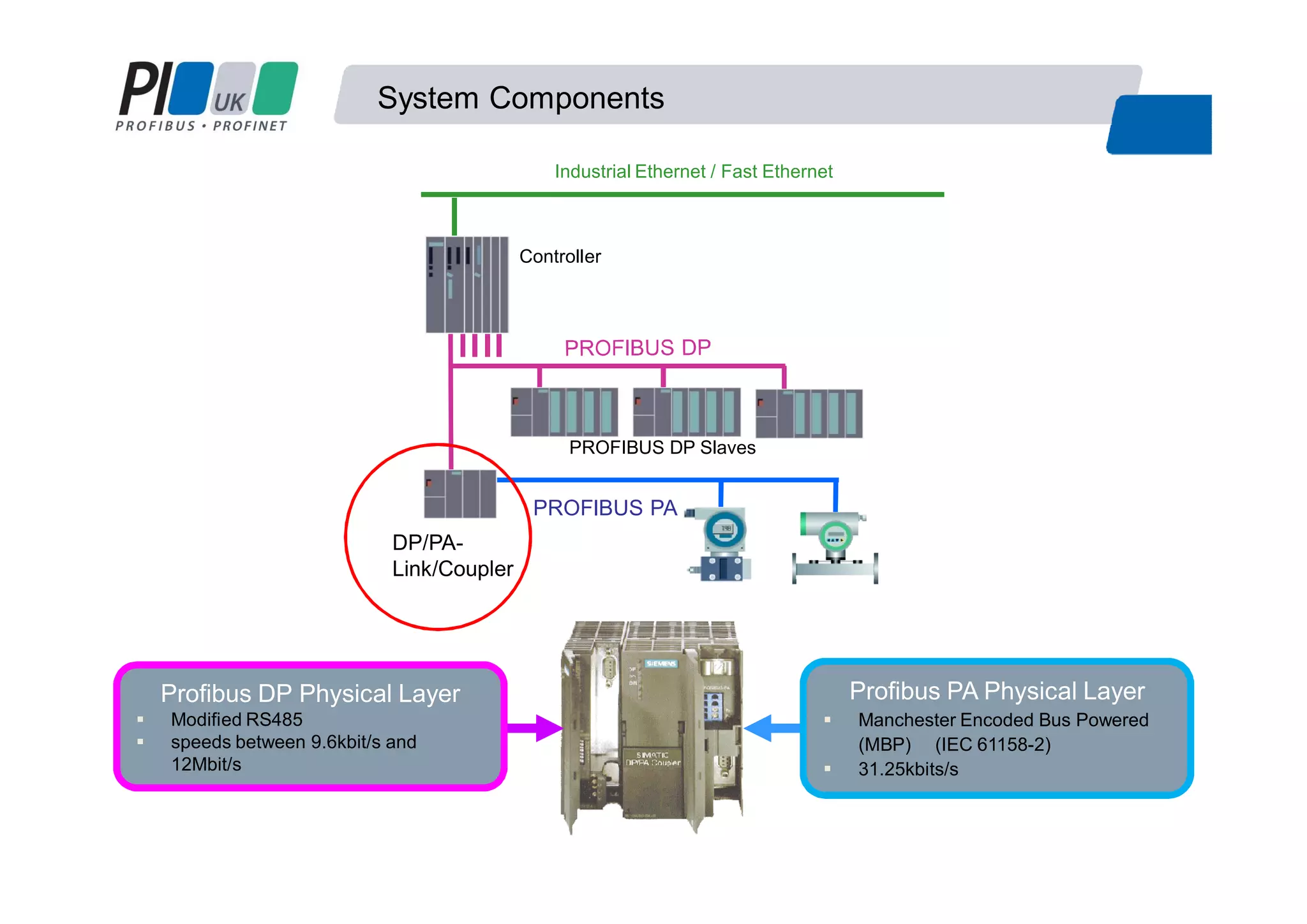
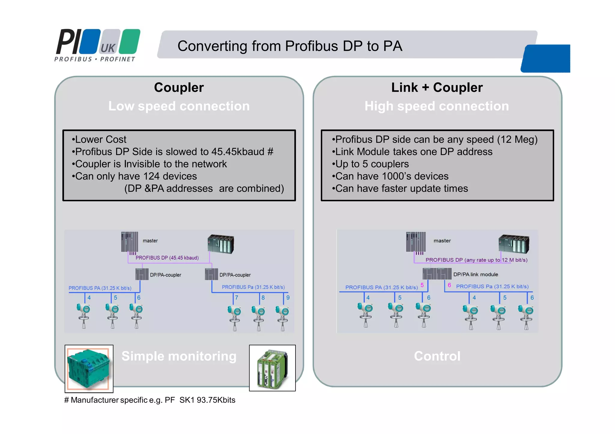
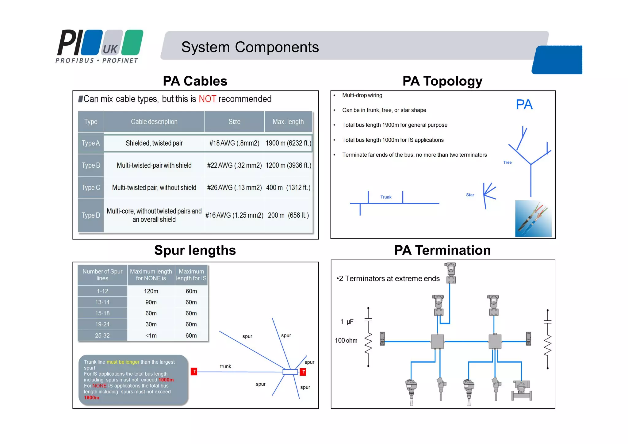
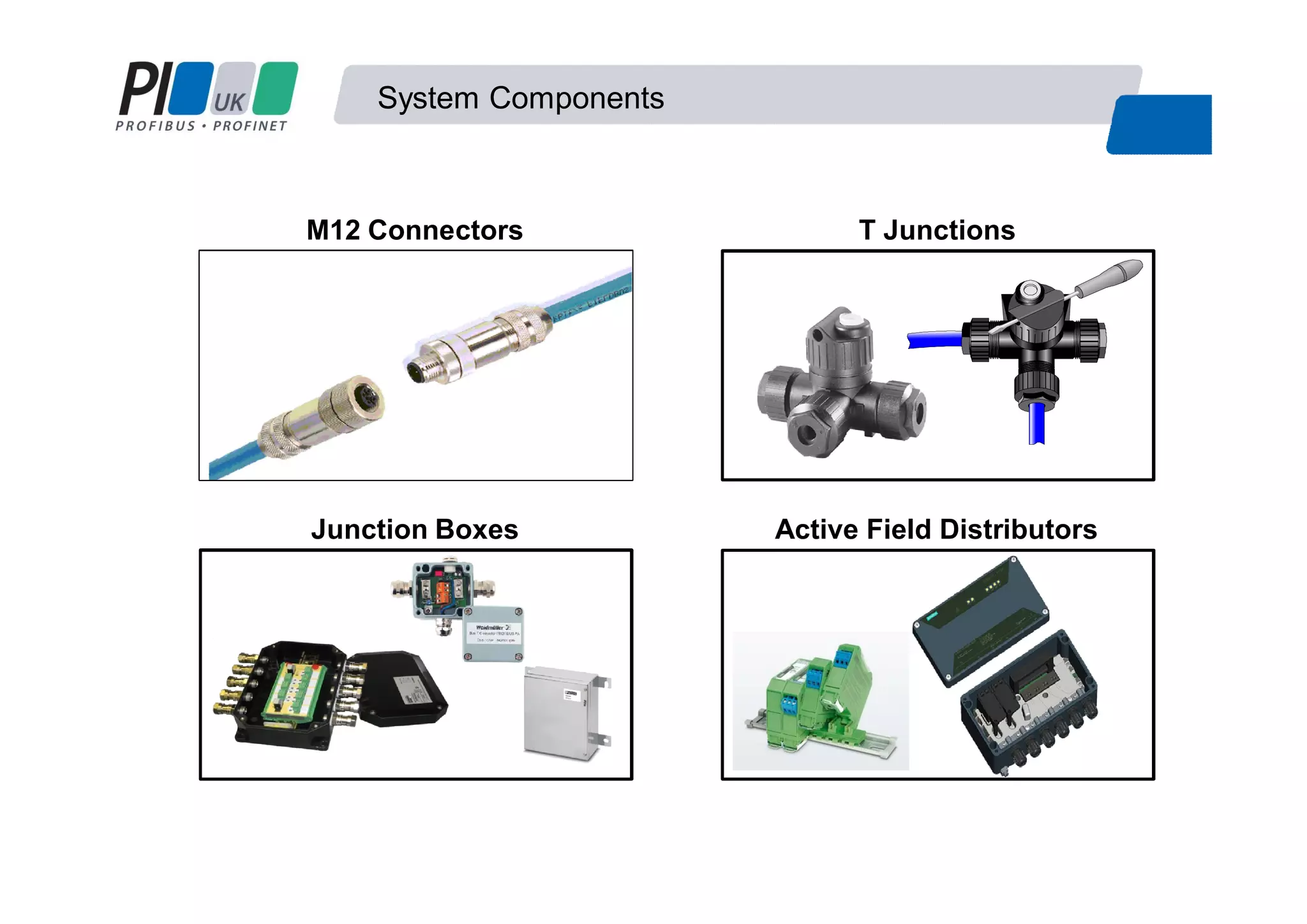
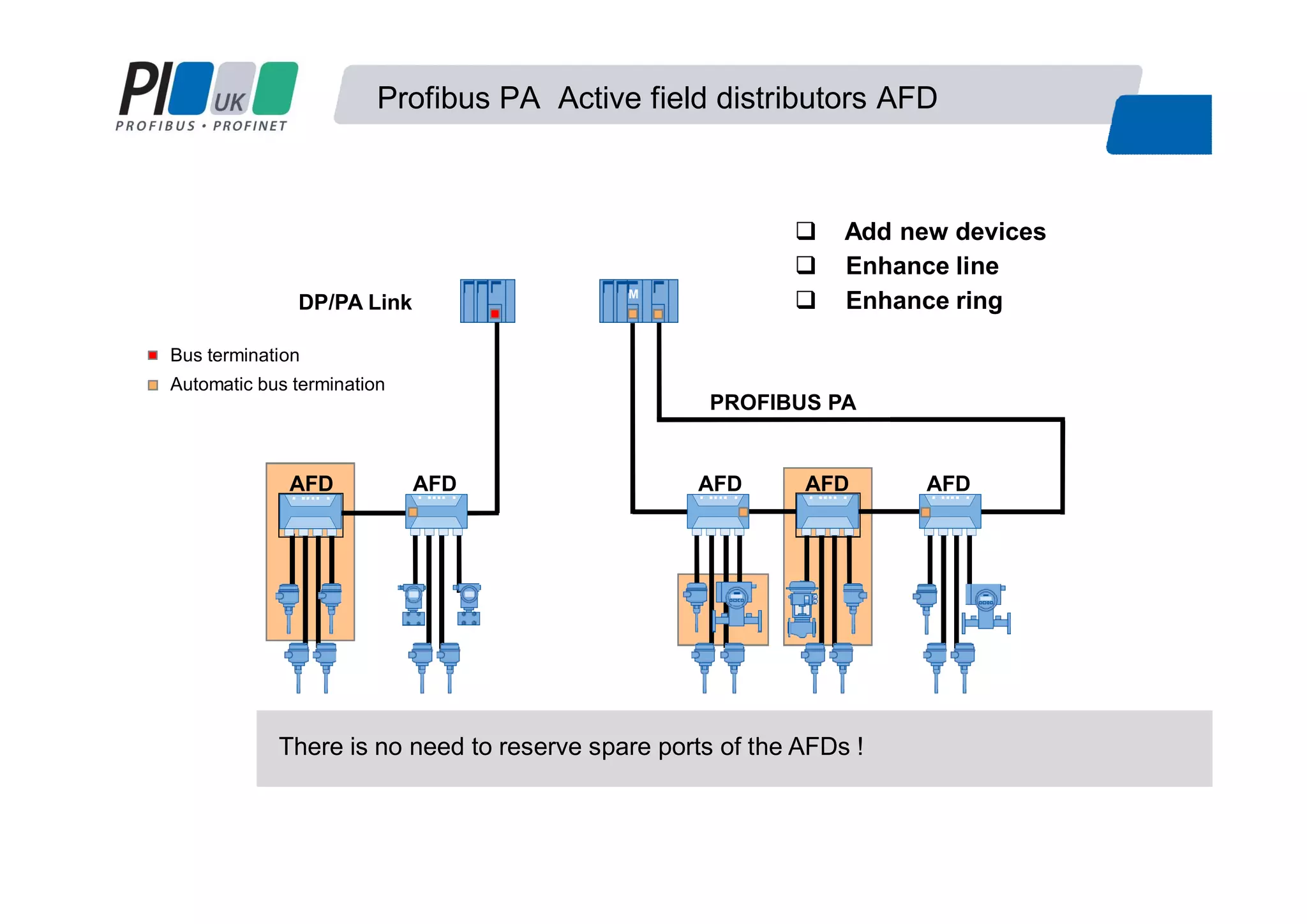
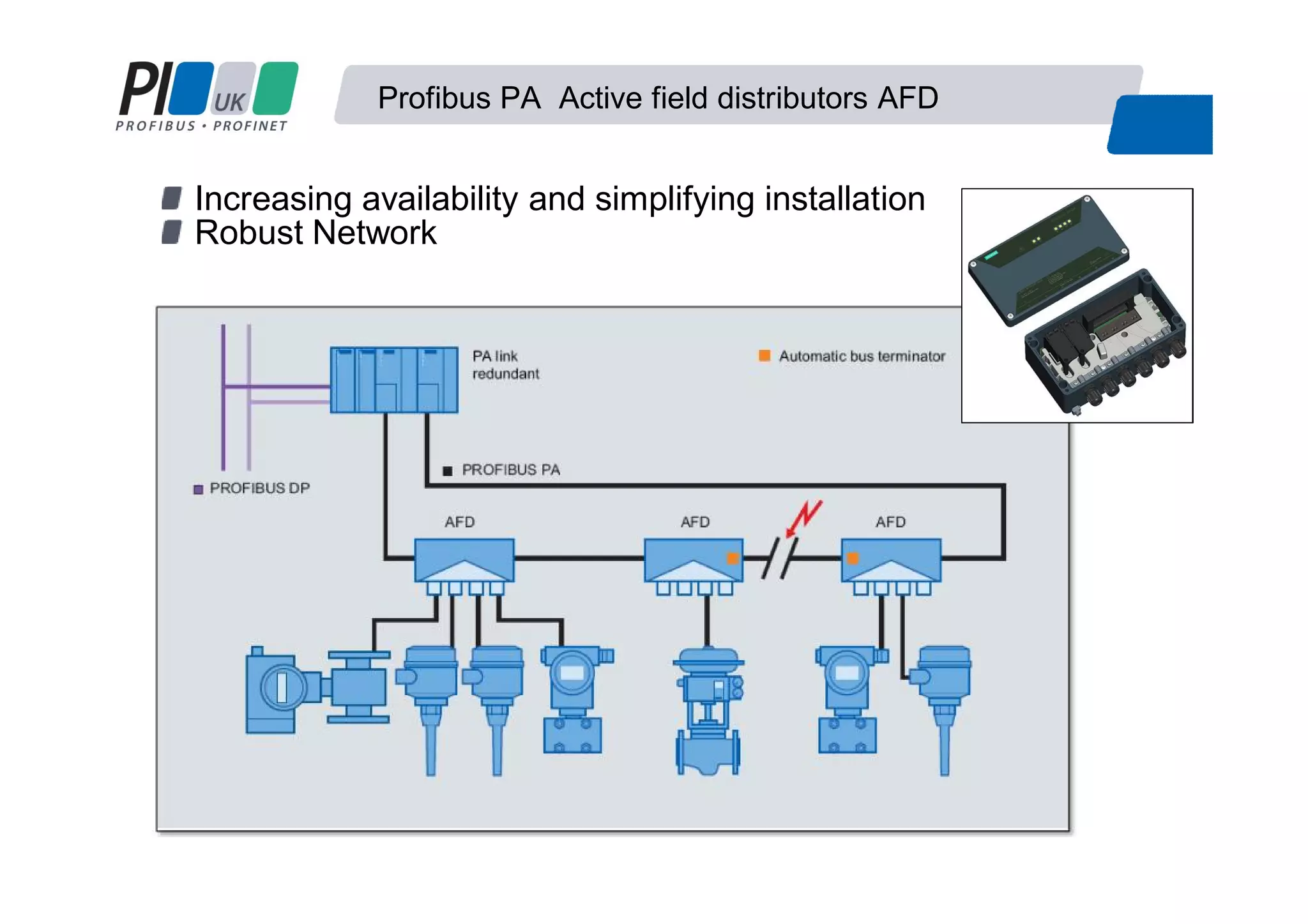
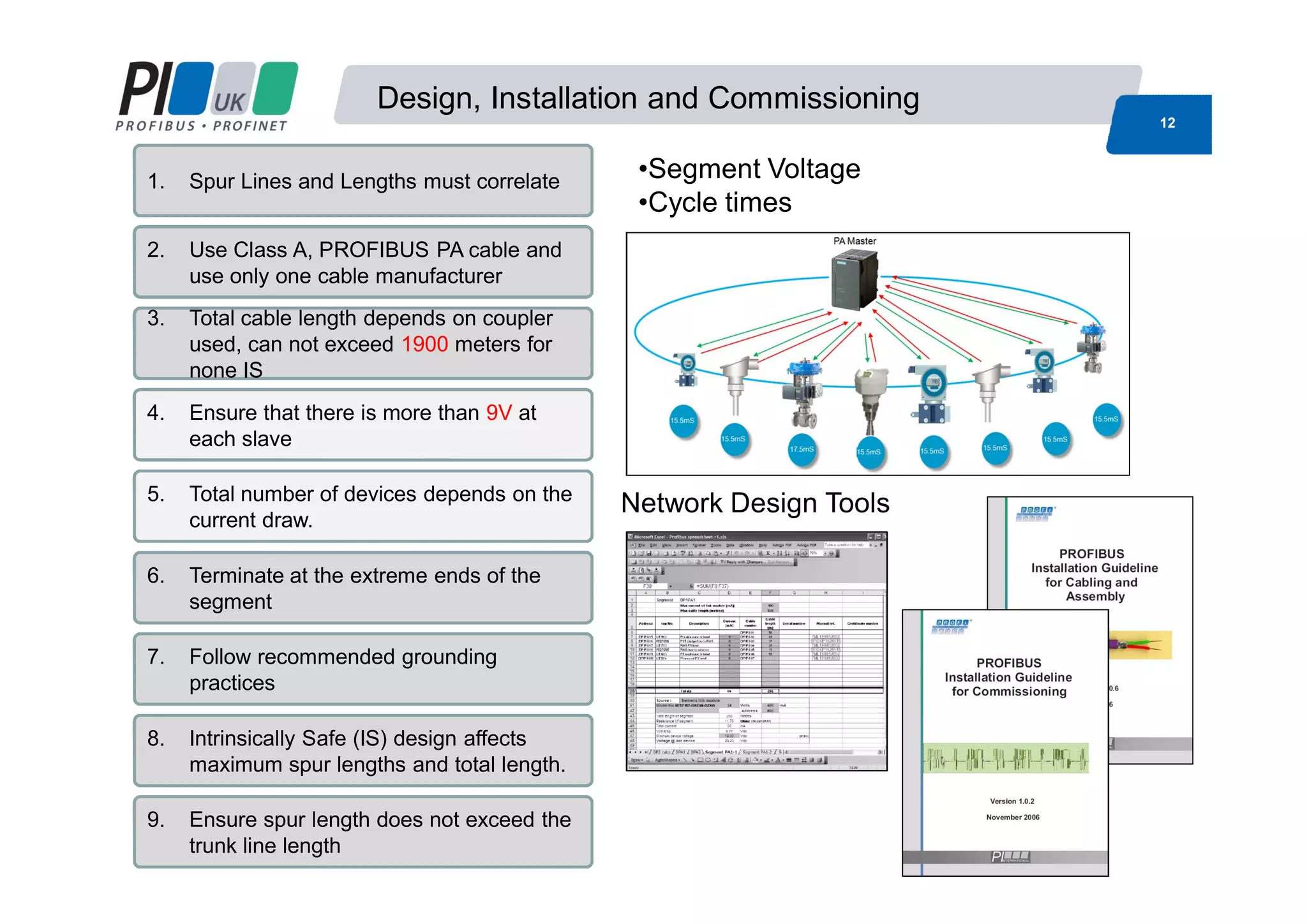
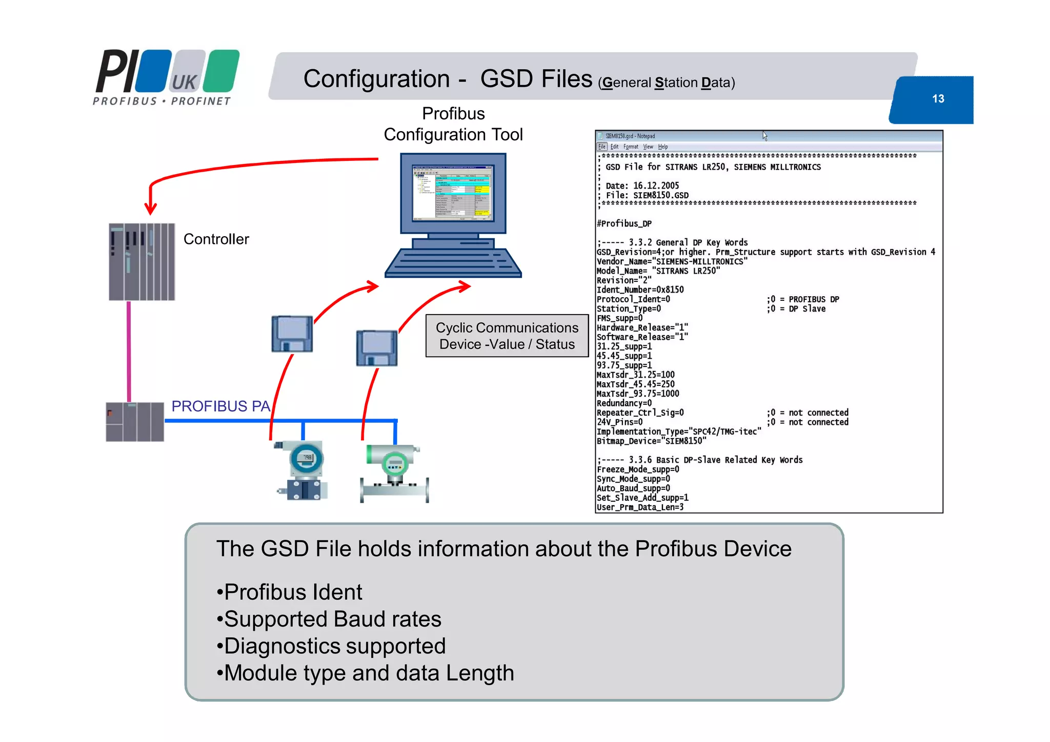
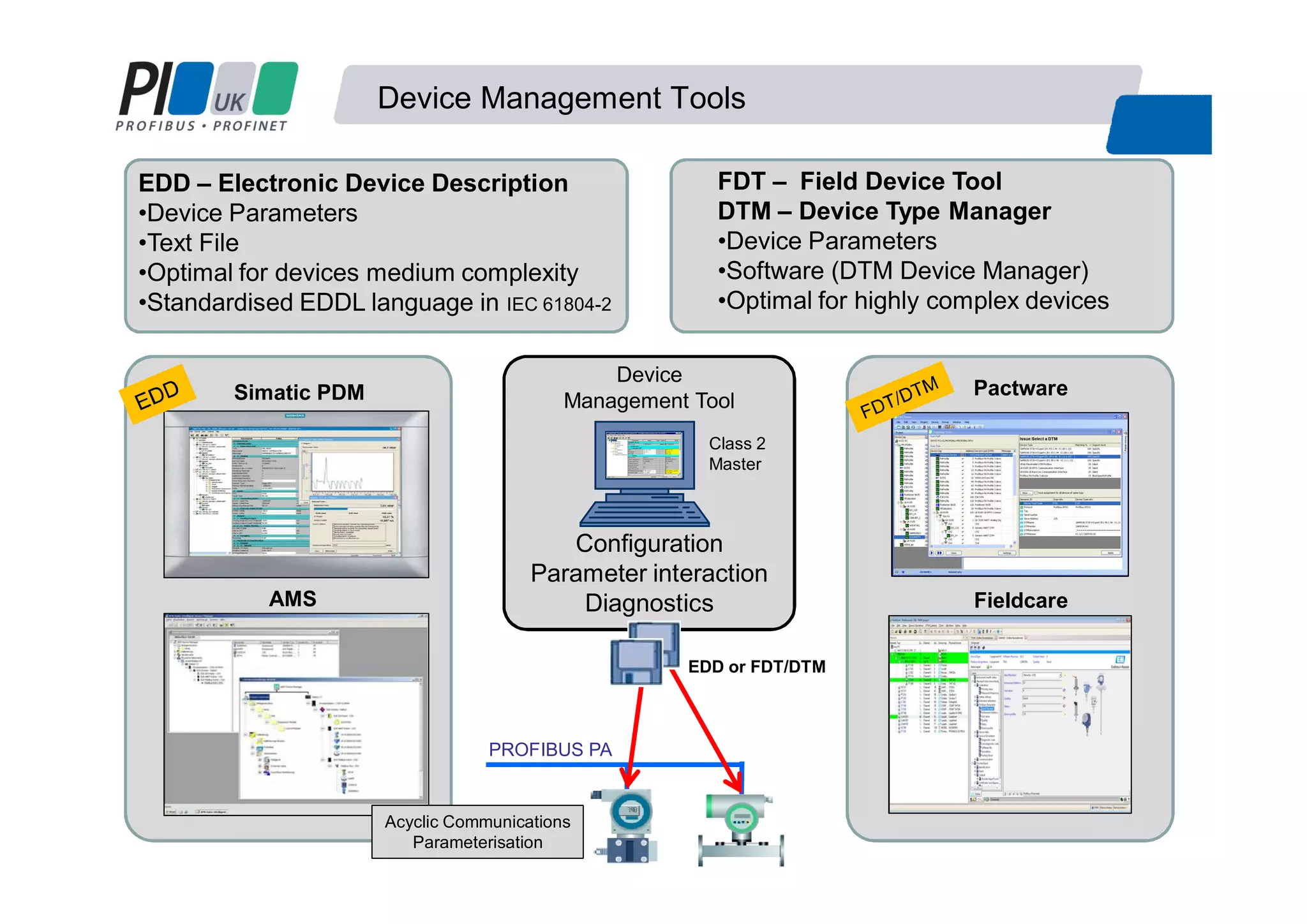
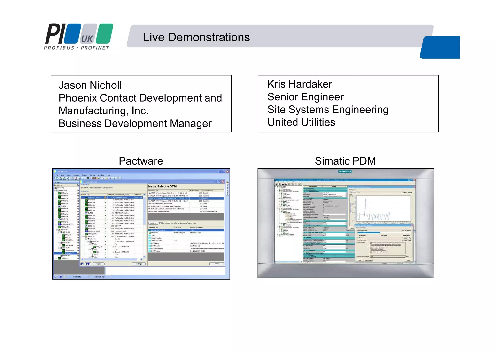
W05 Basics of setting up
PROFIBUS-PA networks
Martin Ruck
Siemens
Jason Nicholl
Phoenix
Kris Hardaker
United Utilities
Basics of setting up a Profibus PA Network
1. What is Profibus PA
2. Benefits of using a Fieldbus
3. System Components
4. Profibus PA Rules
5. Network Configuration
Agenda
Demonstration Network Configuration
• Jason Nicholl - Phoenix
• Pactware FDT/DTM
• Kris Hardaker - United Utilities
• Simatic PDM EDD
PA =PA = PProcessrocess AAutomationutomation
Fieldbus tailored for the needs of the process industry :
MBP “Manchester Coded and Bus Powered” IEC 61158-2
Bus powered
Intrinsically safe
Devices can be configured over the bus
Slower speed 31.25 Kbit/s
What is PROFIBUS PA
FISCO
RS485
MBP
Why Use a Fieldbus
Normal Operating
Range 4- 20mA
Signals below 4mA indicate
instrument failure
0mA indicate open circuit
Signals above 20mA indicate
instrument failure
4 – 20mA
Scaling and Accuracy
Fieldbus Motivation
Profibus PA
4- 20mA
Benefits of Using a Fieldbus
Reliable data from Field devices
More accurate readings with regards to resolution
More diagnostics to prove instrument functionality
Data presented in same format
Remote configuration
Nuisance alarms. Good
Unchecked
Configuration error
Fault
Maintenance required
Advance maintenance warning
Process error
Communication interrupted
Simulation
Communication good
Device has no diagnosticsDevice passive or not
assigned
System Components
Controller
PROFIBUS DP Slaves
PROFIBUS PA
DP/PA-
Link/Coupler
Industrial Ethernet / Fast Ethernet
Profibus DP Physical Layer
Modified RS485
speeds between 9.6kbit/s and
12Mbit/s
Profibus PA Physical Layer
Manchester Encoded Bus Powered
(MBP) (IEC 61158-2)
31.25kbits/s
Converting from Profibus DP to PA
Coupler Link + Coupler
Low speed connection High speed connection
# Manufacturer specific e.g. PF SK1 93.75Kbits
•Lower Cost
•Profibus DP Side is slowed to 45.45kbaud #
•Coupler is Invisible to the network
•Can only have 124 devices
(DP &PA addresses are combined)
•Profibus DP side can be any speed (12 Meg)
•Link Module takes one DP address
•Up to 5 couplers
•Can have 1000’s devices
•Can have faster update times
Simple monitoring Control
4 5 6 7 8 9 4 5 6 4 5 6
5 6
System Components
PA TopologyPA Cables
Spur lengths PA Termination
•2 Terminators at extreme ends
System Components
M12 Connectors T Junctions
Junction Boxes Active Field Distributors
Add new devices
PROFIBUS PA
Automatic bus termination
AFD
Bus termination
Enhance line
Enhance ringM
There is no need to reserve spare ports of the AFDs !
AFDAFDAFD AFD
DP/PA Link
Profibus PA Active field distributors AFD
Increasing availability and simplifying installation
Robust Network
Design, Installation and Commissioning
12
1. Spur Lines and Lengths must correlate
2. Use Class A, PROFIBUS PA cable and
use only one cable manufacturer
3. Total cable length depends on coupler
used, can not exceed 1900 meters for
none IS
4. Ensure that there is more than 9V at
each slave
5. Total number of devices depends on the
current draw.
6. Terminate at the extreme ends of the
segment
7. Follow recommended grounding
practices
8. Intrinsically Safe (IS) design affects
maximum spur lengths and total length.
9. Ensure spur length does not exceed the
trunk line length
Network Design Tools
•Segment Voltage
•Cycle times
Configuration - GSD Files (General Station Data)
13
Controller
PROFIBUS PA
Profibus
Configuration Tool
The GSD File holds information about the Profibus Device
•Profibus Ident
•Supported Baud rates
•Diagnostics supported
•Module type and data Length
Cyclic Communications
Device -Value / Status
Device Management Tools
Simatic PDM
AMS
Pactware
Fieldcare
Configuration
Parameter interaction
Diagnostics
Device
Management Tool
Class 2
Master
PROFIBUS PA
EDD or FDT/DTM
EDD – Electronic Device Description
•Device Parameters
•Text File
•Optimal for devices medium complexity
•Standardised EDDL language in IEC 61804-2
FDT – Field Device Tool
DTM – Device Type Manager
•Device Parameters
•Software (DTM Device Manager)
•Optimal for highly complex devices
Acyclic Communications
Parameterisation
Live Demonstrations
Pactware Simatic PDM
Kris Hardaker
Senior Engineer
Site Systems Engineering
United Utilities
Jason Nicholl
Phoenix Contact Development and
Manufacturing, Inc.
Business Development Manager
Contact
Basics of setting up a Profibus PA Network
Jason Nicholl
Business Development Manager
Phoenix Contact Development and Manufacturing, Inc
I/O and Networks Business Unit, Americas
Tel: 1-800-888-7388 x3720
Email: JNicholl@phoenixcon.com
Kris Hardaker
Senior Engineer
Site Systems Engineering
United Utilities
T: 01925 731037 (internal 31037)
Email: Kris.Hardaker@uuplc.co.uk
Martin Ruck
Product Manager
Process Instrumentation
Siemens Industry GB&I
Mobile: +44 (0) 7808 824913
Email: martin.ruck@siemens.com
Thank you for your time

W05 basics of setting up Profibus process automation networks

  • 1.
    W05 Basics ofsetting up PROFIBUS-PA networks Martin Ruck Siemens Jason Nicholl Phoenix Kris Hardaker United Utilities
  • 2.
    Basics of settingup a Profibus PA Network 1. What is Profibus PA 2. Benefits of using a Fieldbus 3. System Components 4. Profibus PA Rules 5. Network Configuration Agenda Demonstration Network Configuration • Jason Nicholl - Phoenix • Pactware FDT/DTM • Kris Hardaker - United Utilities • Simatic PDM EDD
  • 3.
    PA =PA =PProcessrocess AAutomationutomation Fieldbus tailored for the needs of the process industry : MBP “Manchester Coded and Bus Powered” IEC 61158-2 Bus powered Intrinsically safe Devices can be configured over the bus Slower speed 31.25 Kbit/s What is PROFIBUS PA FISCO RS485 MBP
  • 4.
    Why Use aFieldbus Normal Operating Range 4- 20mA Signals below 4mA indicate instrument failure 0mA indicate open circuit Signals above 20mA indicate instrument failure 4 – 20mA Scaling and Accuracy Fieldbus Motivation Profibus PA 4- 20mA
  • 5.
    Benefits of Usinga Fieldbus Reliable data from Field devices More accurate readings with regards to resolution More diagnostics to prove instrument functionality Data presented in same format Remote configuration Nuisance alarms. Good Unchecked Configuration error Fault Maintenance required Advance maintenance warning Process error Communication interrupted Simulation Communication good Device has no diagnosticsDevice passive or not assigned
  • 6.
    System Components Controller PROFIBUS DPSlaves PROFIBUS PA DP/PA- Link/Coupler Industrial Ethernet / Fast Ethernet Profibus DP Physical Layer Modified RS485 speeds between 9.6kbit/s and 12Mbit/s Profibus PA Physical Layer Manchester Encoded Bus Powered (MBP) (IEC 61158-2) 31.25kbits/s
  • 7.
    Converting from ProfibusDP to PA Coupler Link + Coupler Low speed connection High speed connection # Manufacturer specific e.g. PF SK1 93.75Kbits •Lower Cost •Profibus DP Side is slowed to 45.45kbaud # •Coupler is Invisible to the network •Can only have 124 devices (DP &PA addresses are combined) •Profibus DP side can be any speed (12 Meg) •Link Module takes one DP address •Up to 5 couplers •Can have 1000’s devices •Can have faster update times Simple monitoring Control 4 5 6 7 8 9 4 5 6 4 5 6 5 6
  • 8.
    System Components PA TopologyPACables Spur lengths PA Termination •2 Terminators at extreme ends
  • 9.
    System Components M12 ConnectorsT Junctions Junction Boxes Active Field Distributors
  • 10.
    Add new devices PROFIBUSPA Automatic bus termination AFD Bus termination Enhance line Enhance ringM There is no need to reserve spare ports of the AFDs ! AFDAFDAFD AFD DP/PA Link Profibus PA Active field distributors AFD
  • 11.
    Profibus PA Activefield distributors AFD Increasing availability and simplifying installation Robust Network
  • 12.
    Design, Installation andCommissioning 12 1. Spur Lines and Lengths must correlate 2. Use Class A, PROFIBUS PA cable and use only one cable manufacturer 3. Total cable length depends on coupler used, can not exceed 1900 meters for none IS 4. Ensure that there is more than 9V at each slave 5. Total number of devices depends on the current draw. 6. Terminate at the extreme ends of the segment 7. Follow recommended grounding practices 8. Intrinsically Safe (IS) design affects maximum spur lengths and total length. 9. Ensure spur length does not exceed the trunk line length Network Design Tools •Segment Voltage •Cycle times
  • 13.
    Configuration - GSDFiles (General Station Data) 13 Controller PROFIBUS PA Profibus Configuration Tool The GSD File holds information about the Profibus Device •Profibus Ident •Supported Baud rates •Diagnostics supported •Module type and data Length Cyclic Communications Device -Value / Status
  • 14.
    Device Management Tools SimaticPDM AMS Pactware Fieldcare Configuration Parameter interaction Diagnostics Device Management Tool Class 2 Master PROFIBUS PA EDD or FDT/DTM EDD – Electronic Device Description •Device Parameters •Text File •Optimal for devices medium complexity •Standardised EDDL language in IEC 61804-2 FDT – Field Device Tool DTM – Device Type Manager •Device Parameters •Software (DTM Device Manager) •Optimal for highly complex devices Acyclic Communications Parameterisation
  • 15.
    Live Demonstrations Pactware SimaticPDM Kris Hardaker Senior Engineer Site Systems Engineering United Utilities Jason Nicholl Phoenix Contact Development and Manufacturing, Inc. Business Development Manager
  • 16.
    Contact Basics of settingup a Profibus PA Network Jason Nicholl Business Development Manager Phoenix Contact Development and Manufacturing, Inc I/O and Networks Business Unit, Americas Tel: 1-800-888-7388 x3720 Email: JNicholl@phoenixcon.com Kris Hardaker Senior Engineer Site Systems Engineering United Utilities T: 01925 731037 (internal 31037) Email: Kris.Hardaker@uuplc.co.uk Martin Ruck Product Manager Process Instrumentation Siemens Industry GB&I Mobile: +44 (0) 7808 824913 Email: martin.ruck@siemens.com Thank you for your time