
Recommended
Recommended
More Related Content
Similar to Safe Driving Assistant
Similar to Safe Driving Assistant (20)
More from ijtsrd
More from ijtsrd (20)
Recently uploaded
Recently uploaded (20)
Safe Driving Assistant
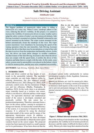
- 1. International Journal of Trend in Scientific Research and Development (IJTSRD) Volume 6 Issue 7, November-December 2022 Available Online: www.ijtsrd.com e-ISSN: 2456 – 6470 @ IJTSRD | Unique Paper ID – IJTSRD52394 | Volume – 6 | Issue – 7 | November-December 2022 Page 707 Safe Driving Assistant Abdülkadir Çakir Isparta University of Applied Sciences, Faculty of Technology, Department of Electrical and Electronics Engineering, Isparta, Turkey ABSTRACT The biggest problem of motorcycle riders today is riding a motorcycle on a rainy day. When it rains, raindrops adhere to the visor, reducing the driver's visibility. In this project, it is aimed to increase the visibility of motorcycle drivers in rainy weather and to adapt the safety systems of today's cars into motorcycle helmets. Safe Driving Assistant is mounted on a helmet. Rainfall is detected by rain sensors mounted on the helmet. The wiper system mounted on the helmet automatically cleans the raindrops on the visor. The wiper system maximizes visor cleanliness by increasing the speed of the wiping operation when the rain intensifies. Safe Driving Assistant informs the driver that there may be precipitation or icing in line with the data it receives from the temperature and humiditysensors. In this way, the driver can learn about changes in weather conditions. Another feature of the Safe Driving Assistant is that when the driver does not comply with the speed limits, it notifies the driver of this situation and helps them to comply with the rules. In this study, some safety systems used in automobiles were placed on the helmet, which is vital for motorcyclists, and the tests were completed successfully. KEYWORDS: Safe Driving, Visibility, Rain, Speed Rules How to cite this paper: Abdülkadir Çakir "Safe Driving Assistant" Published in International Journal of Trend in Scientific Research and Development (ijtsrd), ISSN: 2456-6470, Volume-6 | Issue-7, December 2022, pp.707-711, URL: www.ijtsrd.com/papers/ijtsrd52394.pdf Copyright © 2022 by author (s) and International Journal of Trend in Scientific Research and Development Journal. This is an Open Access article distributed under the terms of the Creative Commons Attribution License (CC BY 4.0) (http://creativecommons.org/licenses/by/4.0) 1. INTRODUCTION Safety and driver comfort are key targets of new trends in the automobile industry. The automatic wiper controller not only helps improve safety by reducing distractions, but also improves overall comfort (Biswas et al., 2022; Zheng et al., 2015). Such automatic control exists, but has limitations of high cost and low efficiency (Madhu, Pradeepika, & Sandhiya, 2019). In this work, there is an automatic wiper controller based on a resistive rain sensor, which is cost effective, efficient and has a wide output range. An equivalent electrical and mathematical model of the sensor is developed, simulated and practically verified. The rain sensor has a predetermined geometry. Therefore, rainwater forms a layer on the sensor surface, causing its resistance to change non-linearly. To increase the overall efficiency of the system, it is necessary to linearize the sensor response. It is achieved by using the electrical equivalent model of the sensor and by means of the appropriate linearization circuit. In addition, a customized embedded system has been developed using a PIC microcontroller to obtain the motor speed variation based on the sensor output. The proposed system has been rigorously tested in a small segment car for its performance. It has been observed that the developed system works satisfactorily in various precipitation scenarios (Joshi, Jogalekar, Sonawane, Sagare, & Joshi, 2013). Motorcycle helmets are vital for motorcycle riders. The main purpose of wearing a motorcycle helmet is to minimize skull injuries in the event of an accident and to prevent permanent damage to this area. The internal structure of motorcycle helmets is shown in Figure 1. Figure 1. Helmet internal structure (Msf, 2021) Due to the sticking of rain droplets on the visor during precipitation, the visibility level of motorcycle drivers decreases and this makes it difficult for them to drive safely. Motorcycle riders keep their attention from the IJTSRD52394
- 2. International Journal of Trend in Scientific Research and Development @ www.ijtsrd.com eISSN: 2456-6470 @ IJTSRD | Unique Paper ID – IJTSRD52394 | Volume – 6 | Issue – 7 | November-December 2022 Page 708 road by looking at the speedometer at certain intervals in order to comply with the speed limits. While looking at the speedometer, they are unlikelyto notice a living creature or a vehicle in front of them. Safe driving assistant aims to prevent these problems. The rain sensor placed on the helmet detects the rain and the wiper system placed on the helmet tries to increase the visibility by cleaning the rain droplets on the visor. The temperature and humidity sensor inside the helmet calculates the probability of precipitation and icing by measuring the temperature and humidity. It monitors the speed of the driver with the GPS placed inside the helmet and gives an audible and light warning to the driver with the RGB LED module and the buzzer in case of speed limit violation. This ensures that the driver's attention is not diverted from the road. Similar to the wiper system used in today's cars shown in Figure 2, the arm placed on the motorcycle helmet and the wiper blade placed on the arm will play a role in increasing the driving safety of the driver by increasing the driver's vision level by removing the rain particles adhering to the visor over the visor. Thanks to the GPS module placed behind the helmet, when the driver exceeds the speed limit, it will warn the driver with the help of RGB Led and Buzzer and will help him comply with the speed rules. The possibility of icing and rain will be calculated by the temperature and humidity sensor and the driver will be informed with the help of the RGB Led module. Figure 2. The wiper system used in automobiles (Anonymous, 2020) 2. SAFE DRIVING ASSISTANT 2.1. Findings from the Wiper System A wiper mechanism is designed to clean the rain droplets on the visor. This wiper mechanism consists of servopan, servo motor, wiper arm and wiper sponge. First, the servo motor and servopan assembly was carried out. The wiper arm was mounted on the servopan by means of a rectangular plastic piece. A wiper sponge was placed on the wiper arm to contact and clean the visor, and the wiper system was connected to the helmet as in Figure 3. The analog data obtained from the rain sensor placed on the helmet were connected to the conditions in the development board Arduino, and the operating speed and angle of the servo motor were determined as in Table 1. In the tests, it was observed that the servo motor cleaned the rain droplets from the visor, but the pressure on the visor caused the servo motor to be forced and the movement of the wiper arm restricted. In this case, by changing the angle of the wiper arm, this pressure is reduced and the wiper arm can be moved comfortably. Figure 3. Installation of the wiper system Amount of Rain Servo Motor Working angle (degrees) Wiper Duration (sn) No Rain 0 - Rain 120 1 Heavy Rain 90 0 Table 1. Servo motor operating angle and dwell time
- 3. International Journal of Trend in Scientific Research and Development @ www.ijtsrd.com eISSN: 2456-6470 @ IJTSRD | Unique Paper ID – IJTSRD52394 | Volume – 6 | Issue – 7 | November-December 2022 Page 709 2.2. Findings Obtained from the GPS Sensor It is mounted on the inner top of the helmet together with the GPS system antenna. 5V and GND connection was made on the Arduino, then the RX and TX pins were connected to communicate with the Arduino development board, and the 10th and 11th pins of the Arduino were defined as software RX and TX. Using the Tiny GPS library, the accuracy of the data from the GPS sensor was checked as in Figure 4. Then, only the speed data was transferred to the Arduino development board. In cases where the speed obtained from the GPS sensor exceeds 50km/h, conditional loops were used to warn with RGB LED and buzzer, and real-time testing was performed with the car. As a result of these tests, it was seen that the speed data obtained from the gps sensor deviated when compared to the automobile, but gave close results. Figure 4 Communication of gps sensor with arduino 2.3. Findings Obtained from the Temperature and Humidity Sensor The temperature and humidity sensor is mounted on the back of the helmet. The 5V and GND pins of the temperature and humidity sensor were fed through the Arduino, then the signal leg was connected bydefining pin 3 on the Arduino as input. Measurements Arduino. Controls are provided via the serial screen in the IDE interface. When the temperature drops below 4 degrees, the algorithm that provides a blue light warning to the RGB led module was added to the Arduino and tested as in Figure 5. As a result of these tests, it was seen that the instantaneous temperature and humidity values obtained from the internet gave close results. Figure 5. Testing the measurements of the temperature and humidity sensor on the serial monitor 2.4. Findings Obtained From RGB Led Module Rain information, icing information and speed violation information are given to the driver via RGB led module. The development board Arduino checks the presence of negative conditions with the feedback it receives from the sensors. These feedbacks come from the analog, digital and communication pins of the development board. By giving power to the digital outputs on the development board, the light is turned on by selecting the appropriate color tone over the RGB led module. The light color formed in adverse conditions and the color mixture formed by the combination of more than one unfavorable condition are as indicated in Table 2.
- 4. International Journal of Trend in Scientific Research and Development @ www.ijtsrd.com eISSN: 2456-6470 @ IJTSRD | Unique Paper ID – IJTSRD52394 | Volume – 6 | Issue – 7 | November-December 2022 Page 710 Adverse Conditions Red Light Green Light Blue Light Warning Light Color to Occur No Status - - - - Rain - + - Green Icing - - + Blue Speed Limit Violation + - - Red Speed Limit Violation and Rain + + - Yellow Speed Limit Violation and Icing + - + Purple Icing and Rain - + + Turquoise Table 2. Warning lights and conditions 2.4. Software and Algorithm of the System The system needs a microcontroller and this microcontroller needs a software in order to fulfill its intended tasks. Before the system was programmed for stable operation, an algorithm was created as shown in Figure 6. In the algorithm, the desired conditions of the data received from the sensors are expected to be met and a function is run according to the sensor when the conditions are met. When the rain sensor detects rain, the wiper system works and starts to wipe the visor glass, while giving information to the driver by flashing a green light on the RGB LED. The GPS sensor informs the driver by flashing a red light on the buzzer and RGB LED in case the driver goes over 50kmh. The temperature and humidity sensor instantly monitors the temperature and humidity and warns the driver by flashing a blue light on the RGB LED to warn the driver of icing in cases where the temperature drops below 4 degrees. As can be seen in Figure 7, since there is a simultaneous data flow from more than one sensor used and the Arduino is a development board that cannot perform multitasking, each of the sensors was enabled to communicate with the Arduino at different times and repeatedly. In this way, it is ensured that the system works without any command jumps. Figure 6. Software flow chart Figure 7. System block diagram 3. CONCLUSIONS As a result of the researches in the literature, it has been seen that the sensors of the Safe Driving Assistant work independently from each other. In this study, all sensors were brought together and the wiper system was added to increase the level of driving safety. In this study, it was seen that the wiper system placed on the helmet works automatically in rainy weather and plays a role in increasing the level of visibility by cleaning the water droplets falling on the visor. The data received from the rain sensor were viewed on the Serial Port screen of the Arduino. IDE program. Heavy rain and drizzle simulation is carried out in a home environment and Arduino. Calibrations were performed on the IDE and run successfully. The GPS sensor in the Safe Driving Assistant is hidden in the helmet and then connected to the Arduino. The position and speed data obtained from the GPS sensor were checked from the Serial port screen of the Arduino. IDE program. The test environment was created with the speed data taken from the GPS sensor. The data taken from the car and the GPS sensor were compared and it was seen that there were deviations. In order to successfully complete the project, it is planned to test alternative GPS sensors. Tests of the Temperature and Humidity sensor were carried out in the open air and compared with the data received from the internet environment, it was seen that it worked without any problems. It was placed in
- 5. International Journal of Trend in Scientific Research and Development @ www.ijtsrd.com eISSN: 2456-6470 @ IJTSRD | Unique Paper ID – IJTSRD52394 | Volume – 6 | Issue – 7 | November-December 2022 Page 711 the refrigerator for the tests of the temperature sensor in the home environment and it was observed that it gave a warning on the RGB Led module at the right time. It was placed on the back surface of the helmet where the Safe Driving Assistant will be installed so that the Temperature and Humidity sensor is not affected by the wind while driving. In this study, some safety systems used in automobiles were placed in the helmet, which is vital for motorcyclists, and their tests were successfully completed. Thanks to this study, the working types of automobile security systems, possible problems and solutions to these problems were investigated and gains were obtained in the programming of microcontrollers. References: [1] Anonymous. (2020). Silecek Sistemi Nedir? Retrieved from https://www.motordersi.com/silecek-sistemi- nedir/ [2] Biswas, N., Tiwari, S., Singh, S., Sonwani, S., Rizvi, T., & Bhonsle, D. (2022). Automatic Rain sensing wiper using Arduino. International Journal of Innovative Research in Engineering, 3(2), 107-109. [3] Joshi, M., Jogalekar, K., Sonawane, D., Sagare, V., & Joshi, M. (2013). A novel and cost effective resistive rain sensor for automatic wiper control: circuit modelling and implementation. Paper presented at the 2013 Seventh International Conference on Sensing Technology (ICST). [4] Madhu, A., Pradeepika, R., & Sandhiya, P. (2019). Automation in the body control module of a car. International Journal of Advance Research, Ideas and Innovations in Technology, 5(2), 546-549. [5] Msf. (2021). Personal Protective Gear for the Motorcyclist. Retrieved from https://msf- usa.org/wp-content/uploads/2021/07/AI7- pdf.pdf. https://msf-usa.org/wp- content/uploads/2021/07/AI7-pdf.pdf [6] Zheng, D., Chen, S., Yu, H., Chen, Q.-Y., Liu, L., Li, X., & Li, J. (2015). Research and Design of Automobile’s Automatic Wipers Based on FPGA. Paper presented at the 3rd International Conference on Material, Mechanical and Manufacturing Engineering (IC3ME 2015).