Volume Booster for Pneumatic Control Systems
•
0 likes•585 views

ControlAir Inc. is a leading manufacturer of precision air pressure regulators, I/P transducers, E/P transducers, P/I transducers, valve positioners, air relays, volume boosters, air filter regulators and frictionless diaphragm air cylinders.

Recommended
More Related Content
What's hot
What's hot (19)
Similar to Volume Booster for Pneumatic Control Systems
Similar to Volume Booster for Pneumatic Control Systems (20)
More from Hile Controls of Alabama, Inc.
More from Hile Controls of Alabama, Inc. (20)
Recently uploaded
Recently uploaded (20)
Volume Booster for Pneumatic Control Systems
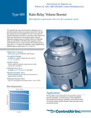
- 1. Type 600 Ratio Relay Volume Booster Meet high flow requirements with a low flow pneumatic signal. The Type-600 ratio relay volume booster is designed to use a pneumatic signal to produce an output pressure which has high flow capacity and can be amplified. This unit is most useful for systems requiring the conversion of a low flow control signal to the higher flow requirements of an operating system. Using an independent supply pressure for greater volume, the Type-600 relays up to 50 SCFM (1,400 Nl/min) flow capacity to a final control element such as a valve actuator. The standard signal to output ratio is 1:1, however, the Type-600 is also available with an amplified signal to output ratio of 1:2, 1:3 and 1:6. F E A T U R E S •High Flow Capacity Allows flows up to 50 SCFM (1,400 Nl/min) •Amplified Output Available in a signal to output pressure ratio of 1:1, 1:2, 1:3 and 1:6 •Stable Output Venturi aspirator maintains output pressure under varying flow conditions •Multiple Port Sizes Available in 1/4", 3/8" and 1/2" NPT/BSP •Balanced Supply Valve Rolling diaphragm design makes unit insensitive to supply pressure variation •Optional Negative Bias 4 psi (0.3 bar) negative bias option allows "zero" of I/P's Flow Characteristics RegulatedPressurepsig 1:3 1:6 1:1 1:2 Flow scfm Supply = 100 psig 0 5 10 15 20 25 30 35 40 45 50 25 20 15 10 5 0 20 15 10 5 Applications The Type-600 is used extensively for increased flow capacity, pressure amplication, or remote pressure control applications. This includes web tensioning, roll loading, control valve acuators, I/P volume boosting, cylinder actuation, clutch and brake control, and gas flow control. Hile Controls of Alabama, Inc. Pelham, AL USA | 800-536-0269 | www.hilealabama.com
- 2. Type 600 Dimensions Ratio 1:1 1:2 1:3 1:6 Flow capacity, SCFM (Nl/min) 50 (1,400) Exhaust capacity, SCFM (Nl/min) 15 (425) 15 (425) 15 (425) 10 (283) Sensitivity, inches water (cm) .25 (.64) .50 (1.3) .75 (1.9) 1.50 (3.8) Ratio accuracy (%) - % of output span with 3-15 psig (0.21-1.05 BAR) signal 1.0 1.12 1.25 2.0 Zero error (%) - % of output span with 3-15 psig (0.2-1.05 BAR) signal 2.0 2.12 2.25 3.0 Effect of supply pressure change of 50 psig (3.5 BAR) 0.1 psi 0.2 psi 0.3 psi 0.6 psi Air Consumption, maximum Steady state:1.0to10.0scfh(0.5 to 5 Nl/min), depending on output pressure range Max. supply pressure, psig (BAR) 250 (17.5) Max. signal pressure, psig (BAR) 150 (10.34) 75 (5.17) 50 (3.44) 25 (17.2) Ambient temperature limits, °F (°C) -40 to 160 (-40 to 71) Weight, lbs. (gm) 1.4 (6.35) Port sizes 1/4", 3/8", 1/2" NPT/BSP Mounting options Pipe, panel or bracket Materials Body: Diecast aluminum Internal Components: Stainless steel, brass, plated steel, acetal Diaphragm: Nitrile elastomer & polyester fabric Ordering Information Part Number Port Size NPT Ratio 600-BA, 600-CA, 600-DA 1/4", 3/8", 1/2" 1:1 600-BB, 600-CB, 600-DB 1/4", 3/8", 1/2" 1:2 600-BC, 600-CC, 600-DC 1/4", 3/8", 1/2" 1:3 600-BD, 600-CD, 600-DD 1/4", 3/8", 1/2" 1:6 Options (Add proper letter at end of model number) Z - Negative Bias: -4 ± 1 psi bias E - Tapped Exhaust: Allows captured exhaust. 1/8" NPT port U - BSP Porting (1/4", 3/8", 1/2") X - ATEX 94/9/EC Accessories G - Pressure Gauge: 2" face, back mounted. Dual scale 0-15 psi range: P/N 446-725-003 0-30 psi range: P/N 446-725-004 0-60 psi range: P/N 446-725-001 0-160 psi range P/N 446-725-002 B - Mounting Bracket: P/N 446-707-025 Warranty ControlAir, Inc. products are warranted to be free from defects in materials and workmanship for a period of eighteen months from the date of sale, provided said products are used according to ControlAir, Inc. recommended usages. ControlAir, Inc.'s liability is limited to the repair, purchase price refund, or replacement in kind, at ControlAir, Inc.'s sole option, of any products proved defective. ControlAir, Inc. reserves the right to discontinue manufacture of any products or change products materials, designs or specifications without notice. Note: ControlAir does not assume responsibility for the selection, use, or maintenance of any product. Responsibility for the proper selection, use, and maintenance of any ControlAir product remains solely with the purchaser and end user. 8 Columbia Drive / Amherst, NH 03031 USA Website: www.controlair.com Email: sales@controlair.com 603-886-9400 FAX 603-889-1844 Type 600 Specifications P/N 441-625-006 08/08/14 100 psig (48 bar) supply, 20 psig (1.4 bar) output Dimensions are in mm Downstream 5 psig (0.34 bar) above set pressure 2.25 57.15 1.88 47.8 DIA. MOUNTING BRACKET (OPTIONAL) (2) HOLES FOR 5/16" BOLT Signal Diaphragm Relief Valve Exhaust Port Control Diaphragm Supply Valve Balance Diaphragm Aspirator Tube Supply Pressure Signal Pressure Output Pressure Atmospheric Pressure PRINCIPLE OF OPERATION When pressure is introduced through the signal port of the Type-600, a downward force on the upper diaphragm area is created. This force is balanced by the output pressure acting against the lower control diaphragm area. The ratio of signal pressure to output pressure is determined by the ratio of the effective areas of the upper and lower diaphragms. If signal pressure is increased above the output pressure there is a net downward force on the diaphragm assembly causing the supply valve to open. Output pressure increases until equalibrium is achieved. When signal pressure is decreased below the output pressure, the diaphragm assembly rises, allowing output air to exhaust through the vent on the side of the relay.