Turbine flow meters for gas service from Hoffer
•
0 likes•711 views

Hoffer Flow Controls manufactures high precision turbine flowmeters for the cryogenic industry and is the world leader in turbine flowmeter technology for the measurement of clean liquids and gases throughout the processing industries.

Recommended
Recommended
More Related Content
What's hot
What's hot (20)
Similar to Turbine flow meters for gas service from Hoffer
Similar to Turbine flow meters for gas service from Hoffer (20)
More from Flow-Tech, Inc.
More from Flow-Tech, Inc. (17)
Recently uploaded
Recently uploaded (20)
Turbine flow meters for gas service from Hoffer
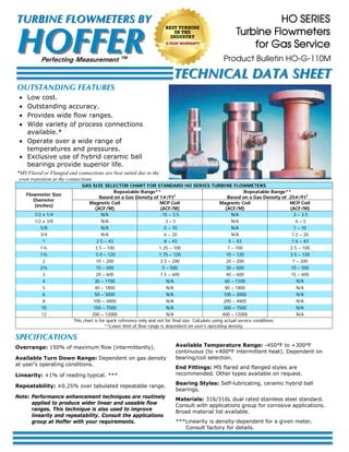
- 1. SPECIFICATIONS Overrange: 150% of maximum flow (intermittently). Available Turn Down Range: Dependent on gas density at user‘s operating conditions. Linearity: ±1% of reading typical. *** Repeatability: ±0.25% over tabulated repeatable range. Note: Performance enhancement techniques are routinely applied to produce wider linear and useable flow ranges. This technique is also used to improve linearity and repeatability. Consult the applications group at Hoffer with your requirements. Available Temperature Range: -450°F to +300°F continuous (to +400°F intermittent heat). Dependent on bearing/coil selection. End Fittings: MS flared and flanged styles are recommended. Other types available on request. Bearing Styles: Self-lubricating, ceramic hybrid ball bearings. Materials: 316/316L dual rated stainless steel standard. Consult with applications group for corrosive applications. Broad material list available. ***Linearity is density-dependent for a given meter. Consult factory for details. HO SERIES Turbine Flowmeters for Gas Service OUTSTANDING FEATURES Low cost. Outstanding accuracy. Provides wide flow ranges. Wide variety of process connections available.* Operate over a wide range of temperatures and pressures. Exclusive use of hybrid ceramic ball bearings provide superior life. GAS SIZE SELECTOR CHART FOR STANDARD HO SERIES TURBINE FLOWMETERS Flowmeter Size Diameter (inches) Repeatable Range** Based on a Gas Density of 1#/Ft3 Repeatable Range** Based on a Gas Density of .25#/Ft3 Magnetic Coil (ACF/M) MCP Coil (ACF/M) Magnetic Coil (ACF/M) MCP Coil (ACF/M) 1/2 x 1/4 N/A .15 – 3.5 N/A .3 – 3.5 1/2 x 3/8 N/A .3 – 5 N/A .6 – 5 5/8 N/A .5 – 10 N/A 1 – 10 3/4 N/A .6 – 20 N/A 1.2 – 20 1 2.5 – 43 .8 – 43 5 – 43 1.6 – 43 1¼ 3.5 – 100 1.25 – 100 7 – 100 2.5 – 100 1½ 5.0 – 120 1.75 – 120 10 – 120 3.5 – 120 2 10 – 200 3.5 – 200 20 – 200 7 – 200 2½ 15 – 500 5 – 500 30 – 500 10 – 500 3 20 – 600 7.5 – 600 40 – 600 15 – 600 4 30 – 1100 N/A 60 – 1100 N/A 5 40 – 1800 N/A 80 – 1800 N/A 6 50 – 3000 N/A 100 – 3000 N/A 8 100 – 4800 N/A 200 – 4800 N/A 10 150 – 7500 N/A 300 – 7500 N/A 12 200 – 12000 N/A 400 – 12000 N/A This chart is for quick reference only and not for final size. Calculate using actual service conditions. **Lower limit of flow range is dependent on user’s operating density. *MS Flared or Flanged end connections are best suited due to the even transition at the connections. Product Bulletin HO-G-110M HOFFERHOFFER TURBINE FLOWMETERS BYTURBINE FLOWMETERS BY Perfecting Measurement TM TECHNICAL DATA SHEETTECHNICAL DATA SHEET BEST TURBINE IN THE INDUSTRY 5-YEAR WARRANTY
- 2. MODEL HO ( A ) X ( B ) - ( C ) - ( D ) - ( E/F/G ) - ( H ) - ( I ) A. End Fitting Size B. Flowmeter Size C. Blade Angle (See Note 1) D. Bearing Type (BP) (CB) E. Pickup Coils (1M) (2M) (1MC3PA) (2MC3PA) (1MC3PAHT) (2MC3PAHT) (1HTM) (2HTM) (1ISM) (2ISM) (1ISM-ATEX (2ISM-ATEX) _(RP___) _(_____) (P) (-ATEX) One Magnetic Coil Two Magnetic Coils One RF Coil Two RF Coils One High Temp RF coil Two High Temp RF coils High Temperature Magnetic Coil Two High Temperature Magnetic Coils Intrinsically Safe Mag Coil Two Intrinsically Safe Mag Coils One ISM ATEX coil Two ISM ATEX coils Redi-Pulse Coil (See Redi-Pulse Technical Data Sheet RP-XXX) Intrinsically Safe Redi-Pulse Coil (See I.S. Redi-Pulse Technical Data Sheet IRP-XXX) Pigtail or Flying Leads, Add-P and the Length of leads after any coil except the high temperature coils. Add after coil part no. when using ATEX enclosure mounted on meter. F. Coil Spacing, Mechanical Degrees Apart ( ) Factory Assigned. Spacing required when meter has two pickup coils. If second coil not required skip option (F). G. Riser and Explosion-Proof Coil Enclosures (X) (X-ATEX) (XE2) (X-ATEX)E2 (X8S) (X8S-ATEX) 1" MNPT riser, welded to body. Required for all types of enclosures. 3/4" MNPT riser, welded to the body. 1" MNPT riser with E2 enclosure. (See Chart)* 3/4" MNPT riser with E2 enclosure. (See Chart)* 8" Long S/S 1" MNPT riser. (For fluid temperatures below -40°F (-40°C) or above +140°F +60°C). 8" Long S/S 3/4" MNPT riser. (For fluid temperatures below -40°F (-40°C) or above +140°F +60°C). H. End Fitting Types (MS) (NPT) (F___) (DN_/PN_CS/SS) (W_) 37 Deg. Male Flare Per MS33656 Male National Pipe Thread (See Note 3 below) Raised Face Flange per ANSI (See Chart **) DN=Metric size, PN=Flange pressure rating (in DIN std.) and select material Wafer Style Body (Use 1, 3, 6, 9, 15 or 25 after “W” to indicate flange weight wafer meter will be used with) I. Special Features (CE) (PED-CE) (SEP-CE) (PT) (PG) (SP) (EXP) (X) CE Mark - Required for Europe. PED Mark - Required for Europe. Sound engineering practice. ¼" FNPT Pressure Tap (AGA Compliant). Premier Gas turbine for improved accuracy of ±0.5%, requires actual or natural gas calibration. Please see HO-PG-100 for more information. Any special features that are not covered in the model number, use a written description of –SP. CSA Explosion-Proof Certification. (See Chart)*** No Special Features Self-lubricating, ceramic hybrid ball bearings, sizes 1/4" thru 1". Self-lubricating, ceramic hybrid ball bearings, sizes 1-1/4" thru 12". GAS TURBINE FLOWMETER MODEL NUMBERING SYSTEM Request HO-L-110 Technical Data Sheet for complete specifications for HO Series for Liquid Service. Select one: (1) 150# Flanges (3) 300# Flanges (4) 400# Flanges (6) 600# Flanges (9) 900# Flanges (15) 1500# Flanges (25) 2500# Flanges Select One: (SS) Stainless Steel (CS) Carbon Steel Note: 316/316L SS flanges are standard, add-304 at end of model # if 304 flanges are required. **Pressure Rating/Flange Material Include “F”, number indicating pressur rating, and flange material. (i.e., -F1SS-) Notes: 1. Blade Angle determined by density, assigned by factory or use of gas sizing program. 2. Turbine sizes ¼" through ¾" must be equipped with MC3PA coil. 1" through 3" may be recommended for MC3PA coil depending on gas density and desired turndown range. 3. NPT not recommended for gas service due to possible uneven transition at NPT connections. The quality system covering the design, manufacture and testing of our products is certified to International Standard ISO 9001. *E2 EXPLOSION-PROOF/FLAME-PROOF ENCLOSURE WITH 3/4” FNPT MOUNT AND 3/4" CABLE ENTRY RATINGS: FM: CSA: ATEX: IEC: CLASS I, DIV. 1, GR. ABCD, CLASS II/III, DIV. 1, GR, EFG, TYPE 4X CLASS I, DIV. 1, GR. ABCD, CLASS II, DIV. 1, GR. EFG, CLASS III, TYPE 4X EX D IIC, CLASS I, ZONE 1, IP 66 EX II 2GD Ex d tD IIC, IP66/68 EX D IIC IP68 The specifications contained herein are subject to change without notice and any user of said specifications should verify from the manufacturer that the specifications are currently in effect. Otherwise, the manufacturer assumes no responsibility for the use of specifications which may have been changed and are no longer in effect. HOFFER FLOW CONTROLS, INC.HOFFER FLOW CONTROLS, INC. 107 Kitty Hawk Lane, P. O. Box 2145 Elizabeth City, NC 27906-2145 800-628-4584 252-331-1997 FAX 252-331-2886 www.hofferflow.com email: Info@hofferflow.com *** CLASS I, DIV. 1, GR. ABCD; CLASS I, DIV. 2, GR. ABCD; CLASS II, DIV. 1, GROUPS EFG CANADA: CLASS I, ZONE 1 & 2, Ex d II C USA: CLASS I, ZONE 1 & 2, AEx d II C