Line Differential - Test report for Alstom make Micom P546 relay
•
20 likes•4,443 views

Sample test report for alstom make micom P546 with some small explanation about how the testing is done.

Recommended
Recommended
More Related Content
What's hot
What's hot (20)
Viewers also liked
Similar to Line Differential - Test report for Alstom make Micom P546 relay
Similar to Line Differential - Test report for Alstom make Micom P546 relay (20)
Recently uploaded
Recently uploaded (20)
Line Differential - Test report for Alstom make Micom P546 relay
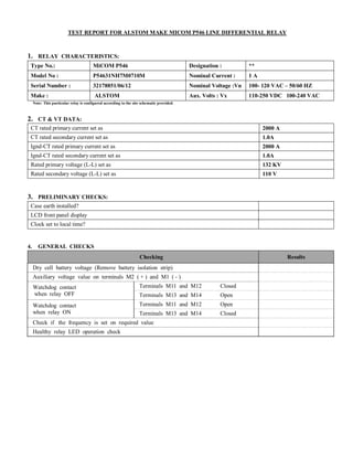
- 1. TEST REPORT FOR ALSTOM MAKE MICOM P546 LINE DIFFERENTIAL RELAY 1. RELAY CHARACTERISTICS: Type No.: MiCOM P546 Designation : ** Model No : P54631NH7M0710M Nominal Current : 1 A Serial Number : 32178851/06/12 Nominal Voltage :Vn 100- 120 VAC – 50/60 HZ Make : ALSTOM Aux. Volts : Vx 110-250 VDC 100-240 VAC Note: This particular relay is configured according to the site schematic provided. 2. CT & VT DATA: 3. PRELIMINARY CHECKS: 4. GENERAL CHECKS Checking Results Dry cell battery voltage (Remove battery isolation strip) Auxiliary voltage value on terminals M2 ( + ) and M1 ( - ) Watchdog contact when relay OFF Terminals M11 and M12 Closed Terminals M13 and M14 Open Watchdog contact when relay ON Terminals M11 and M12 Open Terminals M13 and M14 Closed Check if the frequency is set on required value Healthy relay LED operation check CT rated primary current set as 2000 A CT rated secondary current set as 1.0A Ignd-CT rated primary current set as 2000 A Ignd-CT rated secondary current set as 1.0A Rated primary voltage (L-L) set as 132 KV Rated secondary voltage (L-L) set as 110 V Case earth installed? LCD front panel display Clock set to local time?
- 2. 5. DISPLAY READINGS Circuit Injected Value Phases Expected Value Displayed Value Primary Voltage 63.5 Phase A / 0° Phase B / -120° Phase C / 120° VAN 76.21 kV 76.23 kV VBN 76.21 kV 76.25 kV VCN 76.21 kV 76.30 kV VAB 132.0 kV 132.1 kV VBC 132.0 kV 132.1 kV VCA 132.0 kV 132.1 kV Current 1.0 A Phase A / 0° Phase B / -120° Phase C / 120° IA 2000 A 2002 A IB 2000 A 1999 A IC 2000 A 2007 A IN 0.00 A 10.39 A Frequency 60.0 Hz - 60.0 Hz 60.0 Hz MW Va, Vb, Vc = 57.74V Ia, Ib, Ic =1A Angle between V&I = 0.0 degree - 457.3 MVA 458.1 MVA MVAR - 0.0 MVAR -0.12 MVAr MVA - 457.3 MW 458.3 MW 6. FUNCTIONAL TESTS 6.1 Current differential bias characteristic (87-1) Setting: Item Description Setting 1 IS1 0.20 A 2 Is2 2.0 A 3 K1 30 % 4 K2 150 % 5 T 0 Sec Pick-up & Time test:- *NOTE: The Relay will be tested at loopback internal mode It should be noted that the minimum operating current is related, but not equal to the Is1 SETTING Consider a single end fed fault with no load but fault current, I:- |Idiff| = I |Ibias| = ½I Assuming |Ibias| < Is2, then, using the equations from section 2.1( from manual ), the relay will operate if:- |Idiff| > k1.| Ibias| + Is1 or I > k1.½I + Is1 or I> Is1 / (1 - 0.5 k1) The minimum operating current is therefore a function of the Is1 and k1 settings. Since k1 is recommended to be set to 30%, the minimum operating current will be:- Imin = 1.176 1s1 I Diff I > ( k1 * I I Bias I+ Is1 )/2 = 0.118 A Fault Type Expected Pickup In Amp Actual Pickup In Amp Drop-off In Amp Expected Trip Time in m-sec Actual Trip Time in m-sec at 2 x I Pickup A-N 0.118 A 0.120 0.088 <40 ms 31 B-N 0.118 A 0.120 0.089 <40 ms 28 C-N 0.118 A 0.120 0.088 <40 ms 35
- 3. Lower slope test (Injected current < Is2) |Ιdiff| >( k1.| Ιbias| + Ιs1)/2=0.25 A Bias current injected in phase (Amps) Differential current injected in phase Expected differential current for tripping (Amp) Measured value of diff. current (Amp) Expected Trip Time in m-sec Actual Trip Time in m-sec at 2 x I Pickup A B C A B C 00 1.0 00 X 00 00 0.25 0.254 <40 ms 32 00 00 1.0 00 X 00 0.25 0.253 <40 ms 28 1.0 00 00 00 00 X 0.25 0.252 <40 ms 29 Upper slope test (Injected current > Is2) |Ιdiff| > (k2.| Ιbias| - (k2 - k1). Ιs2 + Ιs1)/2=1.15A Bias current injected in phase (Amps) Differential current injected in phase Expected differential current for tripping (Amp) Measured value of diff. current (Amp) Expected Trip Time in m-sec Actual Trip Time in m-sec at 2 x I Pickup A B C A B C 00 3.0 00 X 00 00 1.15 1.158 <40 ms 24 00 00 3.0 00 X 00 1.15 1.159 <40 ms 25 3.0 00 00 00 00 X 1.15 1.155 <40 ms 25 7.1 Distance protection (21-1) – Attachments- Resistive Zone Reach check (quadrilateral characteristics only) Item Description Checked 1 Print out from FREJA attached Impedance tolerance: +/- 5% for zone 1 and +/- 10 % for other zones. PH-E (G) : - Resistive reach: Rn (Ω/Loop) = RGn (Ω)/ (1+Kz). - Reactive reach: Xn (Ω/Loop) = Zn (Ω) * sin (ΦLG) - Compensation factor KZ = 1/3((Zo-Z1)/Z1). - Line impedance ZLG = RLG+J XLG = 1/3(2*ZLph +ZOL) PH-PH (PH): - Resistive reach: Rphn (Ω/ph) = Rphn (Ω/Loop) / 2. - Reactive reach: Xn (Ω) = Zn (Ω) * sin (ΦLph). - Line impedance ZLph = RLph+J XLph. 7.2 Distance OPERATING TIME TESTING: Item Description Checked 1 Print out from FREJA attached 7.3 Distance protection SCHEME TESTING: Setting: § Aid Dist delay =0.0 m sec I. Permissive Over Reach Scheme: Send logic: Carrier Send = Z2 : 34 m sec Trip logic: Trip = Z2 + CR : 38.0 m sec (Aid Dist Delay + Trip Time = 0+35 msec) Trip logic: Trip = Z2 w/o CR : 434 m sec
- 4. II. Current Reversal Logic Check (Permissive Over Reach Scheme): § Apply a reverse / forward fault to check: For All Zone Fault type t rev guard setting (m sec) t rev guard measured (m sec) (trev+Aid Delay) Reverse/ forward 70 86 (70+Trip) Test : Reverse zone in sequence 1, Iin sequence 2 = Z2+ carreier receive 7.4 Distance protection Power Swing Blocking - PSB Setting : Enable Slow Swing Blocked zone for Power Swing Blocking Z1-Z2-Z3-Z4 = OK Power swing blocking delay time Set Measured ---- ---- 7.5 Distance protection Switch On To Fault - SOTF SOTF BY C.B CLOSING BI: Zone concerned by SOTE: Z1 SOTF pulse time set = 500 ms SOTF pulse time measured = 539 ms Check SOTF work with concerned zone= [ Z1 - OK ] Check SOTF trip time at fault at Z1 = 24 ms Check SOTF trip time at fault at Z2 = 436 ms Check SOTF trip time at fault at Z3 = 835 Sec Check SOTF trip time at fault at Z4 = 1.228 Sec Configure BI. (set SOTF) DDB# 488 as CB manual close command to check first state To measure SOTF pulse time configure BO as SOTF ACTIVE and use it as dual contact 7.6 VT Supervision Test: 7.6.1 Loss of one or two phases test: Fixed setting V2=10V -Apply 3 Phase rated voltage (Ur V) with balanced angles. -Apply 3 Phase rated current (Ir A) with balanced angles. -for the phase under test start decrease the voltage on one phase and / or two phases till you get Internal fuse fail (fuse fail without time lag). - For time test inject voltage more than V2.and stop freja BO. VTF alarm Fixed setting: V2 = 10 volt, I2> inhibit less than setting.=50 mA Phase Normal Voltage Pick up Drop off Set Time (Sec) Measured Time (Sec) One phase 63.5 33.58 35.12 5.0 5.022 Two phase 63.5 33.58 35.10 5.024 - CHECK THE FUSE FAIL BLOCKING BY I2> inhibit (simulate 3 phase voltage to get fuse Fail, for I2> Apply 3 Phase equal current (Ir A) with balanced angles and increase one phase to get I2 more than the setting Value it will inhibit fuse fail then decrease again phase till you get fuse fail -Check the relay trip unblocking during the internal fuse fail by any fault : [ ok ] Simulate 2 stages: - stage 1; inject 3 phase voltage to get fuse fail and zero current. - stage 2; inject the same voltage as in stage 1, inject 3 phase current to get a value greater than I2> inhibit. 7.6.2 Loss of all 3 phase voltages under load condition test (detect 3p): Fixed Setting: a- for fuse fail pick up; V1=10 volts. b- for fuse fail reset; V1=30 volts. Pick up (v) Reset (v) 10.0 30.03 Check the blocking of the relay when the general block functions (VT MCB TRIP) is activated [ ok ]
- 5. 7.7.1 Distance Directional Test: Fixed Direction Measured Direction Forward 330° - 150° Forward 329.6 – 149.6 Reverse 150° - 330° Reverse 149.7 – 329.5 7.7.2 Distance Minimum Pick up current Test: Zones Current setting for Phase Fault (mA) Measured Pick up current(mA) Current setting for Ground Fault (mA) Measured Pick up current(mA) Z1 500 505 250 254 Z2 500 504 250 252 Z3 500 504 250 252 ZP --- --- --- --- Z4 500 504 250 255 8. Fault Locator Function: Line Length: 21.51 Km Line impedance: 15.32 Ω ФL: 76.0 degree Fault Type Fault Impedance Z (Ω) Expected display (km) Actual display (km) A-N(25)% 3.83 5.38 5.374 A-B(50)% 7.66 10.75 10.76 A-B(75)% 11.49 16.13 16.16 A-B-C(100)% 15.32 21.51 21.44 *We inject Z with line angle 9. Directional earth fault protection - DEF (67N-1) DEF status : Enabled DEF polarizing : Zero sequence DEF VNpol set : 5.0 V DEF Forward threshold : 150.0 mA DEF Char angle : -60° DEF Reverse threshold : 100.0 mA 9.1 Pick up current 3Io: Phases Pick-up Current mA Drop-off Current ma Expected Set Measured Expected Measured Forward Reverse Forward Reverse A ±5% 149 101 95% set ±5% 146 97 B 150 100 143 96 C 149 99 145 96 -Apply 3 phase volts of rated value (63.51 volt) with balanced angles. -for the phase under test start reducing voltage till you get Vn more thane vpolarizing Apply 3 phase current with balanced angles for the phase under test start increasing current till you get pick-up; then decrease again till you get reset. 9.2 Directional Test RCA Angle (Degree) Forward Operating Area (from-to in Degree) Reverse Operating area (from-to in Degree) -60° 209.3 – 29.8 29.9 – 209.2
- 6. 9.3 Polarizing Voltage (3V0) Pick up and Drop off Test: Vn(3V0) setting Vn (3V0) measured Pick up Drop off 5.0 V 4.98 4.93 NOTE: -Apply balanced current at 3 phase for phase under testing up slowly till get In more than 3Io setting -Apply 3 phase volts of rated value (57.73 volt) with balanced angles. -for the phase under test start reducing voltage till you get pick-up; then increase again till you get reset 9.3 DEF Scheme check: § Aid DEF delay = 20 m sec I. Scheme: permissive over reach SEND : DEF STFW : 42.0 m sec DEF AIDED TRIP : DEF STFW + CR : 65.0 m sec DEF AIDED TRIP : DEF STFW w/o CR: infinity SEC II. Current Reversal Logic Check (Permissive Over Reach Scheme): § Apply a reverse / forward fault to check: t rev guard: Fault type t rev guard setting (m sec) t rev guard measured (m sec) Reverse/ forward 20.0 94.0 (DEF Trip+ trev Guard) Note: This measured value included Delay Time and DEF Pick up time 10. Over Current/ Earth Fault Protection ( Non Directional ) : 10.1 Pickup/Drop off/ Timing Test: Definite Time Phase Setting Pick up Drop off DT time at 2xpick up A 1.0 A.& 2.5 Sec 0.999 0.950 2.530 B 0.998 0.950 2.528 C 0.997 0.948 2.522 N 0.25 A.& 2.5 Sec 0.248 0.229 2.520 11. Auto Reclose Start and Block Test Zone Fault Auto Reclose Start Auto Reclose Block Remarks ZONE 1 R-N ok X ok Y-N ok X ok B-N ok X ok R-Y X ok ok Y-B X ok ok B-R X ok ok R-Y-B X ok ok ZONE 2 R-N X ok ok Y-N X ok ok B-N X ok ok R-Y X ok ok Y-B X ok ok B-R X ok ok R-Y-B X ok ok
- 7. ZONE 3 R-N X ok ok Y-N X ok ok B-N X ok ok R-Y X ok ok Y-B X ok ok B-R X ok ok R-Y-B X ok ok ZONE 4 R-N X ok ok Y-N X ok ok B-N X ok ok R-Y X ok ok Y-B X ok ok B-R X ok ok R-Y-B X ok ok 12. Logic Input check:- Input Terminal Circuit Result BI-1 E1 − E2 DIFF PROTN. IN OK BI-2 E3 − E4 DIFF PROTN. OUT OK BI-3 E5 − E6 DIST RECEIVED OK BI-4 E7 − E8 DEF RECEIVED OK BI-5 E9 – E10 DTT FAULTY OK BI-6 E11 − E12 TELEPROTN. FAULT OK BI-7 E13 − E14 LR1 SWITCH LOCAL OK BI-8 E15 − E16 LR1 SWITC REMOTE OK BI-9 C1 − C2 CB Q0 CLOSED OK BI-10 C3 − C4 CB Q0 OPEN OK BI-11 C5 − C6 VT MCB TRIP OK BI-12 C7 − C8 SET1 VT FUSE FAIL OK BI-13 C9 – C10 CB MANUAL CLOSE OK BI-14 C11 − C12 SET2 PROTN. DC FAIL OK BI-15 C13 − C14 SPARE OK BI-16 C15 − C16 SPARE OK BI-17 G1 − G2 SET-1 25A FAULTY OK BI-18 G3 − G4 SET-1 25A TEST MODE OK BI-19 G5 − G6 SET-1 94-1 OPTD OK BI-20 G7 − G8 SET-1 94-1 FAIL OK BI-21 G9 – G10 DTT RECEIVED OK BI-22 G11 − G12 TC1 FAULTY OK BI-23 G13 − G14 SET-1 AC FAIL OK BI-24 G15 − G16 SPARE OK 13. Output Relay check :
- 8. Relay Terminal Contact Circuit Result RL1 L1 – L2 NO GENTRL TRIP-94-1 OK RL2 L3 – L4 NO DIST SIGNAL SEND OK RL3 L5 – L6 NO DEF SIGNAL SEND OK RL4 L7 – L8 NO A/R START OK RL5 L9 – L10 NO A/R BLOCK OK RL6 L11 – L12 NO VT FAIL -25A BLK OK RL7 L13–L14–L15 C/O DIFF PROTN. IN OK RL8 L16–L17–L18 C/O DIFF PROTN. OUT OK RL9 K1 – K2 NO DIFF PROTN. OPTD OK RL10 K3 – K4 NO DIST PROTN. OPTD OK RL11 K5 – K6 NO SPARE OK RL12 K7 – K8 NO SPARE OK RL13 K9 – K10 NO SPARE OK RL14 K11 – K12 NO SPARE OK RL15 K13–K14–K15 C/O SPARE OK RL16 K16–K17–K18 C/O SPARE OK RL17 J1 – J2 NO SPARE OK RL18 J3 – J4 NO SPARE OK RL19 J5 – J6 NO SPARE OK RL20 J7 – J8 NO SPARE OK RL21 J9 – J10 NO SPARE OK RL22 J11 – J12 NO SPARE OK RL23 J13–J14–J15 C/O SPARE OK RL24 J16–J17–J18 C/O SPARE OK RL25 H1 – H2 NO SPARE OK RL26 H3 – H4 NO SPARE OK RL27 H5 – H6 NO SPARE OK RL28 H7 – H8 NO SPARE OK RL29 H9 – H10 NO SPARE OK RL30 H11 – H12 NO SPARE OK RL31 H13–H14–H15 C/O SPARE OK RL32 H16–H17–H18 C/O SPARE OK 14. LED check : Relay Lables Color Status Result LED1 R-PHASE TRIP RED Latch OK LED2 Y-PHASE TRIP RED Latch OK LED3 B-PHASE TRIP RED Latch OK LED4 DIFF. TRIP RED Latch OK
- 9. LED5 ZONE 1 TRIP RED Latch OK LED6 ZONE DELAYED(Z2/Z3/Z4) TRIP RED Latch OK LED7 ZONE AIDED TRIP RED Latch OK LED8 DEF TRIP RED Latch OK FnKey LED1 O/C or E/F TRIP RED Latch OK FnKey LED2 DIST SEND RED Latch OK FnKey LED3 DIST RECEIVE RED Latch OK FnKey LED4 DEF SEND RED Latch OK FnKey LED5 DEF RECEIVE RED Latch OK FnKey LED6 SOTF RED Latch OK FnKey LED7 POWER SWING RED Latch OK FnKey LED8 TELE PROTN. FAULTY RED Non - Latch OK FnKey LED9 VT MCB TRIP / FUSE FAIL RED Non - Latch OK FnKey LED10 DIFF. BLOCK / COMM FAIL RED Non - Latch OK