SlideShare a Scribd company logo
1 of 34
Download to read offline
Secure Supplies Group www.secure.supplies Whatsapp + 1 520 848 1659
Stans Vic Reverse Engineered and ready to build Notes
Nav retracted this so has errors but based on what was known at that time has some good stuff as well
Re: Stans VIC finally reverse engineered and ready to build.
« Reply #7, on December 2nd, 2015, 02:52 AM »Last edited on December 2nd, 2015, 03:13 AM
Here is what Don measured when he had Stan's Estate. There is some very useful
information in these charts. If you know anything about impedance matching, you
should be able to figure out why there is a 220 ohm resistor across the primary coil.
Back in the day I turned these numbers inside out working with impedance matching.
- 49.77 kB, 713x421, viewed 33 times.
Secure Supplies Group www.secure.supplies Whatsapp + 1 520 848 1659
- 43.12 kB, 715x352, viewed 23 times.
Secure Supplies Group www.secure.supplies Whatsapp + 1 520 848 1659
R.Walker
Re: Stans VIC finally reverse engineered and ready to build.
« Reply #8, on December 2nd, 2015, 03:06 AM »
Thanks Ronnie. Very helpful information as usual. It made me giggle a little to see all those N/A
readings at 10Khz in the 2nd and 4th charts.
The resistance values in the first chart are more than interesting.
Re: Stans VIC finally reverse engineered and ready to build.
« Reply #9, on December 2nd, 2015, 03:15 AM »
After working with these charts for over a year, it made me giggle to.
R.Walker
Re: Stans VIC finally reverse engineered and ready to build.
« Reply #12, on December 2nd, 2015, 07:40 PM »Last edited on December 2nd, 2015, 07:45 PM
No really it runs cool not warm at all. If you take Stan's primary which is 10.5 ohms
when you do the math on impedance on the primary you will find that it needs to be 10
ohms. (10.5 and 220 ohms in parallel = 10 ohms) So placing a 220 ohm resistor across
the primary it bring it right down to where it needs to be.
Re: Stans VIC finally reverse engineered and ready to build.
« Reply #13, on December 3rd, 2015, 04:23 AM »Last edited on December 3rd, 2015, 04:40 AM
Secure Supplies Group www.secure.supplies Whatsapp + 1 520 848 1659
Nav, As you reverse engineer the VIC transformer I would like to give you a very important hint.
At the same time, you must reverse engineer the CELL at the same time. If you don't, the
reversed engineered VIC will be useless as you have seen in the past that everyone has tried to
replicate. Keep this number (10) in the back of your mind at all times while you reading and
doing your research. Stan used (10) Cells in series with his VIC for a very very important
reason. No one will ever be able to scale the VIC and Cell up or down unless they stumble upon
why (10) cells were used in series. Just keep (10) in your mind at all times, it is a very important
number while you’re doing your impedance matching research. This is one of the most useful
post I have ever posted, and will determine if you or anyone are successful or not.
Re: Stans VIC finally reverse engineered and ready to build.
« Reply #14, on December 3rd, 2015, 05:20 AM »
You mean the capacitive reactance must match the inductive reactance?
Re: Stans VIC finally reverse engineered and ready to build.
« Reply #15, on December 3rd, 2015, 05:44 AM »Last edited on December 3rd, 2015, 05:50 AM
I can't elaborate no more than I have already. But all the information Stan gives us with his
formulas and the statement he uses (anyone with the knowledge of the prior art). When I was a
Ham Radio operator back in my younger days little did, I know I was teaching myself about the
prior art of all this. The prior art is all about getting every ounce of power out the load and no
power reflected back.
Re: Stans VIC finally reverse engineered and ready to build.
« Reply #16, on December 3rd, 2015, 06:08 AM »Last edited on December 3rd, 2015, 06:14 AM
Gps,
reflection and standing waves only work with AC to the cell.
And capacitive area of the cell must be symmetric for that.
Skin effect in the cell must be taken into account.
Re: Stans VIC finally reverse engineered and ready to build.
« Reply #17, on December 3rd, 2015, 06:48 AM »Last edited on December 3rd, 2015, 07:50 AM
Maybe a better term to use other than power reflected back would be power loss to the cell no
matter how it is lost. (Unwanted resistance) That was the point I was trying to get across. It
won’t do anyone any good to make voltage with any transformer if the cell never sees it and use
it. Just a waste to create something that is destroyed before any use can be gotten out of it.
Re: Stans VIC finally reverse engineered and ready to build.
« Reply #18, on December 3rd, 2015, 07:50 AM »
Secure Supplies Group www.secure.supplies Whatsapp + 1 520 848 1659
If the inductive reactance can be changed with frequency, pulse width and voltage amplitude, if
either parameter changes you must change the capacitive reactance to match or there will be
no impedance match.
Re: Stans VIC finally reverse engineered and ready to build.
« Reply #20, on December 3rd, 2015, 08:02 AM »Last edited on December 3rd, 2015, 08:09 AM
Very true Nav, but once you achieve matching the inductive reactance and the capacitive
reactance there is still resistance in the coils of wire that you don't want. So therefore, you will
never truly impedance match the line with the load without removing that resistance too.
Question is, how do you do it? You will have to do your research on this all on your own. I must
keep to my promise and I have pushed myself up to the line on it.
Re: Stans VIC finally reverse engineered and ready to build.
« Reply #21, on December 3rd, 2015, 08:05 AM »Last edited on December 3rd, 2015, 08:46
AM
Believe me if it all was about ohms law, everyone would be building ohms law machines. LMAO All I
can say about applying ohms law to Stan's Vic and cell, you better know how to at least know how to
control every aspect of ohms law first. For if you don't it will control you and all you will see is Amps
Amps and more Amps just like Max Miller.
Re: Stans VIC finally reverse engineered and ready to build.
« Reply #25, on December 3rd, 2015, 09:08 AM »Last edited on December 3rd, 2015, 10:06 AM
What I am saying is there is nothing about Stan's Vic or Cell that is fixed in value, it is all
variable with the right knowledge. It all can be controlled, to output the most power to the cell
and its only limitations is that of the design of it all. The more design flaws you have in it the less
power you have to the cell; the less power you have the less gas you will be able to create (If
any gas at all.) But with the right design it can be scaled up or down from Stan's Vic and number
of cells. But you are correct in what you’re saying but when you have chokes involved on both
sides of the secondary things start to get messy really quick as far as the cell goes. I'm not
getting into the different frequencies of the coils and harmonics of them, Nav has done a
wonderful job explaining all that in his post. All I am trying to say is you have to get rid of all coil
resistance of the wire also in order to truly impedance match the secondary side to the cell,
canceling out the inductors and capacitors at the right frequency won’t cut it. There is still
resistance in the wire of the coils that has to be dealt with. In Stan's Vic you have 3 coils of wire
that has 70 ohms or more in each one of them and also 1 that has 11 ohms all on the secondary
side. Question is what are you going to do with all that resistance that is in the wire? Frequency
and Duty cycle will never get rid of it. So what method are you going to use to deal with it to
match it to the cells? The answer is hidden in the number (10).
Secure Supplies Group www.secure.supplies Whatsapp + 1 520 848 1659
Re: Stans VIC finally reverse engineered and ready to build.
« Reply #31, on December 3rd, 2015, 06:13 PM »Last edited on December 3rd, 2015, 06:26 PM
Nav, since we are talking about VIC's in this thread, let's compare VIC's of two different types
Stan used.
Why not compare the copper VIC that is used for the 11 cavity cell to the Stainless steel wire
VIC used for the water spark plug. It may lead you to some answers your looking for.
Question is, Why is there less resistance in the copper VIC for the 11 cavity cell? and more
resistance in the stainless steel Vic for one spark plug cell? I would like to see what people’s
opinion is on this. Should lead to a pretty good discussion.
would like to see what people’s opinion is on this. Should lead to a pretty good discussion.
Re: Stans VIC finally reverse engineered and ready to build.
« Reply #32, on December 4th, 2015, 04:50 AM »Last edited on December 4th, 2015, 06:49 AM
Copper is more conductive and less resistive than steel. So when building a small spark plug
cell you need to match the resistance of the small stainless plug which means using less
conductive more resistive stainless steel wire.
In the 11 cell array the total amount of stainless steel used and its resistance value would need
to match the resistance of the copper cell.
Therefore, if you have 230 Ohms between the three coils on the VIC and your primary is 10
Ohms you would need a 220 Ohm resistor across the primary so when the primary is switched
back on you balance that figure. When you are building your cell in series tubes, the total
resistance of the cell would be 230 Ohms for a 10 cell array, that’s 23 Ohms per tube set.
However, when building in parallel it’s a different calculation and if you built a six tube array
each tube pair would need to be 1400 Ohms in free space to match 230 Ohms.
Therefore it would be easier to work in sets of ten tube arrays because of the resistance
difference between stainless steel and copper. It’s easier to calculate and build.
So if you have a 238 Ohms across the three coils in the VIC, all you have to do is multiply it by
10 in each tube pair so each pair of tubes would be 2380 Ohms.
To scale it down you go in series instead of parallel and change the resistance of the coil wire.
Re: Stans VIC finally reverse engineered and ready to build.
« Reply #33, on December 4th, 2015, 08:11 AM »
Those reactive inductance values on a ferrite core that are missing for 10Khz are important
because I can match the 1.2 million ohms of the free space model in my capacitive reactance
with a 1000mm2 plates but to match my plates in a ferrite core I need the reactive inductance
value in a ferrite core to set the plate size value.
Secure Supplies Group www.secure.supplies Whatsapp + 1 520 848 1659
Re: Stans VIC finally reverse engineered and ready to build.
« Reply #34, on December 4th, 2015, 09:59 AM »
Here is a question worth its weight in gold. The chart below shows the resistance of the
secondary and the two chokes in free space on their own and they are all in the 70's of Ohms.
But when they are pulsed at 10Khz in the circuit the two chokes have a massive 1.2 million
Ohms impedance each yet the secondary is 190,000 Ohms. Who is smart enough to know
why? The answer reinforces something I said recently.
Re: Stans VIC finally reverse engineered and ready to build.
« Reply #38, on December 4th, 2015, 11:20 AM »
Quote from Lynx on December 4th, 2015, 10:54 AM
Well, normally I wouldn't get into details in such a thread like this, but since you're asking I
couldn't help but noticing that by using the given numbers in the chart I can't really understand
the given results in the chart for the individual coils at hand and by that I mean by using the
school book formula for calculating inductive reactance, XL = 2 * PI * F * L, the numbers don't
add up to match those found in the chart for the given frequencies at hand.
On the other hand it does say R @ [frequency], not XL @ [frequency] , so maybe I just don't get
it, I'll buy that.
Secure Supplies Group www.secure.supplies Whatsapp + 1 520 848 1659
Also, if I understand it correctly each coil were separately pulsed, I.E they were not connected to
any other coil as they were pulsed, while also not being on any core of any sort, only air, right?
If it's easier to explain all this by showing me a document that which explains all this = feel free
to point me there.
Look at the coil’s reactance @ 10Khz compared to other frequencies. Most frequencies, each
coil has the same ball park figure but @ 10Khz the two chokes become highly reactive towards
each other and the impedance is an exact match even though the coils are not evenly wound
and have different static resistance. That mismatch shows up somewhere else but not in the
chokes and I have measured it many times. It’s called bias and is transferred to something else
that is willing to except it.
Re: Stans VIC finally reverse engineered and ready to build.
« Reply #45, on December 4th, 2015, 02:47 PM »Last edited on December 4th, 2015, 03:02 PM
One thing I can help with is the dielectric. Stan shows many many times that is 78.54 ohms in
natural water. It can range anywhere from 70 to 80 depending on the water and Temp. Read the
Tech Brief, it is referenced at least 5 or 6 times not including other documents and patents.
Re: Stans VIC finally reverse engineered and ready to build.
« Reply #49, on December 5th, 2015, 05:54 AM »Last edited on December 5th, 2015, 06:04 AM
The mathematics work perfectly in those charts. From those charts I have worked out that the
inductive reactance @ 10Khz needs to be 1.02 million Ohms. Its capacitive reactance is 15.6pf
1. Flat plates: @10Khz
If you have a flat plate 24.2 x 24.2 mm2, a gap of 1mm its inductive reactance is 1.02
million Ohms @ 15.6pf in the plates.
2, Tubes: @10Khz
If you have a pair of tubes 16 inches long then you have 29,450mm2 of surface area per
tube set, a gap of 5mm, and 156.6 pf per tube set. This is divided by 10 in a series
calculation of 10 tube sets and is 15.6pf and 1.02 million ohms for the entire tube set.
The math’s is perfect if you know what you're looking at. If you don't know what you’re looking at
none of it will make sense and you won't be able to scale any of it down to a spark plug sized
cell.
Re: Stans VIC finally reverse engineered and ready to build.
« Reply #50, on December 5th, 2015, 06:42 AM »Last edited on December 5th, 2015, 06:49 AM
Secure Supplies Group www.secure.supplies Whatsapp + 1 520 848 1659
Here are several references from the TECH BRIEF and there is many many more from other
documents of the Re of water. Re is used in all his formulas to get the total Z impedance. So
how can you not use the Re that he gives us to calculate the Z? Reference shows that the Re of
the water is a dielectric constant of 78.54 and also shows it in ohms.
Secure Supplies Group www.secure.supplies Whatsapp + 1 520 848 1659
Re: Stans VIC finally reverse engineered and ready to build.
« Reply #51, on December 5th, 2015, 06:58 AM »Last edited on December 5th, 2015, 07:01 AM
Take note of the opposite windings on the lower schematic, when differential mode current
passes through this core, it cancels the magnetic flux fields. The reference to 78 Ohms is the
resistive value that water presents when trying to pass current @ 5Khz and is no reference to
self resonance @ 10Khz.
Re: WATER FUEL CELL Technical Brief (Building, Testing and Understanding
Stan's Work)
« Reply #1777, on December 22nd, 2014, 08:00 AM »Last edited on December
Design a transformer that will enable the maximum power to be transferred to your head phones.
voltage transformation ratio = Nsec/Nprim
current transformer ratio =Nprim/Nsec
Impedance transformation ratio = (Nsec/Nprim)^2
Inductance ratio = (Nsec/Nprim)^2
Where N=number of turns in winding
ANSWER: You know from equation (Rint=Rl ) that maximum power transfer occurs when
Reff= Rint =20ohm.
You also know from equation [ Reff = (Np/N2)^2 Rl and r=Np/Ns) ] that the effective resistance seen
by the power supply is Reff= r^2 x RL= r^2 x 2000ohms . Combining these two equations yields
20ohms=Reff= r^2 x 2000ohms so solving for r we obtain r^2= 20ohms/2000ohms =1/100 and
r=1/10 is the turns ratio.
Translating this to the VIC:
Secondary+choke1+choke2 = (72.4 + 76.7 + 70.1) = 219.2ohms
Primary=10.5ohms
(219.2:10.5) impedance transformation ratio
219.2/10.5 = 20.87 [NOTE. Meyer has this 30:1 stated in his patent ]
sqrt(20.87)
(4.569:1) winding ratio
If I try as example 537 wnd on the primary coil is 10.5ohms we need 537 x 4.569 = 2453wnd on the
secondary for maximum power transfer at the load.
Secure Supplies Group www.secure.supplies Whatsapp + 1 520 848 1659
Mr.Walker, can you say how this translates to the multiple coils (chokes) ?
The water resistance makes part of the circuit, this mean we also add the Re to the total coils
resistance?
Let’s say Re=1972ohms as example.
Re: WATER FUEL CELL Technical Brief (Building, Testing and Understanding Stan's Work)
« Reply #1780, on December 22nd, 2014, 05:42 PM »Last edited on December 22nd, 2014, 08:48 PM
@ Webmug, When you add the total Z which you have at 219.2 ohms 220 just to round
numbers excluding the Re of the water. Now you are saying the resistance of your water is 1972
ohms. Stan does not want the (R) resistance of the water, He is wanting the (Re) of the water.
The Re of the water can be anywhere from 70 to 80 which is the Dielectric Constant of water.
Stan say's the Re is 78.54 at 25C. Now let's add 220 total coil resistance, and 80 Re dielectric
of water. Now we have the total Z which is 300. We now can divide 300/10.5 which = 28.57 so
we have a 28.57/1 ratio. Odd ratio, now how do we fix this odd ratio. Simple just like Stan
did........put a 220 ohm resistor across the primary.... Now we have a 220 ohm resistor in parallel
with a 10.5 ohm coil.... Now what does this give us? It changes the 10.5 ohms in the primary to
10 ohms. Now we have 300/10 which equals 30:1 ratio. There you go now you have another
piece of the mystery. You could have found this information at http://app.hydrofuel.ca Webmug
when you get everything worked out you will see why you cannot use 1 cell to get this to work.
There is no way because the capacitance is too high in the cell. Just keep working it out and
you will see what I am talking about...Your doing a great Job as I have said before. Keep it up
and don't give up, you have come to far.
Re: Stans VIC finally reverse engineered and ready to build.
« Reply #13, on December 3rd, 2015, 04:23 AM »Last edited on December 3rd, 2015, 04:40 AM
Nav, as you reverse engineer the VIC transformer, I would like to give you a very
important hint. At the same time, you must reverse engineer the CELL at the same time.
If you don't, the reversed engineered VIC will be useless as you have seen in the past
that everyone has tried to replicate. Keep this number (10) in the back of your mind at
all times while you’re reading and doing your research. Stan used (10) Cells in series
with his VIC for a very very important reason. No one will ever be able to scale the VIC
and Cell up or down unless they stumble upon why (10) cells were used in series. Just
keep (10) in your mind at all times, it is a very important number while you’re doing your
Secure Supplies Group www.secure.supplies Whatsapp + 1 520 848 1659
impedance matching research. This is one of the most useful post I have ever posted,
and will determine if you or anyone are successful or not.
R.Walker
Re: Stans VIC finally reverse engineered and ready to build.
« Reply #14, on December 3rd, 2015, 05:20 AM »
You mean the capacitive reactance must match the inductive reactance?
Re: Stans VIC finally reverse engineered and ready to build.
« Reply #15, on December 3rd, 2015, 05:44 AM »Last edited on December 3rd, 2015, 05:50 AM
I can't elaborate no more than I have already. But all the information Stan gives us with
his formulas and the statement he uses (anyone with the knowledge of the prior art).
When I was a Ham Radio operator back in my younger days little did, I know I was
teaching myself about the prior art of all this. The prior art is all about getting every
ounce of power out the load and no power reflected back.
R.Walker
Re: Stans VIC finally reverse engineered and ready to build.
« Reply #16, on December 3rd, 2015, 06:08 AM »Last edited on December 3rd, 2015, 06:14 AM
Gps,
reflection and standing waves only work with AC to the cell.
And capacitive area of the cell must be symmetric for that.
Skin effect in the cell must be taken into account.
Re: Stans VIC finally reverse engineered and ready to build.
« Reply #17, on December 3rd, 2015, 06:48 AM »Last edited on December 3rd, 2015, 07:50 AM
Maybe a better term to use other than power reflected back would be power loss to the
cell no matter how it is lost. (Unwanted resistance) That was the point I was trying to get
across. It won’t do anyone any good to make voltage with any transformer if the cell
never sees it and use it. Just a waste to create something that is destroyed before any
use can be gotten out of it.
R.Walker
Re: Stans VIC finally reverse engineered and ready to build.
« Reply #18, on December 3rd, 2015, 07:50 AM »
Secure Supplies Group www.secure.supplies Whatsapp + 1 520 848 1659
If the inductive reactance can be changed with frequency, pulse width and voltage
amplitude, if either parameter changes you must change the capacitive reactance to
match or there will be no impedance match.
Re: Stans VIC finally reverse engineered and ready to build.
« Reply #20, on December 3rd, 2015, 08:02 AM »Last edited on December 3rd, 2015, 08:09 AM
Very true Nav, but once you achieve matching the inductive reactance and the
capacitive reactance there is still resistance in the coils of wire that you don't want. So
therefore, you will never truly impedance match the line with the load without removing
that resistance too. Question is, how do you do it? You will have to do your research on
this all on your own. I must keep to my promise and I have pushed myself up to the line
on it.
Believe me if it all was about ohms law, everyone would be building ohms law
machines. LMAO All I can say about applying ohms law to Stan's Vic and cell, you
better know how to at least know how to control every aspect of ohms law first. For if
you don't it will control you and all you will see is Amps Amps and more Amps just like
Max Miller.
Re: Stans VIC finally reverse engineered and ready to build.
« Reply #25, on December 3rd, 2015, 09:08 AM »Last edited on December 3rd, 2015, 10:06 AM
What I am saying is there is nothing about Stan's Vic or Cell that is fixed in value, it is all
variable with the right knowledge. It all can be controlled, to output the most power to
the cell and its only limitations is that of the design of it all. The more design flaws you
have in it the less power you have to the cell; the less power you have the less gas you
will be able to create (If any gas at all.) But with the right design it can be scaled up or
down from Stan's Vic and number of cells. But you are correct in what you’re saying but
when you have chokes involved on both sides of the secondary things start to get
messy really quick as far as the cell goes. I'm not getting into the different frequencies of
the coils and harmonics of them, Nav has done a wonderful job explaining all that in his
post. All I am trying to say is you have to get rid of all coil resistance of the wire also in
order to truly impedance match the secondary side to the cell, canceling out the
inductors and capacitors at the right frequency won’t cut it. There is still resistance in the
wire of the coils that has to be dealt with. In Stan's Vic you have 3 coils of wire that has
70 ohms or more in each one of them and also 1 that has 11 ohms all on the secondary
side. Question is what are you going to do with all that resistance that is in the wire?
Frequency and Duty cycle will never get rid of it. So what method are you going to use
to deal with it to match it to the cells? The answer is hidden in the number (10).
Re: Stans VIC finally reverse engineered and ready to build.
Secure Supplies Group www.secure.supplies Whatsapp + 1 520 848 1659
« Reply #26, on December 3rd, 2015, 09:47 AM »Last edited on December 3rd, 2015, 09:57 AM
Where magnetic vectors are cancelled, the voltage field is 90 degrees out of phase to
the linear inductance.
So the resistance of the coil is no longer a linear value. You would need to measure the
coil at very low voltage first and establish its electrostatic inductance as a resistance
value then match the capacitive reactance in the tubing of the cell. As you go up in
voltage steps keep matching the cell's reactance to the changing resistance value.
When the coil goes up in distributed capacitance, the distributed inductance rises
square to voltage and its resistance value changes. Therefore, its PEAK resistance
must be matched in the cell not its free space resistance.
Re: Stans VIC finally reverse engineered and ready to build.
« Reply #27, on December 3rd, 2015, 11:27 AM »Last edited on December 3rd, 2015, 01:04 PM
Ronnie, are you saying that when you charge the secondary and the chokes, after the
primary is shut off and resonance takes place when resonance has finished and the
primary is switched back on, the primary will be confronted with the combined left over
resistance from the static inductance field and you need to cancel that resistance with a
primary match?
Re: Stans VIC finally reverse engineered and ready to build.
« Reply #31, on December 3rd, 2015, 06:13 PM »Last edited on December 3rd, 2015, 06:26 PM
Nav, since we are talking about VIC's in this thread, let's compare VIC's of two different
types Stan used.
Why not compare the copper VIC that is used for the 11 cavity cell to the Stainless steel
wire VIC used for the water spark plug. It may lead you to some answers your looking
for.
Question is, Why is there less resistance in the copper VIC for the 11 cavity cell? and
more resistance in the stainless steel Vic for one spark plug cell? I would like to see
what people’s opinion is on this. Should lead to a pretty good discussion.
Re: Stans VIC finally reverse engineered and ready to build.
« Reply #32, on December 4th, 2015, 04:50 AM »Last edited on December 4th, 2015, 06:49 AM
Quote from gpssonar on December 3rd, 2015, 06:13 PM
Nav, since we are talking about VIC's in this thread, let's compare VIC's of two different types
Stan used.
Secure Supplies Group www.secure.supplies Whatsapp + 1 520 848 1659
Why not compare the copper VIC that is used for the 11 cavity cell to the Stainless steel wire
VIC used for the water spark plug. It may lead you to some answers your looking for.
Question is, Why is there less resistance in the copper VIC for the 11 cavity cell? and more
resistance in the stainless steel Vic for one spark plug cell? I would like to see what people’s
opinion is on this. Should lead to a pretty good discussion.
Copper is more conductive and less resistive than steel. So when building a small spark
plug cell you need to match the resistance of the small stainless plug which means
using less conductive more resistive stainless steel wire.
In the 11 cell array the total amount of stainless steel used and its resistance value
would need to match the resistance of the copper cell.
Posted: December 4th, 2015, 04:09 AM
Therefore, if you have 230 Ohms between the three coils on the VIC and your primary is
10 Ohms you would need a 220 Ohm resistor across the primary so when the primary is
switched back on you balance that figure. When you are building your cell in series
tubes, the total resistance of the cell would be 230 Ohms for a 10 cell array, thats 23
Ohms per tube set. However, when building in parallel it’s a different calculation and if
you built a six tube array each tube pair would need to be 1400 Ohms in free space to
match 230 Ohms.
Therefore it would be easier to work in sets of ten tube arrays because of the resistance
difference between stainless steel and copper. It’s easier to calculate and build.
So if you have a 238 Ohms across the three coils in the VIC, all you have to do is
multiply it by 10 in each tube pair so each pair of tubes would be 2380 Ohms.
To scale it down you go in series instead of parallel and change the resistance of the
coil wire.
Re: Stans VIC finally reverse engineered and ready to build.
« Reply #33, on December 4th, 2015, 08:11 AM »
Those reactive inductance values on a ferrite core that are missing for 10Khz are
important because I can match the 1.2 million ohms of the free space model in my
capacitive reactance with a 1000mm2 plates but to match my plates in a ferrite core I
need the reactive inductance value in a ferrite core to set the plate size value.
Re: Stans VIC finally reverse engineered and ready to build.
« Reply #34, on December 4th, 2015, 09:59 AM »
Secure Supplies Group www.secure.supplies Whatsapp + 1 520 848 1659
Here is a question worth its weight in gold. The chart below shows the resistance of the
secondary and the two chokes in free space on their own and they are all in the 70's of
Ohms.
But when they are pulsed at 10Khz in the circuit the two chokes have a massive 1.2
million Ohms impedance each yet the secondary is 190,000 Ohms. Who is smart
enough to know why? The answer reinforces something I said recently.
Re: Stans VIC finally reverse engineered and ready to build.
« Reply #38, on December 4th, 2015, 11:20 AM »
Quote from Lynx on December 4th, 2015, 10:54 AM
Well, normally I wouldn't get into details in such a thread like this, but since you're asking I
couldn't help but noticing that by using the given numbers in the chart I can't really understand
the given results in the chart for the individual coils at hand and by that I mean by using the
school book formula for calculating inductive reactance, XL = 2 * PI * F * L, the numbers don't
add up to match those found in the chart for the given frequencies at hand.
On the other hand it does say R @ [frequency], not XL @ [frequency] , so maybe I just don't get
it, I'll buy that.
Secure Supplies Group www.secure.supplies Whatsapp + 1 520 848 1659
Also, if I understand it correctly each coil were separately pulsed, I.E they were not connected to
any other coil as they were pulsed, while also not being on any core of any sort, only air, right?
If it's easier to explain all this by showing me a document that which explains all this = feel free
to point me there.
Look at the coils reactance @ 10Khz compared to other frequencies. Most frequencies,
each coil has the same ball park figure but @ 10Khz the two chokes become highly
reactive towards each other and the impedance is an exact match even though the coils
are not evenly wound and have different static resistance. That mismatch shows up
somewhere else but not in the chokes and I have measured it many times. It’s called
bias and is transferred to something else that is willing to except it.
Re: Stans VIC finally reverse engineered and ready to build.
« Reply #43, on December 4th, 2015, 02:25 PM »
Quote from Ris on December 4th, 2015, 02:16 PM
Like Lynx said reactance numbers do not match to the frequency, away off.
It depends what dielectric constant you use in the equation
Re: Stans VIC finally reverse engineered and ready to build.
« Reply #45, on December 4th, 2015, 02:47 PM »Last edited on December 4th, 2015, 03:02 PM
Yes, but not to be shared at this point in time. Several of them. Sorry guy's that I can't
be more active in the discussion, My Wife's mother is in ICU with several strokes all at
once. Not looking good for her. Maybe I can be of more help later. One thing I can help
with is the dielectric. Stan shows many many times that is 78.54 ohms in natural water.
It can range anywhere from 70 to 80 depending on the water and Temp. Read the Tech
Brief, it is referenced at least 5 or 6 times not including other documents and patents.
Re: Stans VIC finally reverse engineered and ready to build.
« Reply #49, on December 5th, 2015, 05:54 AM »Last edited on December 5th, 2015, 06:04 AM
The mathematics work perfectly in those charts. From those charts I have worked out
that the inductive reactance @ 10Khz needs to be 1.02 million Ohms. Its capacitive
reactance is 15.6pf
1. Flat plates: @10Khz
If you have a flat plate 24.2 x 24.2 mm2, a gap of 1mm its inductive reactance is
1.02 million Ohms @ 15.6pf in the plates.
2, Tubes: @10Khz
Secure Supplies Group www.secure.supplies Whatsapp + 1 520 848 1659
If you have a pair of tubes 16 inches long then you have 29,450mm2 of surface
area per tube set, a gap of 5mm, and 156.6 pf per tube set. This is divided by 10 in
a series calculation of 10 tube sets and is 15.6pf and 1.02 million ohms for the
entire tube set.
The math’s is perfect if you know what you're looking at. If you don't know what you’re
looking at none of it will make sense and you won't be able to scale any of it down to a
spark plug sized cell.
Re: Stans VIC finally reverse engineered and ready to build.
« Reply #50, on December 5th, 2015, 06:42 AM »Last edited on December 5th, 2015, 06:49 AM
Here are several references from the TECH BRIEF and there are many many more from other
documents of the Re of water. Re is used in all his formulas to get the total Z impedance. So
how can you not use the Re that he gives us to calculate the Z? Reference shows that the Re of
the water is a dielectric constant of 78.54 and also shows it in ohms.
Secure Supplies Group www.secure.supplies Whatsapp + 1 520 848 1659
Re: Stans VIC finally reverse engineered and ready to build.
« Reply #51, on December 5th, 2015, 06:58 AM »Last edited on December 5th, 2015, 07:01 AM
Take note of the opposite windings on the lower schematic, when differential mode current
passes through this core, it cancels the magnetic flux fields. The reference to 78 Ohms is the
resistive value that water presents when trying to pass current @ 5Khz and is no reference to
self resonance @ 10Khz.
Re: Stans VIC finally reverse engineered and ready to build.
« Reply #54, on December 5th, 2015, 08:01 AM »Last edited on December 5th, 2015, 08:36 AM
What is the Total Z of this circuit using Stan's formulas? You can work out the Z value of the L1
and L2 along with the capacitance value from the chart below and the formulas from the Tech
Brief Eq 1,8,9. This will be with air core values. I would like to see everyone's answer; this could
show how everyone has a different answer. Also notice where the #(10) shows up.
Secure Supplies Group www.secure.supplies Whatsapp + 1 520 848 1659
Re: Stans VIC finally reverse engineered and ready to build.
« Reply #57, on December 5th, 2015, 08:38 AM »
Quote from resonance1 on December 5th, 2015, 08:33 AM
Thank you gpssonar,
I don't agree that distilled water has a resistive value of 78ohms, that's its dielectric constant,
pure distilled water is an insulator with very high ohmic value,
you showed me where the ohmic value for distilled water came from, been scratching my head
about that for a while, its much appreciated that you cleared that up.
The reason I cannot use 78ohms resistance in place of a dielectric constant of 78 is dielectric
constant and its resultant ability to hold charge is not an ohmic value, it makes no sense to me
at this time,
capacitors don't have resistive values they have capacitive reactance values @ a given
frequency which is derived from their capacitance calculated from plate area and spacing plus
the dielectric constant of the dielectric between them,
Secure Supplies Group www.secure.supplies Whatsapp + 1 520 848 1659
the paper only makes sense if you remove ohms from the 78 so I'm lost unless somebody can
explain this new law of physics.
Thanks again.
Because the circuit has two values, one @ resonance which is capacitive and one @ non
resonance which is resistive.
Re: Stans VIC finally reverse engineered and ready to build.
« Reply #59, on December 5th, 2015, 08:52 AM »
total Z =230+785 I would add an additional 10 for the primary
Re: Stans VIC finally reverse engineered and ready to build.
« Reply #60, on December 5th, 2015, 09:00 AM »Last edited on December 5th, 2015, 09:30 AM
Allan(Rav) and I fumbled with the dielectric constant of the water being 78.54 ohms the same
way most people are doing also when we were doing our own research on it. I showed
references in the post above and like I said they are many more in other documents of his. You
can only can come to a conclusion he is not telling the truth, or people don't yet understand how
he comes up with it being 78.54 ohms.
Re: Stans VIC finally reverse engineered and ready to build.
« Reply #62, on December 5th, 2015, 09:32 AM »Last edited on December 5th, 2015, 10:01 AM
Good number for hydrogen and oxygen as the dielectric, I would think.
Re: Stans VIC finally reverse engineered and ready to build.
« Reply #62, on December 5th, 2015, 09:32 AM »Last edited on December 5th, 2015, 10:01 AM
Good number for hydrogen and oxygen as the dielectric, I would think.
Note: Else where has state should tune tub in air so this make great sense!
Re: Stans VIC finally reverse engineered and ready to build.
« Reply #65, on December 5th, 2015, 10:02 AM »Last edited on December 5th, 2015, 10:17 AM
Quote from resonance1 on December 5th, 2015, 09:51 AM
I don't think Stan is telling lies at this point but likely misusing the term ohms as a dielectric
constant,
it seems obvious that when the cell is producing lots of gas the dielectric value will be much
Secure Supplies Group www.secure.supplies Whatsapp + 1 520 848 1659
lower than when the cell is only full of water, Stan tells us it changes with gas production in his
talk but not in which direction it changes,
I could be wrong but that's how it looks to me.
Good post. Guy's I am going to throw this out there to you all for what's it worth. Water is not
going to be the dielectric in the cell forever. And It looks like a couple of you are catching on
now. My deed is done.
Re: Stans VIC finally reverse engineered and ready to build.
« Reply #66, on December 5th, 2015, 10:05 AM »Last edited on December 5th, 2015, 10:09 AM
Quote from nav on December 5th, 2015, 09:56 AM
3 sounds an excellent number lynx for water that has turned to hydrogen and oxygen :P
Good post also Nav, I stated this above your post. If you remember me saying, there is nothing
that is of fixed value in the VIC or the CELL
Re: Stans VIC finally reverse engineered and ready to build.
« Reply #76, on December 6th, 2015, 04:00 AM »
Ronnie you could start by telling people what the two holes are really doing on the VIC, you
know the one between the two chokes and the one between the pickup and the secondary and
what the 220 Ohm resistor really does when it sucks the primary dry and shuts the core down.
Why the primary is sat directly over one of the holes where we cannot see the gap in the core?
Secure Supplies Group www.secure.supplies Whatsapp + 1 520 848 1659
Re: Stans VIC finally reverse engineered and ready to build.
« Reply #85, on December 6th, 2015, 07:17 AM »Last edited on December 6th, 2015, 08:23 AM
Now back to the hole in the bobbins and the primary, anyone with common knowledge would know if
you drilled a hole where the core material comes together would know that is an adjustment for the
cores. Again, if you don't know what that adjustment does what are you fooling with this in the first
place. As for you saying the primary is over the hole, no it's not the primary is the smallest coil, the
feedback coil is over the hole. If your referencing my VIC Ii showed in my video yes, I use the
feedback coil as my primary, it had nothing to do with it being over the hole. It was for testing
purposes only because there were two wires wrapped together and I could see what the outcome
would be if I only used one wire or tie them both together to see a result I wanted to see. I hope this
has answered some questions and we can get back to the topic. And at any time if I am not welcome
here in this thread or any other thread just let me know there will be no problem or hard feelings at
all.
Secure Supplies Group www.secure.supplies Whatsapp + 1 520 848 1659
Re: Stans VIC finally reverse engineered and ready to build.
« Reply #103, on December 6th, 2015, 10:31 AM »Last edited on December 6th, 2015, 10:34 AM
Re: Stans VIC finally reverse engineered and ready to build.
« Reply #103, on December 6th, 2015, 10:31 AM »
gpssonar,
even with lots of impurities you will never get anything vaguely close to 78ohms unless you are
talking about the capacitive reactance of the cell @ a given frequency, which is measured in ohms,
that been imaginary ohms of capacitive reactance,
Re: Stans VIC finally reverse engineered and ready to build.
« Reply #105, on December 6th, 2015, 10:38 AM »
Resonance, My first question to you is where have you ever seen that Stan used pure water
(distilled)? Not that it can't be use. But in all the documents I have read he always talks about
Natural water. As far as the 78.54 whether you use it in ohms or not. Use that number as the Re
and you can't go wrong.
Re: Stans VIC finally reverse engineered and ready to build.
« Reply #113, on December 6th, 2015, 11:53 AM »
you can wind them all same direction but can wire them in opposite direction.
Re: Stans VIC finally reverse engineered and ready to build.
« Reply #124, on December 6th, 2015, 05:50 PM »Last edited on December 6th, 2015, 06:51 PM
@resonance1
This is just me saying, If I were doing a test on any type of water and I wanted to research what
Stan meant by 78.54 ohms I would do a resistance test to the flow of amps in a cell like Stan's, I
would use a cell like Stan's with the same gap and size of a cell and apply a power supply to it
that had volts and amps on it, then I would apply a voltage at 1 volt 2 volt 3 volt and so on until I
seen the first sign of one single bubble come out of the cell. Then I would notice the amp and
voltage that I see that first bubble at. then I would calculate the amps and voltage to give me the
resistance of where the reaction started taking place. I may even flood the cell with different
levels of gas with higher voltages and see what that gives me also to see what it does to the
resistance. I also may try and find where the voltage and amp in the cell equals 78.54 ohms and
take notice what is taking place in the cell. There is some common sense solutions to try. Try it
and see what you think. It's not about arguing, it's all about finding out why he uses 78.54 ohms
as the Re in his formulas so many times in his document. Only research will put a stop to
difference of opinions. I've did all this and more to find the answer.
Re: Stans VIC finally reverse engineered and ready to build.
Secure Supplies Group www.secure.supplies Whatsapp + 1 520 848 1659
« Reply #145, 24 months ago »Last edited 24 months ago
Quote from nav on April 28th, 2017, 02:54 PM
Stan says in the NZ video that the resonance changes as more bubbles in the cell effect the
dielectric property but I don't think it will drop close to air because there is still a dielectric path
around the bubbles, I would say it might drop to between 50 and 60 but not down to 2 or 3. If
you use a capacitance calculator, a reactance calculator etc. then the calculations come out at
impossible ranges but I guess we are dealing with unknowns so anything can happen.
Well Nav, I agree that the capacitance wasn't also changing much. If the capacitance would
drop down with 2 or 3 dielectric the choke LC is out of range. Stan had his 5 coiler VIC
designed for natural rain water. So, the ppm didn't change too much (TB water table). All that
changed could be tuned with the range of the scanner electronics.
Secure Supplies Group www.secure.supplies Whatsapp + 1 520 848 1659
My conclusion is that the above impedance match is wrong!! Prove me wrong...
~webmug
Re: Stans VIC finally reverse engineered and ready to build.
« Reply #146, 24 months ago »
Webmug I can't get any calculation anywhere near an LC circuit with the water gap at between
0.5mm and 1.5mm, a dielectric constant of 78-80 with the 5 coil VIC driving. The calculations
are way out of range and so is the reactance.
In spice, you can't decouple the chokes from the primary even 180 degrees out of phase, none
of it computes.
Secure Supplies Group www.secure.supplies Whatsapp + 1 520 848 1659
Anyway, going back to the New Zealand video I keep going on about Stan mentions the reason
he chose 10-20khz was because it falls into the audio range and he could use audio
transformers. There are no audio transformers with high impedance chokes on the core
available, the chokes are stand alone and therefore decoupled from the primary so this
afternoon I built an high impedance choke with two bifilars on my new ferrite core and i'm going
to drive them with a 1:6 step up audio transformer.
My new power supply has arrived, my pulse gen is on order and new oscilloscope is waiting for
a factory re-stock before more are available.
The choke has 100ohms of 30 gauge on each side making 4x50 ohm individual coils. It's going
to be configured as a high impedance transmission line choke both sides driven by the audio
transformer and are additive to the choke flux so i'm going to go for as much induction as I can
get, possibly with air gaps.
Re: Stans VIC finally reverse engineered and ready to build.
« Reply #149, 24 months ago »
The system will use current, Stan says magnetising his cores with the magnetising current for
VICS and chokes will always use current and he mentions up to 3 amps in the NZ video. If this
new choke core takes magnetising current from the secondary then so be it but what we don't
want it to do is go beyond that magnetising current and hopefully the diode will take care of that,
stopping the choke from current reversal.
Re: Stans VIC finally reverse engineered and ready to build.
« Reply #156, 24 months ago »
the diode is used as a switch but not as a rectifier. so it could be decoupling component.
Re: Stans VIC finally reverse engineered and ready to build.
« Reply #158, 24 months ago »Last edited 24 months ago
The system I'm building Matt has an oscillator which is the audio transformer and I'm passing
the signal through a standalone choke. The choke is similar to an high pass filter and I'm asking
the choke to cut off current that is of higher frequency/higher impedance than the oscillator, the
diode half rectifies the signal from the transformer into an higher impedance, higher frequency
signal which the choke absorbs as induction so it's perfectly understandable exactly what Stan
was trying to do.
But here lies an important factor: The current in the audio transformer lags the voltage by 90
degrees and the voltage has already begun to influence the choke before the current
magnetizes the choke core which is what we want it to do. Then the signal is terminated by the
audio transformer and therefore the choke is completely isolated from the input signal and
decoupled from any primary. At this stage you've already won because you've only used
Secure Supplies Group www.secure.supplies Whatsapp + 1 520 848 1659
primary current to magnetize two cores and nothing else, there is still no power factor involved
but it doesn't finish there. The chokes magnetic field will still collapse in the opposing direction
from which they were charged which is against the bias of the diode so current isn't a factor, but
we still need to get the voltage from the choke into the series circuit and the WFC. The only
direction is in the bias of the diode back through the secondary of the audio transformer and to
do that you'd need to match the impedance of the choke with the cell. But here lies a great
observation by Tesla and others: Even though the bias diode blocked the current from the
choke reaching any primaries and therefore we have absolute decoupling going on, the choke
can be made to resonate in an LC circuit and offload its voltage but a totally new phenomenon
appears, the bias diode doubles the LC resonance yet again.
Conclusions to this: If the audio transformer is running at 5khz then the high impedance, high
frequency signal going into the choke is 10Khz because of the half rectification. Stan calls this a
frequency doubler. The choke is inductive and suppresses the 10khz current from the
transformer then tries to collapse in the opposite direction from which it was charged but the
bias diode stops this, but then the energized choke forms an LC circuit with the cell BUT the
diode doubles this frequency and that is why no calculations ever work out. The LC circuit when
it is built MUST be resonant at TWICE the self-resonance of the choke not it's normal 10Khz self
resonant frequency. The path through the secondary and the diode must be capable of
resonating at 20Khz and this is why transformers cores are important, some people will have
built the secondary core to take 10khz when in fact it needs to take 20khz.
Another piece of the jigsaw is now in place. Tesla was a genius.
Re: Stans VIC finally reverse engineered and ready to build.
« Reply #160, 24 months ago »
This is what occurs with an audio transformer and a standalone choke, the resonant LC circuit
has to be 4 times higher frequency than the main pulse and appears during pulse off time in the
180 degrees of pulse off. You can see how this would fit into the 5 coil VIC but what you can't
understand is how the chokes are decoupled from the primary flux.
Unless in the 5 coil VIC the primary totally ignores the higher impedance in the core of course
which means you would need a core that worked well at 5khz to energize it then performed
badly at 20khz so that the primary became decoupled from the chokes/secondary at that
frequency. Or you could have a VIC that didn't work at all at 5khz and you coupled the primary
to the secondary with proximity, then the core becomes inductive at 10-20khz, do you see what
I'm getting at guys?
Secure Supplies Group www.secure.supplies Whatsapp + 1 520 848 1659
Re: Stans VIC finally reverse engineered and ready to build.
« Reply #162, 18 months ago »Last edited 18 months ago
Haven't posted in a while, I seen here where people are still struggling with the 78.54 ohms. The
78.54 ohms is the ohm value that is the Z Series resistance that is left over when you have a L
value and and a C value in series at a resonate frequency.
Example: If we have an inductor value of 1262.7 mH and a Capacitance value of 489 pF the
resonate Frequency will be 6.40 kHz with a Z series resistance of 78.54 ohms
Hope this helps with another piece of the puzzle to clear up the 78.54 ohms.
Re: Stans VIC finally reverse engineered and ready to build.
« Reply #164, 18 months ago »
Quote from gpssonar on October 11th, 2017, 03:31 AM
Haven't posted in a while, I seen here where people are still struggling with the 78.54 ohms. The
78.54 ohms is the ohm value that is the Z Series resistance that is left over when you have a L
value and and a C value in series at a resonate frequency.
This 78.54 ohms is only true when C happens to be a water capacitor correct?
Secure Supplies Group www.secure.supplies Whatsapp + 1 520 848 1659
If C was say an air capacitor, then the left over value might be something like 300 ohms. Not
exactly sure of that number, but I do recall hearing a number in that range for the impedance of
free space.
Re: Stans VIC finally reverse engineered and ready to build.
« Reply #165, 18 months ago »Last edited 18 months ago
Matt it can hold true to any capacitor and the dielectric your trying to tune into. (Air for example).
But as Stan stated you are tuning into the properties of water which he calls 78.54 ohms. I gave
an example of a value of an inductor and capacitor in series that will give you the resistance of
the properties of water. If you change any value of the inductor or capacitor you will see how
hard it is to find that value. You will also see why people are chasing the frequency all over the
place and accomplishing little to no results. Again it's all a tunned circuit of resonance.
Re: Stans VIC finally reverse engineered and ready to build.
« Reply #166, 18 months ago »Last edited 18 months ago
I'm beginning to understand. There seems to be a sweet spot with resonant circuits. Still
unable to put my finger on it exactly. What I mean is:
You can take any capacitor and any inductor, build a tank circuit and make it resonate at some
frequency, but there's more to the puzzle than that. In reality there is a most perfect capacitor
and most perfect inductor for doing this. I started to discover this with Russ' cap-coil-cap
transfer demonstration. Not any parts will work. You need a matched pair of caps and
inductor. So, with Stan's system or any other resonant system for that matter, there should be
two plots you can make--one for the inductor and another for the capacitor; where these two
plots intersect should give you the exact components you need. Once I get my head wrapped
around how to generate these plots, life should become much easier. My gut feeling is these
plots are an overlay of the series and parallel resonance, since a tank circuit IS BOTH series
and parallel simultaneously.
Let me play with those values:
Quote from gpssonar
inductor value of 1262.7 mH
Capacitance value of 489 pF
resonate Frequency will be 6.40 kHz
Z series resistance of 78.54 ohms
Secure Supplies Group www.secure.supplies Whatsapp + 1 520 848 1659
And see if I can work this out on paper the way I think things have to be.
And thank you Ronnie for sticking around. A little push now and then really does help a lot.
Re: Stans VIC finally reverse engineered and ready to build.
« Reply #179, 17 months ago »
Quote from HHO-Dan on December 6th, 2017, 01:33 AM
Hi Guys (GPS) Just a quick question.
Since we now know the VIC only reaches resonance after most all of the water has left the cell
is it safe to say at this point the VIC is functioning as the gas processor unit ?
Thanks again
........Checking Xmas lights one at a time .........
The cell functions like the gas processor once the water turns to gas.
Remember to Share as Much as you can if you are lazy and do not share reshare these
docs pdfs than you can be sure they will disappear eventually
DD

More Related Content

Similar to Collection of Posts from Stans Vic Reverse Engineered and ready to build thread.pdf

Electronic projects for_musicians_enigma
Electronic projects for_musicians_enigmaElectronic projects for_musicians_enigma
Electronic projects for_musicians_enigmacauqui
 
Electronic projects for musicians
Electronic projects for musiciansElectronic projects for musicians
Electronic projects for musiciansAndel Falcão
 
Citation clone amplifier
Citation clone amplifierCitation clone amplifier
Citation clone amplifierpakkayan
 
101 200 transistorcircuits
101 200 transistorcircuits101 200 transistorcircuits
101 200 transistorcircuitsAlejandro Perez
 
Investigating electricity part 2
Investigating electricity part 2Investigating electricity part 2
Investigating electricity part 2DSVSTraining
 
Free energy electric power
Free energy   electric powerFree energy   electric power
Free energy electric powerArie Notodiredjo
 
Easy Methods To Put Together The Perfect Tesla Generator Fast But Easy
Easy Methods To Put Together The Perfect Tesla Generator Fast But EasyEasy Methods To Put Together The Perfect Tesla Generator Fast But Easy
Easy Methods To Put Together The Perfect Tesla Generator Fast But Easysandyszabo
 
Make an Electric Quiz
Make an Electric QuizMake an Electric Quiz
Make an Electric QuizAnnMarie Ppl
 
L10 superconductivity
L10 superconductivityL10 superconductivity
L10 superconductivitymphilip1
 
Myths and Legends of Microinverters and Other DC Power Converters for Solar E...
Myths and Legends of Microinverters and Other DC Power Converters for Solar E...Myths and Legends of Microinverters and Other DC Power Converters for Solar E...
Myths and Legends of Microinverters and Other DC Power Converters for Solar E...Rick Borry
 
How Electricity Works
How Electricity WorksHow Electricity Works
How Electricity WorksHarvey Utech
 
Problemas de aplicación de ley de ohm y ley de watt
Problemas de aplicación de ley de ohm y ley de wattProblemas de aplicación de ley de ohm y ley de watt
Problemas de aplicación de ley de ohm y ley de wattjeanmarco
 
Lakhovski multiwave oscillator
Lakhovski multiwave oscillatorLakhovski multiwave oscillator
Lakhovski multiwave oscillatorPublicLeaker
 
Russian Academy of Science Correspondence[1].pdf
Russian Academy of Science Correspondence[1].pdfRussian Academy of Science Correspondence[1].pdf
Russian Academy of Science Correspondence[1].pdfThane Heins
 
Electrostatic kick report
Electrostatic kick reportElectrostatic kick report
Electrostatic kick reportRoberto Notte
 
Getting Started with Arduino
Getting Started with ArduinoGetting Started with Arduino
Getting Started with ArduinoSiddharth Bhatter
 
Make your own water tank level indicator With Motor Dry Run Alert
Make your own water tank level indicator With Motor Dry Run AlertMake your own water tank level indicator With Motor Dry Run Alert
Make your own water tank level indicator With Motor Dry Run AlertKJMIndia
 

Similar to Collection of Posts from Stans Vic Reverse Engineered and ready to build thread.pdf (20)

Electronic projects for_musicians_enigma
Electronic projects for_musicians_enigmaElectronic projects for_musicians_enigma
Electronic projects for_musicians_enigma
 
Electronic projects for musicians
Electronic projects for musiciansElectronic projects for musicians
Electronic projects for musicians
 
Citation clone amplifier
Citation clone amplifierCitation clone amplifier
Citation clone amplifier
 
101 200 transistorcircuits
101 200 transistorcircuits101 200 transistorcircuits
101 200 transistorcircuits
 
Investigating electricity part 2
Investigating electricity part 2Investigating electricity part 2
Investigating electricity part 2
 
Free energy electric power
Free energy   electric powerFree energy   electric power
Free energy electric power
 
Easy Methods To Put Together The Perfect Tesla Generator Fast But Easy
Easy Methods To Put Together The Perfect Tesla Generator Fast But EasyEasy Methods To Put Together The Perfect Tesla Generator Fast But Easy
Easy Methods To Put Together The Perfect Tesla Generator Fast But Easy
 
elecabsbegin.pdf
elecabsbegin.pdfelecabsbegin.pdf
elecabsbegin.pdf
 
Make an Electric Quiz
Make an Electric QuizMake an Electric Quiz
Make an Electric Quiz
 
L10 superconductivity
L10 superconductivityL10 superconductivity
L10 superconductivity
 
Myths and Legends of Microinverters and Other DC Power Converters for Solar E...
Myths and Legends of Microinverters and Other DC Power Converters for Solar E...Myths and Legends of Microinverters and Other DC Power Converters for Solar E...
Myths and Legends of Microinverters and Other DC Power Converters for Solar E...
 
How Electricity Works
How Electricity WorksHow Electricity Works
How Electricity Works
 
Problemas de aplicación de ley de ohm y ley de watt
Problemas de aplicación de ley de ohm y ley de wattProblemas de aplicación de ley de ohm y ley de watt
Problemas de aplicación de ley de ohm y ley de watt
 
Lakhovski multiwave oscillator
Lakhovski multiwave oscillatorLakhovski multiwave oscillator
Lakhovski multiwave oscillator
 
Russian Academy of Science Correspondence[1].pdf
Russian Academy of Science Correspondence[1].pdfRussian Academy of Science Correspondence[1].pdf
Russian Academy of Science Correspondence[1].pdf
 
Electrostatic kick report
Electrostatic kick reportElectrostatic kick report
Electrostatic kick report
 
14A81A05B2
14A81A05B214A81A05B2
14A81A05B2
 
P5 lesson part two
P5 lesson part twoP5 lesson part two
P5 lesson part two
 
Getting Started with Arduino
Getting Started with ArduinoGetting Started with Arduino
Getting Started with Arduino
 
Make your own water tank level indicator With Motor Dry Run Alert
Make your own water tank level indicator With Motor Dry Run AlertMake your own water tank level indicator With Motor Dry Run Alert
Make your own water tank level indicator With Motor Dry Run Alert
 

More from Daniel Donatelli

arduino-esp32-projects.pdf
arduino-esp32-projects.pdfarduino-esp32-projects.pdf
arduino-esp32-projects.pdfDaniel Donatelli
 
ca1213671a1-electrical-particle-generator.pdf
ca1213671a1-electrical-particle-generator.pdfca1213671a1-electrical-particle-generator.pdf
ca1213671a1-electrical-particle-generator.pdfDaniel Donatelli
 
ca1231872a1-hydrogen-injection-system.pdf
ca1231872a1-hydrogen-injection-system.pdfca1231872a1-hydrogen-injection-system.pdf
ca1231872a1-hydrogen-injection-system.pdfDaniel Donatelli
 
ca1227094a1-hydrogen-air-non-combustible-gas-mixing-combustion-system.pdf
ca1227094a1-hydrogen-air-non-combustible-gas-mixing-combustion-system.pdfca1227094a1-hydrogen-air-non-combustible-gas-mixing-combustion-system.pdf
ca1227094a1-hydrogen-air-non-combustible-gas-mixing-combustion-system.pdfDaniel Donatelli
 
ca1234774a1-hydrogen-generator-system.pdf
ca1234774a1-hydrogen-generator-system.pdfca1234774a1-hydrogen-generator-system.pdf
ca1234774a1-hydrogen-generator-system.pdfDaniel Donatelli
 
ca1234773a1-resonant-cavity-hydrogen-generator-that-operates-with-a-pulsed-vo...
ca1234773a1-resonant-cavity-hydrogen-generator-that-operates-with-a-pulsed-vo...ca1234773a1-resonant-cavity-hydrogen-generator-that-operates-with-a-pulsed-vo...
ca1234773a1-resonant-cavity-hydrogen-generator-that-operates-with-a-pulsed-vo...Daniel Donatelli
 
ca-1228833a1-gas-electrical-hydrogen-generator.pdf
ca-1228833a1-gas-electrical-hydrogen-generator.pdfca-1228833a1-gas-electrical-hydrogen-generator.pdf
ca-1228833a1-gas-electrical-hydrogen-generator.pdfDaniel Donatelli
 
ca1233379a1-hydrogen-gas-injection-for-internal-combustion-engine.pdf
ca1233379a1-hydrogen-gas-injection-for-internal-combustion-engine.pdfca1233379a1-hydrogen-gas-injection-for-internal-combustion-engine.pdf
ca1233379a1-hydrogen-gas-injection-for-internal-combustion-engine.pdfDaniel Donatelli
 
12ax7-dual-triode-operating-in-heptode-mode.pdf
12ax7-dual-triode-operating-in-heptode-mode.pdf12ax7-dual-triode-operating-in-heptode-mode.pdf
12ax7-dual-triode-operating-in-heptode-mode.pdfDaniel Donatelli
 
ca2067735a1-water-fuel-injection-system.pdf
ca2067735a1-water-fuel-injection-system.pdfca2067735a1-water-fuel-injection-system.pdf
ca2067735a1-water-fuel-injection-system.pdfDaniel Donatelli
 
10-channel-lm317-driver-using-cd4017.pdf
10-channel-lm317-driver-using-cd4017.pdf10-channel-lm317-driver-using-cd4017.pdf
10-channel-lm317-driver-using-cd4017.pdfDaniel Donatelli
 
1-10-channel-analog-amplitude-modulator.pdf
1-10-channel-analog-amplitude-modulator.pdf1-10-channel-analog-amplitude-modulator.pdf
1-10-channel-analog-amplitude-modulator.pdfDaniel Donatelli
 
hysteresis-in-magnetic-cores.pdf
hysteresis-in-magnetic-cores.pdfhysteresis-in-magnetic-cores.pdf
hysteresis-in-magnetic-cores.pdfDaniel Donatelli
 
hysterysis-core-saturation.pdf
hysterysis-core-saturation.pdfhysterysis-core-saturation.pdf
hysterysis-core-saturation.pdfDaniel Donatelli
 
flemings-left-hand-rule.pdf
flemings-left-hand-rule.pdfflemings-left-hand-rule.pdf
flemings-left-hand-rule.pdfDaniel Donatelli
 
hydroxyl-filling-station.pdf
hydroxyl-filling-station.pdfhydroxyl-filling-station.pdf
hydroxyl-filling-station.pdfDaniel Donatelli
 
hydrogen-gas-burner-4421474.pdf
hydrogen-gas-burner-4421474.pdfhydrogen-gas-burner-4421474.pdf
hydrogen-gas-burner-4421474.pdfDaniel Donatelli
 
hydrogen-gas-utilization.pdf
hydrogen-gas-utilization.pdfhydrogen-gas-utilization.pdf
hydrogen-gas-utilization.pdfDaniel Donatelli
 
h11d1-opto-coupler-opto-isolator.pdf
h11d1-opto-coupler-opto-isolator.pdfh11d1-opto-coupler-opto-isolator.pdf
h11d1-opto-coupler-opto-isolator.pdfDaniel Donatelli
 

More from Daniel Donatelli (20)

arduino-esp32-projects.pdf
arduino-esp32-projects.pdfarduino-esp32-projects.pdf
arduino-esp32-projects.pdf
 
ca1213671a1-electrical-particle-generator.pdf
ca1213671a1-electrical-particle-generator.pdfca1213671a1-electrical-particle-generator.pdf
ca1213671a1-electrical-particle-generator.pdf
 
ca1231872a1-hydrogen-injection-system.pdf
ca1231872a1-hydrogen-injection-system.pdfca1231872a1-hydrogen-injection-system.pdf
ca1231872a1-hydrogen-injection-system.pdf
 
ca1227094a1-hydrogen-air-non-combustible-gas-mixing-combustion-system.pdf
ca1227094a1-hydrogen-air-non-combustible-gas-mixing-combustion-system.pdfca1227094a1-hydrogen-air-non-combustible-gas-mixing-combustion-system.pdf
ca1227094a1-hydrogen-air-non-combustible-gas-mixing-combustion-system.pdf
 
ca1234774a1-hydrogen-generator-system.pdf
ca1234774a1-hydrogen-generator-system.pdfca1234774a1-hydrogen-generator-system.pdf
ca1234774a1-hydrogen-generator-system.pdf
 
ca1234773a1-resonant-cavity-hydrogen-generator-that-operates-with-a-pulsed-vo...
ca1234773a1-resonant-cavity-hydrogen-generator-that-operates-with-a-pulsed-vo...ca1234773a1-resonant-cavity-hydrogen-generator-that-operates-with-a-pulsed-vo...
ca1234773a1-resonant-cavity-hydrogen-generator-that-operates-with-a-pulsed-vo...
 
ca-1228833a1-gas-electrical-hydrogen-generator.pdf
ca-1228833a1-gas-electrical-hydrogen-generator.pdfca-1228833a1-gas-electrical-hydrogen-generator.pdf
ca-1228833a1-gas-electrical-hydrogen-generator.pdf
 
ca1233379a1-hydrogen-gas-injection-for-internal-combustion-engine.pdf
ca1233379a1-hydrogen-gas-injection-for-internal-combustion-engine.pdfca1233379a1-hydrogen-gas-injection-for-internal-combustion-engine.pdf
ca1233379a1-hydrogen-gas-injection-for-internal-combustion-engine.pdf
 
12ax7-dual-triode-operating-in-heptode-mode.pdf
12ax7-dual-triode-operating-in-heptode-mode.pdf12ax7-dual-triode-operating-in-heptode-mode.pdf
12ax7-dual-triode-operating-in-heptode-mode.pdf
 
ca2067735a1-water-fuel-injection-system.pdf
ca2067735a1-water-fuel-injection-system.pdfca2067735a1-water-fuel-injection-system.pdf
ca2067735a1-water-fuel-injection-system.pdf
 
10-channel-lm317-driver-using-cd4017.pdf
10-channel-lm317-driver-using-cd4017.pdf10-channel-lm317-driver-using-cd4017.pdf
10-channel-lm317-driver-using-cd4017.pdf
 
1-10-channel-analog-amplitude-modulator.pdf
1-10-channel-analog-amplitude-modulator.pdf1-10-channel-analog-amplitude-modulator.pdf
1-10-channel-analog-amplitude-modulator.pdf
 
flyback-mode (1).pdf
flyback-mode (1).pdfflyback-mode (1).pdf
flyback-mode (1).pdf
 
hysteresis-in-magnetic-cores.pdf
hysteresis-in-magnetic-cores.pdfhysteresis-in-magnetic-cores.pdf
hysteresis-in-magnetic-cores.pdf
 
hysterysis-core-saturation.pdf
hysterysis-core-saturation.pdfhysterysis-core-saturation.pdf
hysterysis-core-saturation.pdf
 
flemings-left-hand-rule.pdf
flemings-left-hand-rule.pdfflemings-left-hand-rule.pdf
flemings-left-hand-rule.pdf
 
hydroxyl-filling-station.pdf
hydroxyl-filling-station.pdfhydroxyl-filling-station.pdf
hydroxyl-filling-station.pdf
 
hydrogen-gas-burner-4421474.pdf
hydrogen-gas-burner-4421474.pdfhydrogen-gas-burner-4421474.pdf
hydrogen-gas-burner-4421474.pdf
 
hydrogen-gas-utilization.pdf
hydrogen-gas-utilization.pdfhydrogen-gas-utilization.pdf
hydrogen-gas-utilization.pdf
 
h11d1-opto-coupler-opto-isolator.pdf
h11d1-opto-coupler-opto-isolator.pdfh11d1-opto-coupler-opto-isolator.pdf
h11d1-opto-coupler-opto-isolator.pdf
 

Recently uploaded

Architect Hassan Khalil Portfolio for 2024
Architect Hassan Khalil Portfolio for 2024Architect Hassan Khalil Portfolio for 2024
Architect Hassan Khalil Portfolio for 2024hassan khalil
 
HARDNESS, FRACTURE TOUGHNESS AND STRENGTH OF CERAMICS
HARDNESS, FRACTURE TOUGHNESS AND STRENGTH OF CERAMICSHARDNESS, FRACTURE TOUGHNESS AND STRENGTH OF CERAMICS
HARDNESS, FRACTURE TOUGHNESS AND STRENGTH OF CERAMICSRajkumarAkumalla
 
Study on Air-Water & Water-Water Heat Exchange in a Finned Tube Exchanger
Study on Air-Water & Water-Water Heat Exchange in a Finned Tube ExchangerStudy on Air-Water & Water-Water Heat Exchange in a Finned Tube Exchanger
Study on Air-Water & Water-Water Heat Exchange in a Finned Tube ExchangerAnamika Sarkar
 
Microscopic Analysis of Ceramic Materials.pptx
Microscopic Analysis of Ceramic Materials.pptxMicroscopic Analysis of Ceramic Materials.pptx
Microscopic Analysis of Ceramic Materials.pptxpurnimasatapathy1234
 
Internship report on mechanical engineering
Internship report on mechanical engineeringInternship report on mechanical engineering
Internship report on mechanical engineeringmalavadedarshan25
 
MANUFACTURING PROCESS-II UNIT-5 NC MACHINE TOOLS
MANUFACTURING PROCESS-II UNIT-5 NC MACHINE TOOLSMANUFACTURING PROCESS-II UNIT-5 NC MACHINE TOOLS
MANUFACTURING PROCESS-II UNIT-5 NC MACHINE TOOLSSIVASHANKAR N
 
247267395-1-Symmetric-and-distributed-shared-memory-architectures-ppt (1).ppt
247267395-1-Symmetric-and-distributed-shared-memory-architectures-ppt (1).ppt247267395-1-Symmetric-and-distributed-shared-memory-architectures-ppt (1).ppt
247267395-1-Symmetric-and-distributed-shared-memory-architectures-ppt (1).pptssuser5c9d4b1
 
VIP Call Girls Service Hitech City Hyderabad Call +91-8250192130
VIP Call Girls Service Hitech City Hyderabad Call +91-8250192130VIP Call Girls Service Hitech City Hyderabad Call +91-8250192130
VIP Call Girls Service Hitech City Hyderabad Call +91-8250192130Suhani Kapoor
 
High Profile Call Girls Nagpur Meera Call 7001035870 Meet With Nagpur Escorts
High Profile Call Girls Nagpur Meera Call 7001035870 Meet With Nagpur EscortsHigh Profile Call Girls Nagpur Meera Call 7001035870 Meet With Nagpur Escorts
High Profile Call Girls Nagpur Meera Call 7001035870 Meet With Nagpur EscortsCall Girls in Nagpur High Profile
 
(RIA) Call Girls Bhosari ( 7001035870 ) HI-Fi Pune Escorts Service
(RIA) Call Girls Bhosari ( 7001035870 ) HI-Fi Pune Escorts Service(RIA) Call Girls Bhosari ( 7001035870 ) HI-Fi Pune Escorts Service
(RIA) Call Girls Bhosari ( 7001035870 ) HI-Fi Pune Escorts Serviceranjana rawat
 
IVE Industry Focused Event - Defence Sector 2024
IVE Industry Focused Event - Defence Sector 2024IVE Industry Focused Event - Defence Sector 2024
IVE Industry Focused Event - Defence Sector 2024Mark Billinghurst
 
(ANVI) Koregaon Park Call Girls Just Call 7001035870 [ Cash on Delivery ] Pun...
(ANVI) Koregaon Park Call Girls Just Call 7001035870 [ Cash on Delivery ] Pun...(ANVI) Koregaon Park Call Girls Just Call 7001035870 [ Cash on Delivery ] Pun...
(ANVI) Koregaon Park Call Girls Just Call 7001035870 [ Cash on Delivery ] Pun...ranjana rawat
 
VIP Call Girls Service Kondapur Hyderabad Call +91-8250192130
VIP Call Girls Service Kondapur Hyderabad Call +91-8250192130VIP Call Girls Service Kondapur Hyderabad Call +91-8250192130
VIP Call Girls Service Kondapur Hyderabad Call +91-8250192130Suhani Kapoor
 
Introduction to Multiple Access Protocol.pptx
Introduction to Multiple Access Protocol.pptxIntroduction to Multiple Access Protocol.pptx
Introduction to Multiple Access Protocol.pptxupamatechverse
 
IMPLICATIONS OF THE ABOVE HOLISTIC UNDERSTANDING OF HARMONY ON PROFESSIONAL E...
IMPLICATIONS OF THE ABOVE HOLISTIC UNDERSTANDING OF HARMONY ON PROFESSIONAL E...IMPLICATIONS OF THE ABOVE HOLISTIC UNDERSTANDING OF HARMONY ON PROFESSIONAL E...
IMPLICATIONS OF THE ABOVE HOLISTIC UNDERSTANDING OF HARMONY ON PROFESSIONAL E...RajaP95
 
Call Girls Delhi {Jodhpur} 9711199012 high profile service
Call Girls Delhi {Jodhpur} 9711199012 high profile serviceCall Girls Delhi {Jodhpur} 9711199012 high profile service
Call Girls Delhi {Jodhpur} 9711199012 high profile servicerehmti665
 
Introduction to IEEE STANDARDS and its different types.pptx
Introduction to IEEE STANDARDS and its different types.pptxIntroduction to IEEE STANDARDS and its different types.pptx
Introduction to IEEE STANDARDS and its different types.pptxupamatechverse
 
Call Girls in Nagpur Suman Call 7001035870 Meet With Nagpur Escorts
Call Girls in Nagpur Suman Call 7001035870 Meet With Nagpur EscortsCall Girls in Nagpur Suman Call 7001035870 Meet With Nagpur Escorts
Call Girls in Nagpur Suman Call 7001035870 Meet With Nagpur EscortsCall Girls in Nagpur High Profile
 

Recently uploaded (20)

Architect Hassan Khalil Portfolio for 2024
Architect Hassan Khalil Portfolio for 2024Architect Hassan Khalil Portfolio for 2024
Architect Hassan Khalil Portfolio for 2024
 
9953056974 Call Girls In South Ex, Escorts (Delhi) NCR.pdf
9953056974 Call Girls In South Ex, Escorts (Delhi) NCR.pdf9953056974 Call Girls In South Ex, Escorts (Delhi) NCR.pdf
9953056974 Call Girls In South Ex, Escorts (Delhi) NCR.pdf
 
HARDNESS, FRACTURE TOUGHNESS AND STRENGTH OF CERAMICS
HARDNESS, FRACTURE TOUGHNESS AND STRENGTH OF CERAMICSHARDNESS, FRACTURE TOUGHNESS AND STRENGTH OF CERAMICS
HARDNESS, FRACTURE TOUGHNESS AND STRENGTH OF CERAMICS
 
Study on Air-Water & Water-Water Heat Exchange in a Finned Tube Exchanger
Study on Air-Water & Water-Water Heat Exchange in a Finned Tube ExchangerStudy on Air-Water & Water-Water Heat Exchange in a Finned Tube Exchanger
Study on Air-Water & Water-Water Heat Exchange in a Finned Tube Exchanger
 
Microscopic Analysis of Ceramic Materials.pptx
Microscopic Analysis of Ceramic Materials.pptxMicroscopic Analysis of Ceramic Materials.pptx
Microscopic Analysis of Ceramic Materials.pptx
 
Internship report on mechanical engineering
Internship report on mechanical engineeringInternship report on mechanical engineering
Internship report on mechanical engineering
 
MANUFACTURING PROCESS-II UNIT-5 NC MACHINE TOOLS
MANUFACTURING PROCESS-II UNIT-5 NC MACHINE TOOLSMANUFACTURING PROCESS-II UNIT-5 NC MACHINE TOOLS
MANUFACTURING PROCESS-II UNIT-5 NC MACHINE TOOLS
 
247267395-1-Symmetric-and-distributed-shared-memory-architectures-ppt (1).ppt
247267395-1-Symmetric-and-distributed-shared-memory-architectures-ppt (1).ppt247267395-1-Symmetric-and-distributed-shared-memory-architectures-ppt (1).ppt
247267395-1-Symmetric-and-distributed-shared-memory-architectures-ppt (1).ppt
 
VIP Call Girls Service Hitech City Hyderabad Call +91-8250192130
VIP Call Girls Service Hitech City Hyderabad Call +91-8250192130VIP Call Girls Service Hitech City Hyderabad Call +91-8250192130
VIP Call Girls Service Hitech City Hyderabad Call +91-8250192130
 
High Profile Call Girls Nagpur Meera Call 7001035870 Meet With Nagpur Escorts
High Profile Call Girls Nagpur Meera Call 7001035870 Meet With Nagpur EscortsHigh Profile Call Girls Nagpur Meera Call 7001035870 Meet With Nagpur Escorts
High Profile Call Girls Nagpur Meera Call 7001035870 Meet With Nagpur Escorts
 
(RIA) Call Girls Bhosari ( 7001035870 ) HI-Fi Pune Escorts Service
(RIA) Call Girls Bhosari ( 7001035870 ) HI-Fi Pune Escorts Service(RIA) Call Girls Bhosari ( 7001035870 ) HI-Fi Pune Escorts Service
(RIA) Call Girls Bhosari ( 7001035870 ) HI-Fi Pune Escorts Service
 
IVE Industry Focused Event - Defence Sector 2024
IVE Industry Focused Event - Defence Sector 2024IVE Industry Focused Event - Defence Sector 2024
IVE Industry Focused Event - Defence Sector 2024
 
(ANVI) Koregaon Park Call Girls Just Call 7001035870 [ Cash on Delivery ] Pun...
(ANVI) Koregaon Park Call Girls Just Call 7001035870 [ Cash on Delivery ] Pun...(ANVI) Koregaon Park Call Girls Just Call 7001035870 [ Cash on Delivery ] Pun...
(ANVI) Koregaon Park Call Girls Just Call 7001035870 [ Cash on Delivery ] Pun...
 
VIP Call Girls Service Kondapur Hyderabad Call +91-8250192130
VIP Call Girls Service Kondapur Hyderabad Call +91-8250192130VIP Call Girls Service Kondapur Hyderabad Call +91-8250192130
VIP Call Girls Service Kondapur Hyderabad Call +91-8250192130
 
Introduction to Multiple Access Protocol.pptx
Introduction to Multiple Access Protocol.pptxIntroduction to Multiple Access Protocol.pptx
Introduction to Multiple Access Protocol.pptx
 
IMPLICATIONS OF THE ABOVE HOLISTIC UNDERSTANDING OF HARMONY ON PROFESSIONAL E...
IMPLICATIONS OF THE ABOVE HOLISTIC UNDERSTANDING OF HARMONY ON PROFESSIONAL E...IMPLICATIONS OF THE ABOVE HOLISTIC UNDERSTANDING OF HARMONY ON PROFESSIONAL E...
IMPLICATIONS OF THE ABOVE HOLISTIC UNDERSTANDING OF HARMONY ON PROFESSIONAL E...
 
Call Girls Delhi {Jodhpur} 9711199012 high profile service
Call Girls Delhi {Jodhpur} 9711199012 high profile serviceCall Girls Delhi {Jodhpur} 9711199012 high profile service
Call Girls Delhi {Jodhpur} 9711199012 high profile service
 
Introduction to IEEE STANDARDS and its different types.pptx
Introduction to IEEE STANDARDS and its different types.pptxIntroduction to IEEE STANDARDS and its different types.pptx
Introduction to IEEE STANDARDS and its different types.pptx
 
Call Girls in Nagpur Suman Call 7001035870 Meet With Nagpur Escorts
Call Girls in Nagpur Suman Call 7001035870 Meet With Nagpur EscortsCall Girls in Nagpur Suman Call 7001035870 Meet With Nagpur Escorts
Call Girls in Nagpur Suman Call 7001035870 Meet With Nagpur Escorts
 
★ CALL US 9953330565 ( HOT Young Call Girls In Badarpur delhi NCR
★ CALL US 9953330565 ( HOT Young Call Girls In Badarpur delhi NCR★ CALL US 9953330565 ( HOT Young Call Girls In Badarpur delhi NCR
★ CALL US 9953330565 ( HOT Young Call Girls In Badarpur delhi NCR
 

Collection of Posts from Stans Vic Reverse Engineered and ready to build thread.pdf

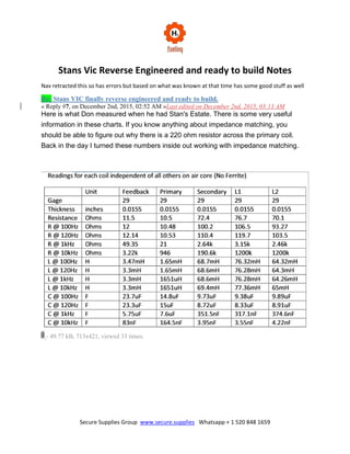
  • 1. Secure Supplies Group www.secure.supplies Whatsapp + 1 520 848 1659 Stans Vic Reverse Engineered and ready to build Notes Nav retracted this so has errors but based on what was known at that time has some good stuff as well Re: Stans VIC finally reverse engineered and ready to build. « Reply #7, on December 2nd, 2015, 02:52 AM »Last edited on December 2nd, 2015, 03:13 AM Here is what Don measured when he had Stan's Estate. There is some very useful information in these charts. If you know anything about impedance matching, you should be able to figure out why there is a 220 ohm resistor across the primary coil. Back in the day I turned these numbers inside out working with impedance matching. - 49.77 kB, 713x421, viewed 33 times.
  • 2. Secure Supplies Group www.secure.supplies Whatsapp + 1 520 848 1659 - 43.12 kB, 715x352, viewed 23 times.
  • 3. Secure Supplies Group www.secure.supplies Whatsapp + 1 520 848 1659 R.Walker Re: Stans VIC finally reverse engineered and ready to build. « Reply #8, on December 2nd, 2015, 03:06 AM » Thanks Ronnie. Very helpful information as usual. It made me giggle a little to see all those N/A readings at 10Khz in the 2nd and 4th charts. The resistance values in the first chart are more than interesting. Re: Stans VIC finally reverse engineered and ready to build. « Reply #9, on December 2nd, 2015, 03:15 AM » After working with these charts for over a year, it made me giggle to. R.Walker Re: Stans VIC finally reverse engineered and ready to build. « Reply #12, on December 2nd, 2015, 07:40 PM »Last edited on December 2nd, 2015, 07:45 PM No really it runs cool not warm at all. If you take Stan's primary which is 10.5 ohms when you do the math on impedance on the primary you will find that it needs to be 10 ohms. (10.5 and 220 ohms in parallel = 10 ohms) So placing a 220 ohm resistor across the primary it bring it right down to where it needs to be. Re: Stans VIC finally reverse engineered and ready to build. « Reply #13, on December 3rd, 2015, 04:23 AM »Last edited on December 3rd, 2015, 04:40 AM
  • 4. Secure Supplies Group www.secure.supplies Whatsapp + 1 520 848 1659 Nav, As you reverse engineer the VIC transformer I would like to give you a very important hint. At the same time, you must reverse engineer the CELL at the same time. If you don't, the reversed engineered VIC will be useless as you have seen in the past that everyone has tried to replicate. Keep this number (10) in the back of your mind at all times while you reading and doing your research. Stan used (10) Cells in series with his VIC for a very very important reason. No one will ever be able to scale the VIC and Cell up or down unless they stumble upon why (10) cells were used in series. Just keep (10) in your mind at all times, it is a very important number while you’re doing your impedance matching research. This is one of the most useful post I have ever posted, and will determine if you or anyone are successful or not. Re: Stans VIC finally reverse engineered and ready to build. « Reply #14, on December 3rd, 2015, 05:20 AM » You mean the capacitive reactance must match the inductive reactance? Re: Stans VIC finally reverse engineered and ready to build. « Reply #15, on December 3rd, 2015, 05:44 AM »Last edited on December 3rd, 2015, 05:50 AM I can't elaborate no more than I have already. But all the information Stan gives us with his formulas and the statement he uses (anyone with the knowledge of the prior art). When I was a Ham Radio operator back in my younger days little did, I know I was teaching myself about the prior art of all this. The prior art is all about getting every ounce of power out the load and no power reflected back. Re: Stans VIC finally reverse engineered and ready to build. « Reply #16, on December 3rd, 2015, 06:08 AM »Last edited on December 3rd, 2015, 06:14 AM Gps, reflection and standing waves only work with AC to the cell. And capacitive area of the cell must be symmetric for that. Skin effect in the cell must be taken into account. Re: Stans VIC finally reverse engineered and ready to build. « Reply #17, on December 3rd, 2015, 06:48 AM »Last edited on December 3rd, 2015, 07:50 AM Maybe a better term to use other than power reflected back would be power loss to the cell no matter how it is lost. (Unwanted resistance) That was the point I was trying to get across. It won’t do anyone any good to make voltage with any transformer if the cell never sees it and use it. Just a waste to create something that is destroyed before any use can be gotten out of it. Re: Stans VIC finally reverse engineered and ready to build. « Reply #18, on December 3rd, 2015, 07:50 AM »
  • 5. Secure Supplies Group www.secure.supplies Whatsapp + 1 520 848 1659 If the inductive reactance can be changed with frequency, pulse width and voltage amplitude, if either parameter changes you must change the capacitive reactance to match or there will be no impedance match. Re: Stans VIC finally reverse engineered and ready to build. « Reply #20, on December 3rd, 2015, 08:02 AM »Last edited on December 3rd, 2015, 08:09 AM Very true Nav, but once you achieve matching the inductive reactance and the capacitive reactance there is still resistance in the coils of wire that you don't want. So therefore, you will never truly impedance match the line with the load without removing that resistance too. Question is, how do you do it? You will have to do your research on this all on your own. I must keep to my promise and I have pushed myself up to the line on it. Re: Stans VIC finally reverse engineered and ready to build. « Reply #21, on December 3rd, 2015, 08:05 AM »Last edited on December 3rd, 2015, 08:46 AM Believe me if it all was about ohms law, everyone would be building ohms law machines. LMAO All I can say about applying ohms law to Stan's Vic and cell, you better know how to at least know how to control every aspect of ohms law first. For if you don't it will control you and all you will see is Amps Amps and more Amps just like Max Miller. Re: Stans VIC finally reverse engineered and ready to build. « Reply #25, on December 3rd, 2015, 09:08 AM »Last edited on December 3rd, 2015, 10:06 AM What I am saying is there is nothing about Stan's Vic or Cell that is fixed in value, it is all variable with the right knowledge. It all can be controlled, to output the most power to the cell and its only limitations is that of the design of it all. The more design flaws you have in it the less power you have to the cell; the less power you have the less gas you will be able to create (If any gas at all.) But with the right design it can be scaled up or down from Stan's Vic and number of cells. But you are correct in what you’re saying but when you have chokes involved on both sides of the secondary things start to get messy really quick as far as the cell goes. I'm not getting into the different frequencies of the coils and harmonics of them, Nav has done a wonderful job explaining all that in his post. All I am trying to say is you have to get rid of all coil resistance of the wire also in order to truly impedance match the secondary side to the cell, canceling out the inductors and capacitors at the right frequency won’t cut it. There is still resistance in the wire of the coils that has to be dealt with. In Stan's Vic you have 3 coils of wire that has 70 ohms or more in each one of them and also 1 that has 11 ohms all on the secondary side. Question is what are you going to do with all that resistance that is in the wire? Frequency and Duty cycle will never get rid of it. So what method are you going to use to deal with it to match it to the cells? The answer is hidden in the number (10).
  • 6. Secure Supplies Group www.secure.supplies Whatsapp + 1 520 848 1659 Re: Stans VIC finally reverse engineered and ready to build. « Reply #31, on December 3rd, 2015, 06:13 PM »Last edited on December 3rd, 2015, 06:26 PM Nav, since we are talking about VIC's in this thread, let's compare VIC's of two different types Stan used. Why not compare the copper VIC that is used for the 11 cavity cell to the Stainless steel wire VIC used for the water spark plug. It may lead you to some answers your looking for. Question is, Why is there less resistance in the copper VIC for the 11 cavity cell? and more resistance in the stainless steel Vic for one spark plug cell? I would like to see what people’s opinion is on this. Should lead to a pretty good discussion. would like to see what people’s opinion is on this. Should lead to a pretty good discussion. Re: Stans VIC finally reverse engineered and ready to build. « Reply #32, on December 4th, 2015, 04:50 AM »Last edited on December 4th, 2015, 06:49 AM Copper is more conductive and less resistive than steel. So when building a small spark plug cell you need to match the resistance of the small stainless plug which means using less conductive more resistive stainless steel wire. In the 11 cell array the total amount of stainless steel used and its resistance value would need to match the resistance of the copper cell. Therefore, if you have 230 Ohms between the three coils on the VIC and your primary is 10 Ohms you would need a 220 Ohm resistor across the primary so when the primary is switched back on you balance that figure. When you are building your cell in series tubes, the total resistance of the cell would be 230 Ohms for a 10 cell array, that’s 23 Ohms per tube set. However, when building in parallel it’s a different calculation and if you built a six tube array each tube pair would need to be 1400 Ohms in free space to match 230 Ohms. Therefore it would be easier to work in sets of ten tube arrays because of the resistance difference between stainless steel and copper. It’s easier to calculate and build. So if you have a 238 Ohms across the three coils in the VIC, all you have to do is multiply it by 10 in each tube pair so each pair of tubes would be 2380 Ohms. To scale it down you go in series instead of parallel and change the resistance of the coil wire. Re: Stans VIC finally reverse engineered and ready to build. « Reply #33, on December 4th, 2015, 08:11 AM » Those reactive inductance values on a ferrite core that are missing for 10Khz are important because I can match the 1.2 million ohms of the free space model in my capacitive reactance with a 1000mm2 plates but to match my plates in a ferrite core I need the reactive inductance value in a ferrite core to set the plate size value.
  • 7. Secure Supplies Group www.secure.supplies Whatsapp + 1 520 848 1659 Re: Stans VIC finally reverse engineered and ready to build. « Reply #34, on December 4th, 2015, 09:59 AM » Here is a question worth its weight in gold. The chart below shows the resistance of the secondary and the two chokes in free space on their own and they are all in the 70's of Ohms. But when they are pulsed at 10Khz in the circuit the two chokes have a massive 1.2 million Ohms impedance each yet the secondary is 190,000 Ohms. Who is smart enough to know why? The answer reinforces something I said recently. Re: Stans VIC finally reverse engineered and ready to build. « Reply #38, on December 4th, 2015, 11:20 AM » Quote from Lynx on December 4th, 2015, 10:54 AM Well, normally I wouldn't get into details in such a thread like this, but since you're asking I couldn't help but noticing that by using the given numbers in the chart I can't really understand the given results in the chart for the individual coils at hand and by that I mean by using the school book formula for calculating inductive reactance, XL = 2 * PI * F * L, the numbers don't add up to match those found in the chart for the given frequencies at hand. On the other hand it does say R @ [frequency], not XL @ [frequency] , so maybe I just don't get it, I'll buy that.
  • 8. Secure Supplies Group www.secure.supplies Whatsapp + 1 520 848 1659 Also, if I understand it correctly each coil were separately pulsed, I.E they were not connected to any other coil as they were pulsed, while also not being on any core of any sort, only air, right? If it's easier to explain all this by showing me a document that which explains all this = feel free to point me there. Look at the coil’s reactance @ 10Khz compared to other frequencies. Most frequencies, each coil has the same ball park figure but @ 10Khz the two chokes become highly reactive towards each other and the impedance is an exact match even though the coils are not evenly wound and have different static resistance. That mismatch shows up somewhere else but not in the chokes and I have measured it many times. It’s called bias and is transferred to something else that is willing to except it. Re: Stans VIC finally reverse engineered and ready to build. « Reply #45, on December 4th, 2015, 02:47 PM »Last edited on December 4th, 2015, 03:02 PM One thing I can help with is the dielectric. Stan shows many many times that is 78.54 ohms in natural water. It can range anywhere from 70 to 80 depending on the water and Temp. Read the Tech Brief, it is referenced at least 5 or 6 times not including other documents and patents. Re: Stans VIC finally reverse engineered and ready to build. « Reply #49, on December 5th, 2015, 05:54 AM »Last edited on December 5th, 2015, 06:04 AM The mathematics work perfectly in those charts. From those charts I have worked out that the inductive reactance @ 10Khz needs to be 1.02 million Ohms. Its capacitive reactance is 15.6pf 1. Flat plates: @10Khz If you have a flat plate 24.2 x 24.2 mm2, a gap of 1mm its inductive reactance is 1.02 million Ohms @ 15.6pf in the plates. 2, Tubes: @10Khz If you have a pair of tubes 16 inches long then you have 29,450mm2 of surface area per tube set, a gap of 5mm, and 156.6 pf per tube set. This is divided by 10 in a series calculation of 10 tube sets and is 15.6pf and 1.02 million ohms for the entire tube set. The math’s is perfect if you know what you're looking at. If you don't know what you’re looking at none of it will make sense and you won't be able to scale any of it down to a spark plug sized cell. Re: Stans VIC finally reverse engineered and ready to build. « Reply #50, on December 5th, 2015, 06:42 AM »Last edited on December 5th, 2015, 06:49 AM
  • 9. Secure Supplies Group www.secure.supplies Whatsapp + 1 520 848 1659 Here are several references from the TECH BRIEF and there is many many more from other documents of the Re of water. Re is used in all his formulas to get the total Z impedance. So how can you not use the Re that he gives us to calculate the Z? Reference shows that the Re of the water is a dielectric constant of 78.54 and also shows it in ohms.
  • 10. Secure Supplies Group www.secure.supplies Whatsapp + 1 520 848 1659
  • 11. Secure Supplies Group www.secure.supplies Whatsapp + 1 520 848 1659 Re: Stans VIC finally reverse engineered and ready to build. « Reply #51, on December 5th, 2015, 06:58 AM »Last edited on December 5th, 2015, 07:01 AM Take note of the opposite windings on the lower schematic, when differential mode current passes through this core, it cancels the magnetic flux fields. The reference to 78 Ohms is the resistive value that water presents when trying to pass current @ 5Khz and is no reference to self resonance @ 10Khz. Re: WATER FUEL CELL Technical Brief (Building, Testing and Understanding Stan's Work) « Reply #1777, on December 22nd, 2014, 08:00 AM »Last edited on December Design a transformer that will enable the maximum power to be transferred to your head phones. voltage transformation ratio = Nsec/Nprim current transformer ratio =Nprim/Nsec Impedance transformation ratio = (Nsec/Nprim)^2 Inductance ratio = (Nsec/Nprim)^2 Where N=number of turns in winding ANSWER: You know from equation (Rint=Rl ) that maximum power transfer occurs when Reff= Rint =20ohm. You also know from equation [ Reff = (Np/N2)^2 Rl and r=Np/Ns) ] that the effective resistance seen by the power supply is Reff= r^2 x RL= r^2 x 2000ohms . Combining these two equations yields 20ohms=Reff= r^2 x 2000ohms so solving for r we obtain r^2= 20ohms/2000ohms =1/100 and r=1/10 is the turns ratio. Translating this to the VIC: Secondary+choke1+choke2 = (72.4 + 76.7 + 70.1) = 219.2ohms Primary=10.5ohms (219.2:10.5) impedance transformation ratio 219.2/10.5 = 20.87 [NOTE. Meyer has this 30:1 stated in his patent ] sqrt(20.87) (4.569:1) winding ratio If I try as example 537 wnd on the primary coil is 10.5ohms we need 537 x 4.569 = 2453wnd on the secondary for maximum power transfer at the load.
  • 12. Secure Supplies Group www.secure.supplies Whatsapp + 1 520 848 1659 Mr.Walker, can you say how this translates to the multiple coils (chokes) ? The water resistance makes part of the circuit, this mean we also add the Re to the total coils resistance? Let’s say Re=1972ohms as example. Re: WATER FUEL CELL Technical Brief (Building, Testing and Understanding Stan's Work) « Reply #1780, on December 22nd, 2014, 05:42 PM »Last edited on December 22nd, 2014, 08:48 PM @ Webmug, When you add the total Z which you have at 219.2 ohms 220 just to round numbers excluding the Re of the water. Now you are saying the resistance of your water is 1972 ohms. Stan does not want the (R) resistance of the water, He is wanting the (Re) of the water. The Re of the water can be anywhere from 70 to 80 which is the Dielectric Constant of water. Stan say's the Re is 78.54 at 25C. Now let's add 220 total coil resistance, and 80 Re dielectric of water. Now we have the total Z which is 300. We now can divide 300/10.5 which = 28.57 so we have a 28.57/1 ratio. Odd ratio, now how do we fix this odd ratio. Simple just like Stan did........put a 220 ohm resistor across the primary.... Now we have a 220 ohm resistor in parallel with a 10.5 ohm coil.... Now what does this give us? It changes the 10.5 ohms in the primary to 10 ohms. Now we have 300/10 which equals 30:1 ratio. There you go now you have another piece of the mystery. You could have found this information at http://app.hydrofuel.ca Webmug when you get everything worked out you will see why you cannot use 1 cell to get this to work. There is no way because the capacitance is too high in the cell. Just keep working it out and you will see what I am talking about...Your doing a great Job as I have said before. Keep it up and don't give up, you have come to far. Re: Stans VIC finally reverse engineered and ready to build. « Reply #13, on December 3rd, 2015, 04:23 AM »Last edited on December 3rd, 2015, 04:40 AM Nav, as you reverse engineer the VIC transformer, I would like to give you a very important hint. At the same time, you must reverse engineer the CELL at the same time. If you don't, the reversed engineered VIC will be useless as you have seen in the past that everyone has tried to replicate. Keep this number (10) in the back of your mind at all times while you’re reading and doing your research. Stan used (10) Cells in series with his VIC for a very very important reason. No one will ever be able to scale the VIC and Cell up or down unless they stumble upon why (10) cells were used in series. Just keep (10) in your mind at all times, it is a very important number while you’re doing your
  • 13. Secure Supplies Group www.secure.supplies Whatsapp + 1 520 848 1659 impedance matching research. This is one of the most useful post I have ever posted, and will determine if you or anyone are successful or not. R.Walker Re: Stans VIC finally reverse engineered and ready to build. « Reply #14, on December 3rd, 2015, 05:20 AM » You mean the capacitive reactance must match the inductive reactance? Re: Stans VIC finally reverse engineered and ready to build. « Reply #15, on December 3rd, 2015, 05:44 AM »Last edited on December 3rd, 2015, 05:50 AM I can't elaborate no more than I have already. But all the information Stan gives us with his formulas and the statement he uses (anyone with the knowledge of the prior art). When I was a Ham Radio operator back in my younger days little did, I know I was teaching myself about the prior art of all this. The prior art is all about getting every ounce of power out the load and no power reflected back. R.Walker Re: Stans VIC finally reverse engineered and ready to build. « Reply #16, on December 3rd, 2015, 06:08 AM »Last edited on December 3rd, 2015, 06:14 AM Gps, reflection and standing waves only work with AC to the cell. And capacitive area of the cell must be symmetric for that. Skin effect in the cell must be taken into account. Re: Stans VIC finally reverse engineered and ready to build. « Reply #17, on December 3rd, 2015, 06:48 AM »Last edited on December 3rd, 2015, 07:50 AM Maybe a better term to use other than power reflected back would be power loss to the cell no matter how it is lost. (Unwanted resistance) That was the point I was trying to get across. It won’t do anyone any good to make voltage with any transformer if the cell never sees it and use it. Just a waste to create something that is destroyed before any use can be gotten out of it. R.Walker Re: Stans VIC finally reverse engineered and ready to build. « Reply #18, on December 3rd, 2015, 07:50 AM »
  • 14. Secure Supplies Group www.secure.supplies Whatsapp + 1 520 848 1659 If the inductive reactance can be changed with frequency, pulse width and voltage amplitude, if either parameter changes you must change the capacitive reactance to match or there will be no impedance match. Re: Stans VIC finally reverse engineered and ready to build. « Reply #20, on December 3rd, 2015, 08:02 AM »Last edited on December 3rd, 2015, 08:09 AM Very true Nav, but once you achieve matching the inductive reactance and the capacitive reactance there is still resistance in the coils of wire that you don't want. So therefore, you will never truly impedance match the line with the load without removing that resistance too. Question is, how do you do it? You will have to do your research on this all on your own. I must keep to my promise and I have pushed myself up to the line on it. Believe me if it all was about ohms law, everyone would be building ohms law machines. LMAO All I can say about applying ohms law to Stan's Vic and cell, you better know how to at least know how to control every aspect of ohms law first. For if you don't it will control you and all you will see is Amps Amps and more Amps just like Max Miller. Re: Stans VIC finally reverse engineered and ready to build. « Reply #25, on December 3rd, 2015, 09:08 AM »Last edited on December 3rd, 2015, 10:06 AM What I am saying is there is nothing about Stan's Vic or Cell that is fixed in value, it is all variable with the right knowledge. It all can be controlled, to output the most power to the cell and its only limitations is that of the design of it all. The more design flaws you have in it the less power you have to the cell; the less power you have the less gas you will be able to create (If any gas at all.) But with the right design it can be scaled up or down from Stan's Vic and number of cells. But you are correct in what you’re saying but when you have chokes involved on both sides of the secondary things start to get messy really quick as far as the cell goes. I'm not getting into the different frequencies of the coils and harmonics of them, Nav has done a wonderful job explaining all that in his post. All I am trying to say is you have to get rid of all coil resistance of the wire also in order to truly impedance match the secondary side to the cell, canceling out the inductors and capacitors at the right frequency won’t cut it. There is still resistance in the wire of the coils that has to be dealt with. In Stan's Vic you have 3 coils of wire that has 70 ohms or more in each one of them and also 1 that has 11 ohms all on the secondary side. Question is what are you going to do with all that resistance that is in the wire? Frequency and Duty cycle will never get rid of it. So what method are you going to use to deal with it to match it to the cells? The answer is hidden in the number (10). Re: Stans VIC finally reverse engineered and ready to build.
  • 15. Secure Supplies Group www.secure.supplies Whatsapp + 1 520 848 1659 « Reply #26, on December 3rd, 2015, 09:47 AM »Last edited on December 3rd, 2015, 09:57 AM Where magnetic vectors are cancelled, the voltage field is 90 degrees out of phase to the linear inductance. So the resistance of the coil is no longer a linear value. You would need to measure the coil at very low voltage first and establish its electrostatic inductance as a resistance value then match the capacitive reactance in the tubing of the cell. As you go up in voltage steps keep matching the cell's reactance to the changing resistance value. When the coil goes up in distributed capacitance, the distributed inductance rises square to voltage and its resistance value changes. Therefore, its PEAK resistance must be matched in the cell not its free space resistance. Re: Stans VIC finally reverse engineered and ready to build. « Reply #27, on December 3rd, 2015, 11:27 AM »Last edited on December 3rd, 2015, 01:04 PM Ronnie, are you saying that when you charge the secondary and the chokes, after the primary is shut off and resonance takes place when resonance has finished and the primary is switched back on, the primary will be confronted with the combined left over resistance from the static inductance field and you need to cancel that resistance with a primary match? Re: Stans VIC finally reverse engineered and ready to build. « Reply #31, on December 3rd, 2015, 06:13 PM »Last edited on December 3rd, 2015, 06:26 PM Nav, since we are talking about VIC's in this thread, let's compare VIC's of two different types Stan used. Why not compare the copper VIC that is used for the 11 cavity cell to the Stainless steel wire VIC used for the water spark plug. It may lead you to some answers your looking for. Question is, Why is there less resistance in the copper VIC for the 11 cavity cell? and more resistance in the stainless steel Vic for one spark plug cell? I would like to see what people’s opinion is on this. Should lead to a pretty good discussion. Re: Stans VIC finally reverse engineered and ready to build. « Reply #32, on December 4th, 2015, 04:50 AM »Last edited on December 4th, 2015, 06:49 AM Quote from gpssonar on December 3rd, 2015, 06:13 PM Nav, since we are talking about VIC's in this thread, let's compare VIC's of two different types Stan used.
  • 16. Secure Supplies Group www.secure.supplies Whatsapp + 1 520 848 1659 Why not compare the copper VIC that is used for the 11 cavity cell to the Stainless steel wire VIC used for the water spark plug. It may lead you to some answers your looking for. Question is, Why is there less resistance in the copper VIC for the 11 cavity cell? and more resistance in the stainless steel Vic for one spark plug cell? I would like to see what people’s opinion is on this. Should lead to a pretty good discussion. Copper is more conductive and less resistive than steel. So when building a small spark plug cell you need to match the resistance of the small stainless plug which means using less conductive more resistive stainless steel wire. In the 11 cell array the total amount of stainless steel used and its resistance value would need to match the resistance of the copper cell. Posted: December 4th, 2015, 04:09 AM Therefore, if you have 230 Ohms between the three coils on the VIC and your primary is 10 Ohms you would need a 220 Ohm resistor across the primary so when the primary is switched back on you balance that figure. When you are building your cell in series tubes, the total resistance of the cell would be 230 Ohms for a 10 cell array, thats 23 Ohms per tube set. However, when building in parallel it’s a different calculation and if you built a six tube array each tube pair would need to be 1400 Ohms in free space to match 230 Ohms. Therefore it would be easier to work in sets of ten tube arrays because of the resistance difference between stainless steel and copper. It’s easier to calculate and build. So if you have a 238 Ohms across the three coils in the VIC, all you have to do is multiply it by 10 in each tube pair so each pair of tubes would be 2380 Ohms. To scale it down you go in series instead of parallel and change the resistance of the coil wire. Re: Stans VIC finally reverse engineered and ready to build. « Reply #33, on December 4th, 2015, 08:11 AM » Those reactive inductance values on a ferrite core that are missing for 10Khz are important because I can match the 1.2 million ohms of the free space model in my capacitive reactance with a 1000mm2 plates but to match my plates in a ferrite core I need the reactive inductance value in a ferrite core to set the plate size value. Re: Stans VIC finally reverse engineered and ready to build. « Reply #34, on December 4th, 2015, 09:59 AM »
  • 17. Secure Supplies Group www.secure.supplies Whatsapp + 1 520 848 1659 Here is a question worth its weight in gold. The chart below shows the resistance of the secondary and the two chokes in free space on their own and they are all in the 70's of Ohms. But when they are pulsed at 10Khz in the circuit the two chokes have a massive 1.2 million Ohms impedance each yet the secondary is 190,000 Ohms. Who is smart enough to know why? The answer reinforces something I said recently. Re: Stans VIC finally reverse engineered and ready to build. « Reply #38, on December 4th, 2015, 11:20 AM » Quote from Lynx on December 4th, 2015, 10:54 AM Well, normally I wouldn't get into details in such a thread like this, but since you're asking I couldn't help but noticing that by using the given numbers in the chart I can't really understand the given results in the chart for the individual coils at hand and by that I mean by using the school book formula for calculating inductive reactance, XL = 2 * PI * F * L, the numbers don't add up to match those found in the chart for the given frequencies at hand. On the other hand it does say R @ [frequency], not XL @ [frequency] , so maybe I just don't get it, I'll buy that.
  • 18. Secure Supplies Group www.secure.supplies Whatsapp + 1 520 848 1659 Also, if I understand it correctly each coil were separately pulsed, I.E they were not connected to any other coil as they were pulsed, while also not being on any core of any sort, only air, right? If it's easier to explain all this by showing me a document that which explains all this = feel free to point me there. Look at the coils reactance @ 10Khz compared to other frequencies. Most frequencies, each coil has the same ball park figure but @ 10Khz the two chokes become highly reactive towards each other and the impedance is an exact match even though the coils are not evenly wound and have different static resistance. That mismatch shows up somewhere else but not in the chokes and I have measured it many times. It’s called bias and is transferred to something else that is willing to except it. Re: Stans VIC finally reverse engineered and ready to build. « Reply #43, on December 4th, 2015, 02:25 PM » Quote from Ris on December 4th, 2015, 02:16 PM Like Lynx said reactance numbers do not match to the frequency, away off. It depends what dielectric constant you use in the equation Re: Stans VIC finally reverse engineered and ready to build. « Reply #45, on December 4th, 2015, 02:47 PM »Last edited on December 4th, 2015, 03:02 PM Yes, but not to be shared at this point in time. Several of them. Sorry guy's that I can't be more active in the discussion, My Wife's mother is in ICU with several strokes all at once. Not looking good for her. Maybe I can be of more help later. One thing I can help with is the dielectric. Stan shows many many times that is 78.54 ohms in natural water. It can range anywhere from 70 to 80 depending on the water and Temp. Read the Tech Brief, it is referenced at least 5 or 6 times not including other documents and patents. Re: Stans VIC finally reverse engineered and ready to build. « Reply #49, on December 5th, 2015, 05:54 AM »Last edited on December 5th, 2015, 06:04 AM The mathematics work perfectly in those charts. From those charts I have worked out that the inductive reactance @ 10Khz needs to be 1.02 million Ohms. Its capacitive reactance is 15.6pf 1. Flat plates: @10Khz If you have a flat plate 24.2 x 24.2 mm2, a gap of 1mm its inductive reactance is 1.02 million Ohms @ 15.6pf in the plates. 2, Tubes: @10Khz
  • 19. Secure Supplies Group www.secure.supplies Whatsapp + 1 520 848 1659 If you have a pair of tubes 16 inches long then you have 29,450mm2 of surface area per tube set, a gap of 5mm, and 156.6 pf per tube set. This is divided by 10 in a series calculation of 10 tube sets and is 15.6pf and 1.02 million ohms for the entire tube set. The math’s is perfect if you know what you're looking at. If you don't know what you’re looking at none of it will make sense and you won't be able to scale any of it down to a spark plug sized cell. Re: Stans VIC finally reverse engineered and ready to build. « Reply #50, on December 5th, 2015, 06:42 AM »Last edited on December 5th, 2015, 06:49 AM Here are several references from the TECH BRIEF and there are many many more from other documents of the Re of water. Re is used in all his formulas to get the total Z impedance. So how can you not use the Re that he gives us to calculate the Z? Reference shows that the Re of the water is a dielectric constant of 78.54 and also shows it in ohms.
  • 20. Secure Supplies Group www.secure.supplies Whatsapp + 1 520 848 1659
  • 21. Secure Supplies Group www.secure.supplies Whatsapp + 1 520 848 1659
  • 22. Secure Supplies Group www.secure.supplies Whatsapp + 1 520 848 1659 Re: Stans VIC finally reverse engineered and ready to build. « Reply #51, on December 5th, 2015, 06:58 AM »Last edited on December 5th, 2015, 07:01 AM Take note of the opposite windings on the lower schematic, when differential mode current passes through this core, it cancels the magnetic flux fields. The reference to 78 Ohms is the resistive value that water presents when trying to pass current @ 5Khz and is no reference to self resonance @ 10Khz. Re: Stans VIC finally reverse engineered and ready to build. « Reply #54, on December 5th, 2015, 08:01 AM »Last edited on December 5th, 2015, 08:36 AM What is the Total Z of this circuit using Stan's formulas? You can work out the Z value of the L1 and L2 along with the capacitance value from the chart below and the formulas from the Tech Brief Eq 1,8,9. This will be with air core values. I would like to see everyone's answer; this could show how everyone has a different answer. Also notice where the #(10) shows up.
  • 23. Secure Supplies Group www.secure.supplies Whatsapp + 1 520 848 1659 Re: Stans VIC finally reverse engineered and ready to build. « Reply #57, on December 5th, 2015, 08:38 AM » Quote from resonance1 on December 5th, 2015, 08:33 AM Thank you gpssonar, I don't agree that distilled water has a resistive value of 78ohms, that's its dielectric constant, pure distilled water is an insulator with very high ohmic value, you showed me where the ohmic value for distilled water came from, been scratching my head about that for a while, its much appreciated that you cleared that up. The reason I cannot use 78ohms resistance in place of a dielectric constant of 78 is dielectric constant and its resultant ability to hold charge is not an ohmic value, it makes no sense to me at this time, capacitors don't have resistive values they have capacitive reactance values @ a given frequency which is derived from their capacitance calculated from plate area and spacing plus the dielectric constant of the dielectric between them,
  • 24. Secure Supplies Group www.secure.supplies Whatsapp + 1 520 848 1659 the paper only makes sense if you remove ohms from the 78 so I'm lost unless somebody can explain this new law of physics. Thanks again. Because the circuit has two values, one @ resonance which is capacitive and one @ non resonance which is resistive. Re: Stans VIC finally reverse engineered and ready to build. « Reply #59, on December 5th, 2015, 08:52 AM » total Z =230+785 I would add an additional 10 for the primary Re: Stans VIC finally reverse engineered and ready to build. « Reply #60, on December 5th, 2015, 09:00 AM »Last edited on December 5th, 2015, 09:30 AM Allan(Rav) and I fumbled with the dielectric constant of the water being 78.54 ohms the same way most people are doing also when we were doing our own research on it. I showed references in the post above and like I said they are many more in other documents of his. You can only can come to a conclusion he is not telling the truth, or people don't yet understand how he comes up with it being 78.54 ohms. Re: Stans VIC finally reverse engineered and ready to build. « Reply #62, on December 5th, 2015, 09:32 AM »Last edited on December 5th, 2015, 10:01 AM Good number for hydrogen and oxygen as the dielectric, I would think. Re: Stans VIC finally reverse engineered and ready to build. « Reply #62, on December 5th, 2015, 09:32 AM »Last edited on December 5th, 2015, 10:01 AM Good number for hydrogen and oxygen as the dielectric, I would think. Note: Else where has state should tune tub in air so this make great sense! Re: Stans VIC finally reverse engineered and ready to build. « Reply #65, on December 5th, 2015, 10:02 AM »Last edited on December 5th, 2015, 10:17 AM Quote from resonance1 on December 5th, 2015, 09:51 AM I don't think Stan is telling lies at this point but likely misusing the term ohms as a dielectric constant, it seems obvious that when the cell is producing lots of gas the dielectric value will be much
  • 25. Secure Supplies Group www.secure.supplies Whatsapp + 1 520 848 1659 lower than when the cell is only full of water, Stan tells us it changes with gas production in his talk but not in which direction it changes, I could be wrong but that's how it looks to me. Good post. Guy's I am going to throw this out there to you all for what's it worth. Water is not going to be the dielectric in the cell forever. And It looks like a couple of you are catching on now. My deed is done. Re: Stans VIC finally reverse engineered and ready to build. « Reply #66, on December 5th, 2015, 10:05 AM »Last edited on December 5th, 2015, 10:09 AM Quote from nav on December 5th, 2015, 09:56 AM 3 sounds an excellent number lynx for water that has turned to hydrogen and oxygen :P Good post also Nav, I stated this above your post. If you remember me saying, there is nothing that is of fixed value in the VIC or the CELL Re: Stans VIC finally reverse engineered and ready to build. « Reply #76, on December 6th, 2015, 04:00 AM » Ronnie you could start by telling people what the two holes are really doing on the VIC, you know the one between the two chokes and the one between the pickup and the secondary and what the 220 Ohm resistor really does when it sucks the primary dry and shuts the core down. Why the primary is sat directly over one of the holes where we cannot see the gap in the core?
  • 26. Secure Supplies Group www.secure.supplies Whatsapp + 1 520 848 1659 Re: Stans VIC finally reverse engineered and ready to build. « Reply #85, on December 6th, 2015, 07:17 AM »Last edited on December 6th, 2015, 08:23 AM Now back to the hole in the bobbins and the primary, anyone with common knowledge would know if you drilled a hole where the core material comes together would know that is an adjustment for the cores. Again, if you don't know what that adjustment does what are you fooling with this in the first place. As for you saying the primary is over the hole, no it's not the primary is the smallest coil, the feedback coil is over the hole. If your referencing my VIC Ii showed in my video yes, I use the feedback coil as my primary, it had nothing to do with it being over the hole. It was for testing purposes only because there were two wires wrapped together and I could see what the outcome would be if I only used one wire or tie them both together to see a result I wanted to see. I hope this has answered some questions and we can get back to the topic. And at any time if I am not welcome here in this thread or any other thread just let me know there will be no problem or hard feelings at all.
  • 27. Secure Supplies Group www.secure.supplies Whatsapp + 1 520 848 1659 Re: Stans VIC finally reverse engineered and ready to build. « Reply #103, on December 6th, 2015, 10:31 AM »Last edited on December 6th, 2015, 10:34 AM Re: Stans VIC finally reverse engineered and ready to build. « Reply #103, on December 6th, 2015, 10:31 AM » gpssonar, even with lots of impurities you will never get anything vaguely close to 78ohms unless you are talking about the capacitive reactance of the cell @ a given frequency, which is measured in ohms, that been imaginary ohms of capacitive reactance, Re: Stans VIC finally reverse engineered and ready to build. « Reply #105, on December 6th, 2015, 10:38 AM » Resonance, My first question to you is where have you ever seen that Stan used pure water (distilled)? Not that it can't be use. But in all the documents I have read he always talks about Natural water. As far as the 78.54 whether you use it in ohms or not. Use that number as the Re and you can't go wrong. Re: Stans VIC finally reverse engineered and ready to build. « Reply #113, on December 6th, 2015, 11:53 AM » you can wind them all same direction but can wire them in opposite direction. Re: Stans VIC finally reverse engineered and ready to build. « Reply #124, on December 6th, 2015, 05:50 PM »Last edited on December 6th, 2015, 06:51 PM @resonance1 This is just me saying, If I were doing a test on any type of water and I wanted to research what Stan meant by 78.54 ohms I would do a resistance test to the flow of amps in a cell like Stan's, I would use a cell like Stan's with the same gap and size of a cell and apply a power supply to it that had volts and amps on it, then I would apply a voltage at 1 volt 2 volt 3 volt and so on until I seen the first sign of one single bubble come out of the cell. Then I would notice the amp and voltage that I see that first bubble at. then I would calculate the amps and voltage to give me the resistance of where the reaction started taking place. I may even flood the cell with different levels of gas with higher voltages and see what that gives me also to see what it does to the resistance. I also may try and find where the voltage and amp in the cell equals 78.54 ohms and take notice what is taking place in the cell. There is some common sense solutions to try. Try it and see what you think. It's not about arguing, it's all about finding out why he uses 78.54 ohms as the Re in his formulas so many times in his document. Only research will put a stop to difference of opinions. I've did all this and more to find the answer. Re: Stans VIC finally reverse engineered and ready to build.
  • 28. Secure Supplies Group www.secure.supplies Whatsapp + 1 520 848 1659 « Reply #145, 24 months ago »Last edited 24 months ago Quote from nav on April 28th, 2017, 02:54 PM Stan says in the NZ video that the resonance changes as more bubbles in the cell effect the dielectric property but I don't think it will drop close to air because there is still a dielectric path around the bubbles, I would say it might drop to between 50 and 60 but not down to 2 or 3. If you use a capacitance calculator, a reactance calculator etc. then the calculations come out at impossible ranges but I guess we are dealing with unknowns so anything can happen. Well Nav, I agree that the capacitance wasn't also changing much. If the capacitance would drop down with 2 or 3 dielectric the choke LC is out of range. Stan had his 5 coiler VIC designed for natural rain water. So, the ppm didn't change too much (TB water table). All that changed could be tuned with the range of the scanner electronics.
  • 29. Secure Supplies Group www.secure.supplies Whatsapp + 1 520 848 1659 My conclusion is that the above impedance match is wrong!! Prove me wrong... ~webmug Re: Stans VIC finally reverse engineered and ready to build. « Reply #146, 24 months ago » Webmug I can't get any calculation anywhere near an LC circuit with the water gap at between 0.5mm and 1.5mm, a dielectric constant of 78-80 with the 5 coil VIC driving. The calculations are way out of range and so is the reactance. In spice, you can't decouple the chokes from the primary even 180 degrees out of phase, none of it computes.
  • 30. Secure Supplies Group www.secure.supplies Whatsapp + 1 520 848 1659 Anyway, going back to the New Zealand video I keep going on about Stan mentions the reason he chose 10-20khz was because it falls into the audio range and he could use audio transformers. There are no audio transformers with high impedance chokes on the core available, the chokes are stand alone and therefore decoupled from the primary so this afternoon I built an high impedance choke with two bifilars on my new ferrite core and i'm going to drive them with a 1:6 step up audio transformer. My new power supply has arrived, my pulse gen is on order and new oscilloscope is waiting for a factory re-stock before more are available. The choke has 100ohms of 30 gauge on each side making 4x50 ohm individual coils. It's going to be configured as a high impedance transmission line choke both sides driven by the audio transformer and are additive to the choke flux so i'm going to go for as much induction as I can get, possibly with air gaps. Re: Stans VIC finally reverse engineered and ready to build. « Reply #149, 24 months ago » The system will use current, Stan says magnetising his cores with the magnetising current for VICS and chokes will always use current and he mentions up to 3 amps in the NZ video. If this new choke core takes magnetising current from the secondary then so be it but what we don't want it to do is go beyond that magnetising current and hopefully the diode will take care of that, stopping the choke from current reversal. Re: Stans VIC finally reverse engineered and ready to build. « Reply #156, 24 months ago » the diode is used as a switch but not as a rectifier. so it could be decoupling component. Re: Stans VIC finally reverse engineered and ready to build. « Reply #158, 24 months ago »Last edited 24 months ago The system I'm building Matt has an oscillator which is the audio transformer and I'm passing the signal through a standalone choke. The choke is similar to an high pass filter and I'm asking the choke to cut off current that is of higher frequency/higher impedance than the oscillator, the diode half rectifies the signal from the transformer into an higher impedance, higher frequency signal which the choke absorbs as induction so it's perfectly understandable exactly what Stan was trying to do. But here lies an important factor: The current in the audio transformer lags the voltage by 90 degrees and the voltage has already begun to influence the choke before the current magnetizes the choke core which is what we want it to do. Then the signal is terminated by the audio transformer and therefore the choke is completely isolated from the input signal and decoupled from any primary. At this stage you've already won because you've only used
  • 31. Secure Supplies Group www.secure.supplies Whatsapp + 1 520 848 1659 primary current to magnetize two cores and nothing else, there is still no power factor involved but it doesn't finish there. The chokes magnetic field will still collapse in the opposing direction from which they were charged which is against the bias of the diode so current isn't a factor, but we still need to get the voltage from the choke into the series circuit and the WFC. The only direction is in the bias of the diode back through the secondary of the audio transformer and to do that you'd need to match the impedance of the choke with the cell. But here lies a great observation by Tesla and others: Even though the bias diode blocked the current from the choke reaching any primaries and therefore we have absolute decoupling going on, the choke can be made to resonate in an LC circuit and offload its voltage but a totally new phenomenon appears, the bias diode doubles the LC resonance yet again. Conclusions to this: If the audio transformer is running at 5khz then the high impedance, high frequency signal going into the choke is 10Khz because of the half rectification. Stan calls this a frequency doubler. The choke is inductive and suppresses the 10khz current from the transformer then tries to collapse in the opposite direction from which it was charged but the bias diode stops this, but then the energized choke forms an LC circuit with the cell BUT the diode doubles this frequency and that is why no calculations ever work out. The LC circuit when it is built MUST be resonant at TWICE the self-resonance of the choke not it's normal 10Khz self resonant frequency. The path through the secondary and the diode must be capable of resonating at 20Khz and this is why transformers cores are important, some people will have built the secondary core to take 10khz when in fact it needs to take 20khz. Another piece of the jigsaw is now in place. Tesla was a genius. Re: Stans VIC finally reverse engineered and ready to build. « Reply #160, 24 months ago » This is what occurs with an audio transformer and a standalone choke, the resonant LC circuit has to be 4 times higher frequency than the main pulse and appears during pulse off time in the 180 degrees of pulse off. You can see how this would fit into the 5 coil VIC but what you can't understand is how the chokes are decoupled from the primary flux. Unless in the 5 coil VIC the primary totally ignores the higher impedance in the core of course which means you would need a core that worked well at 5khz to energize it then performed badly at 20khz so that the primary became decoupled from the chokes/secondary at that frequency. Or you could have a VIC that didn't work at all at 5khz and you coupled the primary to the secondary with proximity, then the core becomes inductive at 10-20khz, do you see what I'm getting at guys?
  • 32. Secure Supplies Group www.secure.supplies Whatsapp + 1 520 848 1659 Re: Stans VIC finally reverse engineered and ready to build. « Reply #162, 18 months ago »Last edited 18 months ago Haven't posted in a while, I seen here where people are still struggling with the 78.54 ohms. The 78.54 ohms is the ohm value that is the Z Series resistance that is left over when you have a L value and and a C value in series at a resonate frequency. Example: If we have an inductor value of 1262.7 mH and a Capacitance value of 489 pF the resonate Frequency will be 6.40 kHz with a Z series resistance of 78.54 ohms Hope this helps with another piece of the puzzle to clear up the 78.54 ohms. Re: Stans VIC finally reverse engineered and ready to build. « Reply #164, 18 months ago » Quote from gpssonar on October 11th, 2017, 03:31 AM Haven't posted in a while, I seen here where people are still struggling with the 78.54 ohms. The 78.54 ohms is the ohm value that is the Z Series resistance that is left over when you have a L value and and a C value in series at a resonate frequency. This 78.54 ohms is only true when C happens to be a water capacitor correct?
  • 33. Secure Supplies Group www.secure.supplies Whatsapp + 1 520 848 1659 If C was say an air capacitor, then the left over value might be something like 300 ohms. Not exactly sure of that number, but I do recall hearing a number in that range for the impedance of free space. Re: Stans VIC finally reverse engineered and ready to build. « Reply #165, 18 months ago »Last edited 18 months ago Matt it can hold true to any capacitor and the dielectric your trying to tune into. (Air for example). But as Stan stated you are tuning into the properties of water which he calls 78.54 ohms. I gave an example of a value of an inductor and capacitor in series that will give you the resistance of the properties of water. If you change any value of the inductor or capacitor you will see how hard it is to find that value. You will also see why people are chasing the frequency all over the place and accomplishing little to no results. Again it's all a tunned circuit of resonance. Re: Stans VIC finally reverse engineered and ready to build. « Reply #166, 18 months ago »Last edited 18 months ago I'm beginning to understand. There seems to be a sweet spot with resonant circuits. Still unable to put my finger on it exactly. What I mean is: You can take any capacitor and any inductor, build a tank circuit and make it resonate at some frequency, but there's more to the puzzle than that. In reality there is a most perfect capacitor and most perfect inductor for doing this. I started to discover this with Russ' cap-coil-cap transfer demonstration. Not any parts will work. You need a matched pair of caps and inductor. So, with Stan's system or any other resonant system for that matter, there should be two plots you can make--one for the inductor and another for the capacitor; where these two plots intersect should give you the exact components you need. Once I get my head wrapped around how to generate these plots, life should become much easier. My gut feeling is these plots are an overlay of the series and parallel resonance, since a tank circuit IS BOTH series and parallel simultaneously. Let me play with those values: Quote from gpssonar inductor value of 1262.7 mH Capacitance value of 489 pF resonate Frequency will be 6.40 kHz Z series resistance of 78.54 ohms
  • 34. Secure Supplies Group www.secure.supplies Whatsapp + 1 520 848 1659 And see if I can work this out on paper the way I think things have to be. And thank you Ronnie for sticking around. A little push now and then really does help a lot. Re: Stans VIC finally reverse engineered and ready to build. « Reply #179, 17 months ago » Quote from HHO-Dan on December 6th, 2017, 01:33 AM Hi Guys (GPS) Just a quick question. Since we now know the VIC only reaches resonance after most all of the water has left the cell is it safe to say at this point the VIC is functioning as the gas processor unit ? Thanks again ........Checking Xmas lights one at a time ......... The cell functions like the gas processor once the water turns to gas. Remember to Share as Much as you can if you are lazy and do not share reshare these docs pdfs than you can be sure they will disappear eventually DD