SlideShare a Scribd company logo
1 of 25
Radiometry and Photometry
Definition
Radiometry: The science of radiation measurement. The detection and
measurement of radiant energy, either as separate wavelengths or
integrated over a broad wavelength band, and the interaction of
radiation with matter in such ways as absorption, reflectance and
emission.
Photometry: The science of the measurement of light intensity, where
"light'' refers to the total integrated range of radiation to which the eye is
sensitive. It is distinguished from radiometry in which each separate
wavelength in the electromagnetic spectrum is detected and measured,
including the ultraviolet and infrared.
Radiometry and Photometry
F, Flux M, Flux/Proj. Area
I, Flux/W L,Flux/AWE, Flux/Area Rcd.
Radiant Flux
Watts
Luminous Flux
Lumens
Radiant Exitance
Watts/m2
Luminous Flux
Lumens/m2=Lux
A /
Radiance
Watts/m2/sr
Luminance
Lumens/m2/sr
1 Lambert=
(1L/cm2/sr)/p
1 ft Lambert = (1L/ft2/sr)/p
1m Lambert = (1L/m2/sr)/p
Radiant
Intensity
Watts/sr
Luminous
Intensity
Lumens/sr
1 Candela=1cd=1L/sr
W/
Irradiance
Watts/m2
Illuminance
Lumens/m2=
Lux
1 Ft Candle=1L/ft2
1 W is 685 L
at 555 nm.
Radiometric quantities
are related to photometric
quantities through the
CIE luminous efficiency
curve
Photometric unit = K() 
radiometric unit
Where K() = 685 V()
Radiometry and Photometry
Radiometric quantities
Radiometry is the science that allows us to answer “how much light is there?”
Quantity Symbol Units
Energy Q J
Power (flux) P, Φ W
Intensity I W / sr
Irradiance E W / m2
Exitance M W / m2
Radiance is the
most fundamental
radiometric quantity
Radiance W / (m2 sr)
“spectral” anything = per unit wavelength or frequency
ex. “spectral radiance” W / (m2 sr nm)
L
Q
t


P
W
P
A


2
P
A

 W
incident
exiting
CIE Luminous Efficiency Curve
Radiometric quantities are related
to photometric quantities through
the luminous efficiency curve.
The luminous flux corresponding
to 1W of radiant power at any
wavelength is given by the
product of 685lm and luminous
efficiency at the same
wavelength.
The Unit Solid Angle
One of the key concepts to understand the relationship between the
different photometric quantities is that of the solid angle, or
steradian. A steradian is defined as the solid angle which, from the
centre of a sphere, cuts off an area of the surface of that sphere equal
to the square of its radius. A full sphere therefore contains 4p
steradians.
The solid angle (W) in steradians is equal to the spherical surface
area (A) over which it is measured divided by the square of the
radius (r) at which it is measured.
W = A/r²
Radiant flux is a measure of how much radiometric power is being emitted by
a source. Flux, expressed in watts, is a measure of the rate of energy flow in
joules per second (J/s).
Luminous flux, on the other hand, is a measure of the power of visible light.
This measure depends on the sensitivity of the human eye and is therefore
based on the CIE Luminous Efficacy Curve for photopic conditions.
Thus the radiosity of any given light can be vastly different from its
luminosity depending on the spectral content of its emission, meaning that we
have to distinguish between the flow of energy (radiometric) and the flow of
light (photometric).
Radiant and Luminous Flux
Irradiance is a measure of radiometric flux per unit area, or flux density,
and is typically expressed in Watts per square meter (W/m²). It is
basically the amount of radiometric energy flowing in a particular
direction.
Illuminance, however, is a measure of photometric flux per unit area, or
visible flux density. Illuminance is typically expressed in lumens per
square meter (lux) or lumens per square foot (foot-candles).
Irradiance and Illuminance
Radiance is a measure of the flux density per unit solid viewing
angle, expressed in W/m²/Sr. Luminance is a measure of the
photometric brightness of a surface and is given in cd/m² or asb. As
such it is based on the amount of light being output or reflected off
surfaces in the environment. The human eye and the camera both
respond only to luminance.
Radiance and Luminance
Radiant Intensity is a measure of
radiometric power per unit solid angle,
expressed in watts per
steradian. Similarly, luminous
intensity is a measure of visible power
per solid angle, expressed in candela
(lumens per steradian).
Inverse Square Law
Radiant Intensity (I) is related to
irradiance (E) by the inverse square
law, as shown below:
I = E * r²
The flux leaving a point source within
any solid angle is distributed over
increasingly larger areas, producing an
irradiance that decreases with the
square of the distance
Radiant Intensity and luminous Intensity
Lambert's cosine law
Flux per unit solid angle leaving a surface in any direction is
proportional to the cosine of the angle between that direction
and the normal to the surface. A material that obeys Lambert's
cosine law is said to be an isotropic diffuser; it has the same
sterance (luminance, radiance) in all directions.
I() = I(0)cos (Lambert’s cosine law)
If the radiance at each angle is constant then
Le = I()/Acos()=I(0)cos()/Acos()= I(0) / A
Thus, when a radiating surface has a radiance that is
independent of the viewing angle, the surface is said to be
perfectly diffuse or a Lambertian surface.
Blackbody Radiation
 “Glowing red hot”--blackbody radiation is the name given to
electromagnetic radiation emitted by a heated object.
 Solids and dense gases give off blackbody radiation
 Thermal radiation spectrum range: 0.1 to 100 mm
 It includes some ultraviolet (UV) radiation and all visible (0.4-0.76
mm) and infrared radiation (IR).
Blackbody Radiation
 A blackbody is an ideal absorber: all radiation falling on a
blackbody, irrespective of wavelength or angle of incident, is
completely absorbed.
 A blackbody is also a perfect emitter: no body at the same
temperature can emit more radiation at any wavelength or
into any direction than a blackbody.
Blackbody Radiation
 Planck’s Law
 1900, Max Planck derived mathematical law describing distribution of
brightness in blackbody spectrum
 Stefan-Boltzmann Law
 Energy emission is greater at every wavelength as temperature increases;
total amount of radiant energy emitted increases with increasing temperature
 Wien’s Displacement Law
 Maximum emission found toward shorter wavelengths (blue end of
spectrum) as temperature increases
Radiation Laws
 Planck’s Law
The formula describing the spectral radiant emittance of a perfect blackbody
as a function of its temperature and the wavelength of the emitted radiation.
 Stefan-Boltzmann Law
The formula that indicates the total radiation at all wavelengths from a
perfect blackbody.
W Total = 5.67 x 10⁻¹² T 4(W/cm2)
 Wien’s Displacement Law
The formula that gives the wavelength of maximum spectral radiant
emittance of a perfect blackbody:
lmax = 2898/T(µm)









1
110745.3
/143885
8
T
e
M 

(W/m2-m)
Blackbody Radiation
 Radiation emitted by stars tends to
be much like that emitted by
blackbody
 Planck’s Law
 Stephan-Boltzmann Law
 Wien’s Displacement Law
Colour
 White light, or nearly white light from the Sun, contains a
continuous distribution of wavelengths.
 The light from the Sun is essentially that of a blackbody
radiator at 5780 K.
 The wavelengths (spectral colours) of white light can be
separated by a dispersive medium like a prism.
 Even more effective separation can be achieved with a
diffraction grating.
http://www.educypedia.be/education/physicsjavacolor.htm
Colour
Approximate model for sunlight:
 Assume the intensities for red (R), blue (B) and green (G)
are roughly equal.
 Also: Ignore its emissions in the colors orange, yellow,
and violet.
 We call the colours R, G, and B the primary additives.
Colour
 R, G, and B
Why are they the primary additives?
Because experiment shows:
Any perceived colour can be matched by an additive combination of
R, G and B.
Just choose appropriate relative intensities.
Reason: The eye has three types of sensors in the retina. They are each
sensitive to either R, G, or B light.
Note: One way we perceive white is when all primary colors enter the
eye in equal amounts.
Rules of colour mixing: additive
Additive Combining
You need to know these four facts:
R + G = Y (yellow).
R + B = M (magenta).
G + B = C (cyan).
R + G + B = W (white).
Important note:
We are combining light sources.
That is, each colour in the sum is entering our eye, simultaneously.
Rules of colour mixing: additive
Example: Colour TV
 Most TV tubes produce color as follows:
 Use three different phosphors on the screen, arranged in tiny dots.
 The three phosphors produce red, green or blue light, when struck
by the electron beam of the tube.
 The eye integrates the tiny dots to produce a mixture of the three
primaries.
 The three types produce red, green or blue light when an electron
beam impinges.
http://www.educypedia.be/education/physicsjavacolor.htm
Rules of colour mixing: subtractive
Subtractive combining
Subtractive colour mixing is the kind of mixing you get if you
illuminate colored filters with white light from behind
The commonly used subtractive primary colours are cyan,
magenta and yellow, and if you overlap all three in
effectively equal mixture, all the light is subtracted giving
black. Subtractive colour mixing is more complex than the
additive colour mixing you get with coloured spotlights.
Rules of colour mixing
http://www.educypedia.be/education/physicsjavacolor.htm
Subtractive Colour Mixing: Filters
Filters
 A filter absorbs light of certain colours. It lets
through the other colours.
 Example
 An ideal red filter absorbs all colours but red light. It
transmits red light.
 In the model W = R + G + B, the red filter absorbs
blue and green light, transmits red.
Subtractive Mixing Problems
 Two colors are mixed finely.
Or, two filters overlap.
 What is the resulting colour?
(Always assume white light is incident.)
http://www.educypedia.be/education/physicsjavacolor.htm
Exercise
1. We make a fine mixture of R and B paints. What color is
the mixture?
2. A yellow filter is put on an overhead projector above a
slit. What primary colours are absent? Why?
3. White light is incident on a pair of overlapping green and
red filters. What light emerges?
4. Mix cyan and yellow paint. What is the color of the
mixture?
http://www.educypedia.be/education/physicsjavacolor.htm

More Related Content

What's hot

Antireflection coatings
Antireflection coatingsAntireflection coatings
Antireflection coatings
ajay singh
 

What's hot (20)

Fermet's principle
Fermet's principleFermet's principle
Fermet's principle
 
Unit 6
Unit 6Unit 6
Unit 6
 
Diffraction of light
Diffraction of lightDiffraction of light
Diffraction of light
 
Cardinal Points
Cardinal PointsCardinal Points
Cardinal Points
 
Polarization and its Application
Polarization and its ApplicationPolarization and its Application
Polarization and its Application
 
Basics of Light, Refraction and Optics
Basics of Light, Refraction and OpticsBasics of Light, Refraction and Optics
Basics of Light, Refraction and Optics
 
polarization of light
polarization of lightpolarization of light
polarization of light
 
Cardinal points,thin lenses and thick lenses
Cardinal points,thin lenses and thick lensesCardinal points,thin lenses and thick lenses
Cardinal points,thin lenses and thick lenses
 
Optical fibers Theory and applications
Optical fibers Theory and applicationsOptical fibers Theory and applications
Optical fibers Theory and applications
 
Magnification
MagnificationMagnification
Magnification
 
OPTOMETRY –Part IV DIFFRACTION
OPTOMETRY –Part IV      DIFFRACTIONOPTOMETRY –Part IV      DIFFRACTION
OPTOMETRY –Part IV DIFFRACTION
 
Nd-YAG Laser | working and construction
Nd-YAG Laser | working and constructionNd-YAG Laser | working and construction
Nd-YAG Laser | working and construction
 
Aberrations
AberrationsAberrations
Aberrations
 
Stops pupils and ports
Stops pupils and portsStops pupils and ports
Stops pupils and ports
 
Polarization of Light and its Application (healthkura.com)
Polarization of Light and its Application (healthkura.com)Polarization of Light and its Application (healthkura.com)
Polarization of Light and its Application (healthkura.com)
 
Basic concept of laser physics
Basic concept of laser physicsBasic concept of laser physics
Basic concept of laser physics
 
Optical filters and its types
Optical filters and its types Optical filters and its types
Optical filters and its types
 
aberrations
aberrations aberrations
aberrations
 
Antireflection coatings
Antireflection coatingsAntireflection coatings
Antireflection coatings
 
Prism
Prism Prism
Prism
 

Viewers also liked

Photometry and interactions
Photometry and interactionsPhotometry and interactions
Photometry and interactions
Joni Albarico
 
Thermal radiation
Thermal radiationThermal radiation
Thermal radiation
Fungsam Lim
 
Coulometric method of analysis
Coulometric method of analysisCoulometric method of analysis
Coulometric method of analysis
Siham Abdallaha
 

Viewers also liked (18)

Radiometry and Photometry: LED Fundamentals
Radiometry and Photometry: LED FundamentalsRadiometry and Photometry: LED Fundamentals
Radiometry and Photometry: LED Fundamentals
 
L3 emr
L3 emrL3 emr
L3 emr
 
Photometry
PhotometryPhotometry
Photometry
 
Photometry and interactions
Photometry and interactionsPhotometry and interactions
Photometry and interactions
 
Photometry by Dr. Anurag Yadav
Photometry by Dr. Anurag YadavPhotometry by Dr. Anurag Yadav
Photometry by Dr. Anurag Yadav
 
Nephelometry, turbidometry & Reflectance photometry by Dr. Anurag Yadav
Nephelometry, turbidometry & Reflectance photometry by Dr. Anurag YadavNephelometry, turbidometry & Reflectance photometry by Dr. Anurag Yadav
Nephelometry, turbidometry & Reflectance photometry by Dr. Anurag Yadav
 
Optics part i
Optics   part iOptics   part i
Optics part i
 
CPTC Site Plan Review module 8.23.2015
CPTC Site Plan Review module 8.23.2015CPTC Site Plan Review module 8.23.2015
CPTC Site Plan Review module 8.23.2015
 
ASSA imaging group DSLR Photometry Talk 27 Nov 2015
ASSA imaging group DSLR Photometry Talk 27 Nov 2015ASSA imaging group DSLR Photometry Talk 27 Nov 2015
ASSA imaging group DSLR Photometry Talk 27 Nov 2015
 
A Novel Method to Improve Measurement Results of Flame Photometry Using Image...
A Novel Method to Improve Measurement Results of Flame Photometry Using Image...A Novel Method to Improve Measurement Results of Flame Photometry Using Image...
A Novel Method to Improve Measurement Results of Flame Photometry Using Image...
 
Thermal radiation
Thermal radiationThermal radiation
Thermal radiation
 
Luminaire Photometry External[1]
Luminaire Photometry External[1]Luminaire Photometry External[1]
Luminaire Photometry External[1]
 
Coulometric method of analysis
Coulometric method of analysisCoulometric method of analysis
Coulometric method of analysis
 
Thermal Radiation-I - Basic properties and Laws
Thermal Radiation-I - Basic properties and LawsThermal Radiation-I - Basic properties and Laws
Thermal Radiation-I - Basic properties and Laws
 
Chap16 Light
Chap16   LightChap16   Light
Chap16 Light
 
Illumination Lighting
Illumination LightingIllumination Lighting
Illumination Lighting
 
Flame photometry
Flame photometryFlame photometry
Flame photometry
 
INTERIOR LIGHTING DESIGN A STUDENT'S GUIDE
INTERIOR LIGHTING DESIGN A STUDENT'S GUIDEINTERIOR LIGHTING DESIGN A STUDENT'S GUIDE
INTERIOR LIGHTING DESIGN A STUDENT'S GUIDE
 

Similar to Chapter 1 radiometry_and_photometry

33-LIGHT-AND-ILLUMINATION.pptx
33-LIGHT-AND-ILLUMINATION.pptx33-LIGHT-AND-ILLUMINATION.pptx
33-LIGHT-AND-ILLUMINATION.pptx
ROLENCEMAERACSA
 

Similar to Chapter 1 radiometry_and_photometry (20)

33-LIGHT-AND-ILLUMINATION.pptx
33-LIGHT-AND-ILLUMINATION.pptx33-LIGHT-AND-ILLUMINATION.pptx
33-LIGHT-AND-ILLUMINATION.pptx
 
Heat 4e chap12_lecture
Heat 4e chap12_lectureHeat 4e chap12_lecture
Heat 4e chap12_lecture
 
Physics of remote sensing
Physics  of remote sensing  Physics  of remote sensing
Physics of remote sensing
 
Spectroscopy Technique
Spectroscopy TechniqueSpectroscopy Technique
Spectroscopy Technique
 
Artificial lighting.pptx
Artificial lighting.pptxArtificial lighting.pptx
Artificial lighting.pptx
 
Optical Instrumentation - 2. Basics of Optics
Optical Instrumentation - 2.   Basics of OpticsOptical Instrumentation - 2.   Basics of Optics
Optical Instrumentation - 2. Basics of Optics
 
Role of electromagnetic Radiation in Remote Sensing
Role of electromagnetic Radiation in  Remote SensingRole of electromagnetic Radiation in  Remote Sensing
Role of electromagnetic Radiation in Remote Sensing
 
Black body radiation.
Black body radiation.Black body radiation.
Black body radiation.
 
Fundamental optics for microLED
Fundamental optics for microLEDFundamental optics for microLED
Fundamental optics for microLED
 
PHARMACEUTICAL ANALYSIS-II.ppt
PHARMACEUTICAL ANALYSIS-II.pptPHARMACEUTICAL ANALYSIS-II.ppt
PHARMACEUTICAL ANALYSIS-II.ppt
 
Spectroscopy.PPT
Spectroscopy.PPTSpectroscopy.PPT
Spectroscopy.PPT
 
Electromagnetic Radiations (EMR)
Electromagnetic Radiations (EMR)Electromagnetic Radiations (EMR)
Electromagnetic Radiations (EMR)
 
Light
LightLight
Light
 
Introduction to remote sensing pt 1
Introduction to remote sensing pt 1Introduction to remote sensing pt 1
Introduction to remote sensing pt 1
 
Radiation and its properties
Radiation and its propertiesRadiation and its properties
Radiation and its properties
 
Interferometry 1
Interferometry 1Interferometry 1
Interferometry 1
 
Radiation lecture 1 nov 2013
Radiation lecture 1 nov 2013Radiation lecture 1 nov 2013
Radiation lecture 1 nov 2013
 
sol_ther_lecture2.pptx
sol_ther_lecture2.pptxsol_ther_lecture2.pptx
sol_ther_lecture2.pptx
 
FOURIER TRANSFORM SPECTROSCOPY 1
FOURIER TRANSFORM SPECTROSCOPY 1FOURIER TRANSFORM SPECTROSCOPY 1
FOURIER TRANSFORM SPECTROSCOPY 1
 
UV-Visible.ppt
UV-Visible.pptUV-Visible.ppt
UV-Visible.ppt
 

More from Gabriel O'Brien

More from Gabriel O'Brien (20)

Superconducting qubits for quantum information an outlook
Superconducting qubits for quantum information an outlookSuperconducting qubits for quantum information an outlook
Superconducting qubits for quantum information an outlook
 
Quantum computation with superconductors
Quantum computation with superconductorsQuantum computation with superconductors
Quantum computation with superconductors
 
Ion trap quantum computation
Ion trap quantum computationIon trap quantum computation
Ion trap quantum computation
 
Entangled states of trapped atomic ions
Entangled states of trapped atomic ionsEntangled states of trapped atomic ions
Entangled states of trapped atomic ions
 
Cold atoms trapped by nanostructures
Cold atoms trapped by nanostructuresCold atoms trapped by nanostructures
Cold atoms trapped by nanostructures
 
Semiconductor qubits in practice
Semiconductor qubits in practiceSemiconductor qubits in practice
Semiconductor qubits in practice
 
A silicon based nuclear spin quantum computer
A silicon based nuclear spin quantum computerA silicon based nuclear spin quantum computer
A silicon based nuclear spin quantum computer
 
Spin qubits for quantum information processing
Spin qubits for quantum information processingSpin qubits for quantum information processing
Spin qubits for quantum information processing
 
Quantum mechanical spin
Quantum mechanical spinQuantum mechanical spin
Quantum mechanical spin
 
Quantum computer based on color centers in diamond
Quantum computer based on color centers in diamondQuantum computer based on color centers in diamond
Quantum computer based on color centers in diamond
 
Electron spin resonance
Electron spin resonanceElectron spin resonance
Electron spin resonance
 
Spin
SpinSpin
Spin
 
Fox m quantum_optics_an_introduction_photon antibunching1
Fox m quantum_optics_an_introduction_photon antibunching1Fox m quantum_optics_an_introduction_photon antibunching1
Fox m quantum_optics_an_introduction_photon antibunching1
 
Fox m quantum_optics_an_introduction_optical cavities
Fox m quantum_optics_an_introduction_optical cavitiesFox m quantum_optics_an_introduction_optical cavities
Fox m quantum_optics_an_introduction_optical cavities
 
Interaction of light and matter
Interaction of light and matterInteraction of light and matter
Interaction of light and matter
 
Single photon sources and detectors
Single photon sources and detectorsSingle photon sources and detectors
Single photon sources and detectors
 
Invited review article single photon sources and detectors
Invited review article single photon sources and detectorsInvited review article single photon sources and detectors
Invited review article single photon sources and detectors
 
The electromagnetic field
The electromagnetic fieldThe electromagnetic field
The electromagnetic field
 
Quantum jumps of light recording the birth and death of a photon in a cavity
Quantum jumps of light recording the birth and death of a photon in a cavityQuantum jumps of light recording the birth and death of a photon in a cavity
Quantum jumps of light recording the birth and death of a photon in a cavity
 
Quantum entanglement
Quantum entanglementQuantum entanglement
Quantum entanglement
 

Recently uploaded

Module for Grade 9 for Asynchronous/Distance learning
Module for Grade 9 for Asynchronous/Distance learningModule for Grade 9 for Asynchronous/Distance learning
Module for Grade 9 for Asynchronous/Distance learning
levieagacer
 
LUNULARIA -features, morphology, anatomy ,reproduction etc.
LUNULARIA -features, morphology, anatomy ,reproduction etc.LUNULARIA -features, morphology, anatomy ,reproduction etc.
LUNULARIA -features, morphology, anatomy ,reproduction etc.
Cherry
 
POGONATUM : morphology, anatomy, reproduction etc.
POGONATUM : morphology, anatomy, reproduction etc.POGONATUM : morphology, anatomy, reproduction etc.
POGONATUM : morphology, anatomy, reproduction etc.
Cherry
 
(May 9, 2024) Enhanced Ultrafast Vector Flow Imaging (VFI) Using Multi-Angle ...
(May 9, 2024) Enhanced Ultrafast Vector Flow Imaging (VFI) Using Multi-Angle ...(May 9, 2024) Enhanced Ultrafast Vector Flow Imaging (VFI) Using Multi-Angle ...
(May 9, 2024) Enhanced Ultrafast Vector Flow Imaging (VFI) Using Multi-Angle ...
Scintica Instrumentation
 
CYTOGENETIC MAP................ ppt.pptx
CYTOGENETIC MAP................ ppt.pptxCYTOGENETIC MAP................ ppt.pptx
CYTOGENETIC MAP................ ppt.pptx
Cherry
 
The Mariana Trench remarkable geological features on Earth.pptx
The Mariana Trench remarkable geological features on Earth.pptxThe Mariana Trench remarkable geological features on Earth.pptx
The Mariana Trench remarkable geological features on Earth.pptx
seri bangash
 
Biogenic Sulfur Gases as Biosignatures on Temperate Sub-Neptune Waterworlds
Biogenic Sulfur Gases as Biosignatures on Temperate Sub-Neptune WaterworldsBiogenic Sulfur Gases as Biosignatures on Temperate Sub-Neptune Waterworlds
Biogenic Sulfur Gases as Biosignatures on Temperate Sub-Neptune Waterworlds
Sérgio Sacani
 
COMPOSTING : types of compost, merits and demerits
COMPOSTING : types of compost, merits and demeritsCOMPOSTING : types of compost, merits and demerits
COMPOSTING : types of compost, merits and demerits
Cherry
 
Porella : features, morphology, anatomy, reproduction etc.
Porella : features, morphology, anatomy, reproduction etc.Porella : features, morphology, anatomy, reproduction etc.
Porella : features, morphology, anatomy, reproduction etc.
Cherry
 

Recently uploaded (20)

Selaginella: features, morphology ,anatomy and reproduction.
Selaginella: features, morphology ,anatomy and reproduction.Selaginella: features, morphology ,anatomy and reproduction.
Selaginella: features, morphology ,anatomy and reproduction.
 
Module for Grade 9 for Asynchronous/Distance learning
Module for Grade 9 for Asynchronous/Distance learningModule for Grade 9 for Asynchronous/Distance learning
Module for Grade 9 for Asynchronous/Distance learning
 
Clean In Place(CIP).pptx .
Clean In Place(CIP).pptx                 .Clean In Place(CIP).pptx                 .
Clean In Place(CIP).pptx .
 
Understanding Partial Differential Equations: Types and Solution Methods
Understanding Partial Differential Equations: Types and Solution MethodsUnderstanding Partial Differential Equations: Types and Solution Methods
Understanding Partial Differential Equations: Types and Solution Methods
 
GBSN - Microbiology (Unit 3)Defense Mechanism of the body
GBSN - Microbiology (Unit 3)Defense Mechanism of the body GBSN - Microbiology (Unit 3)Defense Mechanism of the body
GBSN - Microbiology (Unit 3)Defense Mechanism of the body
 
Climate Change Impacts on Terrestrial and Aquatic Ecosystems.pptx
Climate Change Impacts on Terrestrial and Aquatic Ecosystems.pptxClimate Change Impacts on Terrestrial and Aquatic Ecosystems.pptx
Climate Change Impacts on Terrestrial and Aquatic Ecosystems.pptx
 
LUNULARIA -features, morphology, anatomy ,reproduction etc.
LUNULARIA -features, morphology, anatomy ,reproduction etc.LUNULARIA -features, morphology, anatomy ,reproduction etc.
LUNULARIA -features, morphology, anatomy ,reproduction etc.
 
TransientOffsetin14CAftertheCarringtonEventRecordedbyPolarTreeRings
TransientOffsetin14CAftertheCarringtonEventRecordedbyPolarTreeRingsTransientOffsetin14CAftertheCarringtonEventRecordedbyPolarTreeRings
TransientOffsetin14CAftertheCarringtonEventRecordedbyPolarTreeRings
 
POGONATUM : morphology, anatomy, reproduction etc.
POGONATUM : morphology, anatomy, reproduction etc.POGONATUM : morphology, anatomy, reproduction etc.
POGONATUM : morphology, anatomy, reproduction etc.
 
Cyanide resistant respiration pathway.pptx
Cyanide resistant respiration pathway.pptxCyanide resistant respiration pathway.pptx
Cyanide resistant respiration pathway.pptx
 
(May 9, 2024) Enhanced Ultrafast Vector Flow Imaging (VFI) Using Multi-Angle ...
(May 9, 2024) Enhanced Ultrafast Vector Flow Imaging (VFI) Using Multi-Angle ...(May 9, 2024) Enhanced Ultrafast Vector Flow Imaging (VFI) Using Multi-Angle ...
(May 9, 2024) Enhanced Ultrafast Vector Flow Imaging (VFI) Using Multi-Angle ...
 
Genome Projects : Human, Rice,Wheat,E coli and Arabidopsis.
Genome Projects : Human, Rice,Wheat,E coli and Arabidopsis.Genome Projects : Human, Rice,Wheat,E coli and Arabidopsis.
Genome Projects : Human, Rice,Wheat,E coli and Arabidopsis.
 
CYTOGENETIC MAP................ ppt.pptx
CYTOGENETIC MAP................ ppt.pptxCYTOGENETIC MAP................ ppt.pptx
CYTOGENETIC MAP................ ppt.pptx
 
The Mariana Trench remarkable geological features on Earth.pptx
The Mariana Trench remarkable geological features on Earth.pptxThe Mariana Trench remarkable geological features on Earth.pptx
The Mariana Trench remarkable geological features on Earth.pptx
 
Biogenic Sulfur Gases as Biosignatures on Temperate Sub-Neptune Waterworlds
Biogenic Sulfur Gases as Biosignatures on Temperate Sub-Neptune WaterworldsBiogenic Sulfur Gases as Biosignatures on Temperate Sub-Neptune Waterworlds
Biogenic Sulfur Gases as Biosignatures on Temperate Sub-Neptune Waterworlds
 
COMPOSTING : types of compost, merits and demerits
COMPOSTING : types of compost, merits and demeritsCOMPOSTING : types of compost, merits and demerits
COMPOSTING : types of compost, merits and demerits
 
Terpineol and it's characterization pptx
Terpineol and it's characterization pptxTerpineol and it's characterization pptx
Terpineol and it's characterization pptx
 
Porella : features, morphology, anatomy, reproduction etc.
Porella : features, morphology, anatomy, reproduction etc.Porella : features, morphology, anatomy, reproduction etc.
Porella : features, morphology, anatomy, reproduction etc.
 
FS P2 COMBO MSTA LAST PUSH past exam papers.
FS P2 COMBO MSTA LAST PUSH past exam papers.FS P2 COMBO MSTA LAST PUSH past exam papers.
FS P2 COMBO MSTA LAST PUSH past exam papers.
 
Kanchipuram Escorts 🥰 8617370543 Call Girls Offer VIP Hot Girls
Kanchipuram Escorts 🥰 8617370543 Call Girls Offer VIP Hot GirlsKanchipuram Escorts 🥰 8617370543 Call Girls Offer VIP Hot Girls
Kanchipuram Escorts 🥰 8617370543 Call Girls Offer VIP Hot Girls
 

Chapter 1 radiometry_and_photometry

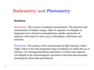
  • 1. Radiometry and Photometry Definition Radiometry: The science of radiation measurement. The detection and measurement of radiant energy, either as separate wavelengths or integrated over a broad wavelength band, and the interaction of radiation with matter in such ways as absorption, reflectance and emission. Photometry: The science of the measurement of light intensity, where "light'' refers to the total integrated range of radiation to which the eye is sensitive. It is distinguished from radiometry in which each separate wavelength in the electromagnetic spectrum is detected and measured, including the ultraviolet and infrared.
  • 2. Radiometry and Photometry F, Flux M, Flux/Proj. Area I, Flux/W L,Flux/AWE, Flux/Area Rcd. Radiant Flux Watts Luminous Flux Lumens Radiant Exitance Watts/m2 Luminous Flux Lumens/m2=Lux A / Radiance Watts/m2/sr Luminance Lumens/m2/sr 1 Lambert= (1L/cm2/sr)/p 1 ft Lambert = (1L/ft2/sr)/p 1m Lambert = (1L/m2/sr)/p Radiant Intensity Watts/sr Luminous Intensity Lumens/sr 1 Candela=1cd=1L/sr W/ Irradiance Watts/m2 Illuminance Lumens/m2= Lux 1 Ft Candle=1L/ft2 1 W is 685 L at 555 nm. Radiometric quantities are related to photometric quantities through the CIE luminous efficiency curve Photometric unit = K()  radiometric unit Where K() = 685 V()
  • 3. Radiometry and Photometry Radiometric quantities Radiometry is the science that allows us to answer “how much light is there?” Quantity Symbol Units Energy Q J Power (flux) P, Φ W Intensity I W / sr Irradiance E W / m2 Exitance M W / m2 Radiance is the most fundamental radiometric quantity Radiance W / (m2 sr) “spectral” anything = per unit wavelength or frequency ex. “spectral radiance” W / (m2 sr nm) L Q t   P W P A   2 P A   W incident exiting
  • 4. CIE Luminous Efficiency Curve Radiometric quantities are related to photometric quantities through the luminous efficiency curve. The luminous flux corresponding to 1W of radiant power at any wavelength is given by the product of 685lm and luminous efficiency at the same wavelength.
  • 5. The Unit Solid Angle One of the key concepts to understand the relationship between the different photometric quantities is that of the solid angle, or steradian. A steradian is defined as the solid angle which, from the centre of a sphere, cuts off an area of the surface of that sphere equal to the square of its radius. A full sphere therefore contains 4p steradians. The solid angle (W) in steradians is equal to the spherical surface area (A) over which it is measured divided by the square of the radius (r) at which it is measured. W = A/r²
  • 6. Radiant flux is a measure of how much radiometric power is being emitted by a source. Flux, expressed in watts, is a measure of the rate of energy flow in joules per second (J/s). Luminous flux, on the other hand, is a measure of the power of visible light. This measure depends on the sensitivity of the human eye and is therefore based on the CIE Luminous Efficacy Curve for photopic conditions. Thus the radiosity of any given light can be vastly different from its luminosity depending on the spectral content of its emission, meaning that we have to distinguish between the flow of energy (radiometric) and the flow of light (photometric). Radiant and Luminous Flux
  • 7. Irradiance is a measure of radiometric flux per unit area, or flux density, and is typically expressed in Watts per square meter (W/m²). It is basically the amount of radiometric energy flowing in a particular direction. Illuminance, however, is a measure of photometric flux per unit area, or visible flux density. Illuminance is typically expressed in lumens per square meter (lux) or lumens per square foot (foot-candles). Irradiance and Illuminance
  • 8. Radiance is a measure of the flux density per unit solid viewing angle, expressed in W/m²/Sr. Luminance is a measure of the photometric brightness of a surface and is given in cd/m² or asb. As such it is based on the amount of light being output or reflected off surfaces in the environment. The human eye and the camera both respond only to luminance. Radiance and Luminance
  • 9. Radiant Intensity is a measure of radiometric power per unit solid angle, expressed in watts per steradian. Similarly, luminous intensity is a measure of visible power per solid angle, expressed in candela (lumens per steradian). Inverse Square Law Radiant Intensity (I) is related to irradiance (E) by the inverse square law, as shown below: I = E * r² The flux leaving a point source within any solid angle is distributed over increasingly larger areas, producing an irradiance that decreases with the square of the distance Radiant Intensity and luminous Intensity
  • 10. Lambert's cosine law Flux per unit solid angle leaving a surface in any direction is proportional to the cosine of the angle between that direction and the normal to the surface. A material that obeys Lambert's cosine law is said to be an isotropic diffuser; it has the same sterance (luminance, radiance) in all directions. I() = I(0)cos (Lambert’s cosine law) If the radiance at each angle is constant then Le = I()/Acos()=I(0)cos()/Acos()= I(0) / A Thus, when a radiating surface has a radiance that is independent of the viewing angle, the surface is said to be perfectly diffuse or a Lambertian surface.
  • 11. Blackbody Radiation  “Glowing red hot”--blackbody radiation is the name given to electromagnetic radiation emitted by a heated object.  Solids and dense gases give off blackbody radiation  Thermal radiation spectrum range: 0.1 to 100 mm  It includes some ultraviolet (UV) radiation and all visible (0.4-0.76 mm) and infrared radiation (IR).
  • 12. Blackbody Radiation  A blackbody is an ideal absorber: all radiation falling on a blackbody, irrespective of wavelength or angle of incident, is completely absorbed.  A blackbody is also a perfect emitter: no body at the same temperature can emit more radiation at any wavelength or into any direction than a blackbody.
  • 13. Blackbody Radiation  Planck’s Law  1900, Max Planck derived mathematical law describing distribution of brightness in blackbody spectrum  Stefan-Boltzmann Law  Energy emission is greater at every wavelength as temperature increases; total amount of radiant energy emitted increases with increasing temperature  Wien’s Displacement Law  Maximum emission found toward shorter wavelengths (blue end of spectrum) as temperature increases
  • 14. Radiation Laws  Planck’s Law The formula describing the spectral radiant emittance of a perfect blackbody as a function of its temperature and the wavelength of the emitted radiation.  Stefan-Boltzmann Law The formula that indicates the total radiation at all wavelengths from a perfect blackbody. W Total = 5.67 x 10⁻¹² T 4(W/cm2)  Wien’s Displacement Law The formula that gives the wavelength of maximum spectral radiant emittance of a perfect blackbody: lmax = 2898/T(µm)          1 110745.3 /143885 8 T e M   (W/m2-m)
  • 15. Blackbody Radiation  Radiation emitted by stars tends to be much like that emitted by blackbody  Planck’s Law  Stephan-Boltzmann Law  Wien’s Displacement Law
  • 16. Colour  White light, or nearly white light from the Sun, contains a continuous distribution of wavelengths.  The light from the Sun is essentially that of a blackbody radiator at 5780 K.  The wavelengths (spectral colours) of white light can be separated by a dispersive medium like a prism.  Even more effective separation can be achieved with a diffraction grating. http://www.educypedia.be/education/physicsjavacolor.htm
  • 17. Colour Approximate model for sunlight:  Assume the intensities for red (R), blue (B) and green (G) are roughly equal.  Also: Ignore its emissions in the colors orange, yellow, and violet.  We call the colours R, G, and B the primary additives.
  • 18. Colour  R, G, and B Why are they the primary additives? Because experiment shows: Any perceived colour can be matched by an additive combination of R, G and B. Just choose appropriate relative intensities. Reason: The eye has three types of sensors in the retina. They are each sensitive to either R, G, or B light. Note: One way we perceive white is when all primary colors enter the eye in equal amounts.
  • 19. Rules of colour mixing: additive Additive Combining You need to know these four facts: R + G = Y (yellow). R + B = M (magenta). G + B = C (cyan). R + G + B = W (white). Important note: We are combining light sources. That is, each colour in the sum is entering our eye, simultaneously.
  • 20. Rules of colour mixing: additive
  • 21. Example: Colour TV  Most TV tubes produce color as follows:  Use three different phosphors on the screen, arranged in tiny dots.  The three phosphors produce red, green or blue light, when struck by the electron beam of the tube.  The eye integrates the tiny dots to produce a mixture of the three primaries.  The three types produce red, green or blue light when an electron beam impinges. http://www.educypedia.be/education/physicsjavacolor.htm
  • 22. Rules of colour mixing: subtractive Subtractive combining Subtractive colour mixing is the kind of mixing you get if you illuminate colored filters with white light from behind The commonly used subtractive primary colours are cyan, magenta and yellow, and if you overlap all three in effectively equal mixture, all the light is subtracted giving black. Subtractive colour mixing is more complex than the additive colour mixing you get with coloured spotlights.
  • 23. Rules of colour mixing http://www.educypedia.be/education/physicsjavacolor.htm
  • 24. Subtractive Colour Mixing: Filters Filters  A filter absorbs light of certain colours. It lets through the other colours.  Example  An ideal red filter absorbs all colours but red light. It transmits red light.  In the model W = R + G + B, the red filter absorbs blue and green light, transmits red. Subtractive Mixing Problems  Two colors are mixed finely. Or, two filters overlap.  What is the resulting colour? (Always assume white light is incident.) http://www.educypedia.be/education/physicsjavacolor.htm
  • 25. Exercise 1. We make a fine mixture of R and B paints. What color is the mixture? 2. A yellow filter is put on an overhead projector above a slit. What primary colours are absent? Why? 3. White light is incident on a pair of overlapping green and red filters. What light emerges? 4. Mix cyan and yellow paint. What is the color of the mixture? http://www.educypedia.be/education/physicsjavacolor.htm