SlideShare a Scribd company logo
1 of 16
Download to read offline
Bryan Orr
A Steam Heating Primer
hvacrschool.com/steam-heating-primer/
With cold temperatures right around the corner it is a good time to to brush up on our
steam now and no better way to do that than by reading an article by Dan Holohan.
This article was written by Dan Holohan and published at HeatingHelp.com HERE and is
reposted here with permission. This is one of the most comprehensive descriptions of
steam heating you will find anywhere, written by the man who LITERALLY wrote the book on
1/16
the subject. Enjoy!
If you ask a dozen people what the proper operating pressure for a steam system is, you’ll
probably get a dozen different answers.
Most folks just follow “what they were taught”without giving much thought to the results.
You see most steam systems run at ridiculously high pressures.
As early as 1900, residential boiler manufacturers decided that no house heating steam
system should operate at a pressure higher than two psi.They could make this statement
because it’s latent heat, not steam pressure that does the actual heating work in a
residential system.
Latent heat is the energy we put into water to get it to change state from a liquid to a gas. In
the early 1800s, an Englishman named Thomas Tredgold coined the term British thermal
unit. He defined the Btu as the quantity of heat needed to raise the temperature of one
cubic foot of water one degree Fahrenheit. After he died, folks changed the cubic foot to a
pound (which is about a pint of water). They could do that because Mr. Tredgold was just
making it up. Here’s more about this.
For instance, suppose we had one pint of 32-degree water (water can exist as a solid or a
liquid at 32 degrees. Did you know that?). If we wanted to raise that pint of water to 212
degrees, we would have to add about 180 Btu of heat. That would give us one pint of water,
not steam, at 212 degrees (You see water can also exist as a liquid or gas at 212 degrees).
But how do we get that pint of water to change state and become steam? We do it by adding
a great deal of latent heat. You know the old saying, “A watched pot never boils?” Well, it’s
certainly true because to make that pint of water turn into steam we have to add 970.3 Btu!
Think of it. It only took 180 Btu to get that pint of water to rise from 32 degrees to 212
degrees. But it took more than five times the heat (970.3 Btu) to get it to move from 212
water to 212 steam. There was no change in temperature, but there sure was a change in
the energy content.
This energy is latent heat; it’s what heats the house. We get nearly all of it back when the
steam condenses in the radiators. Steam can heat when it’s at zero-psi pressure. You see
you don’t need a lot of pressure to heat the building. All you need is latent heat.
To prove this is true, consider this: If you add only ten more Btu of latent heat per pound of
steam to zero-psi steam, you’ll wind up with steam at ten psi. That ten additional Btu is
insignificant when it comes to heating the building, but it can cause us many problems with
the system. As you’ll see.
2/16
The job of steam pressure is strictly to overcome the friction that steam meets as it works its
way around the system. All we have to do is supply enough pressure back at the boiler to
overcome the system piping’s friction.
And the pressure you need is remarkably low because years ago, fitters sized pipe to offer
very little resistance to steam flow. In fact, we measure this pressure in ounces per 100 feet
of piping. This is why boiler manufacturers decided so many years ago that all you need is
two psi to operate any house heating system. Raising the pressure higher than two psi will
only cause you problems because steam is a gas. When you raise the pressure of a gas, you
compress it. Just think about what happens when you put air in your car’s tires. And if you’d
like to learn more about this, click HERE.
Steam is a gas, just like air. When you compress it, it just naturally takes up less space. The
amazing thing is that it also begins to move more slowly. It’s not as “large,” so It can afford to
move more slowly. Strange as it may seem, it takes longer for high-pressure steam to get
out to the radiators than it does for low-pressure steam. Also, high-pressure steam, since
it’s more tightly packed, will call more water out of the boiler than low-pressure steam. This
can lead to low-water problems back at the boiler.
Steam travels across a system because of a subtle difference in pressure. Besides friction,
the fire in the boiler and the condensing of the steam in the radiators also leads to a
difference in pressure throughout the system. The fire creates the initial pressure. Since all
the air vents are open, the inside of the piping system is at atmospheric pressure (which is
14.7 pound per square inch at sea level and different in other parts of the country). Steam
begins to move from the higher pressure in the boiler to the lower pressure in the system.
But as soon as it begins to move, it also begins to condense into water. This is because the
pipes are cold and the steam is hot. When steam condenses into water it leaves a partial
vacuum in its place. The condensing process causes this vacuum.
This is a fine point you’ve probably never thought about. Steam occupies about 1,700 times
the volume of water. That means that if you filled an eight-ounce glass with water and
boiled it, you would have to have1,700 eight-ounce glasses available to catch the steam! A
pint of water, once boiled, balloons out to fill a cubic yard! It’s like popcorn.
This also means that when steam condenses in the radiators it will shrink to 1/1700th of the
space it occupied as steam. What we’re left with (as long as the air vents remain closed) is a
partial vacuum.
This is good because it makes the steam travel to where you need it up in the radiators. This
is why you don’t need pumps to move steam. All you need is a subtle difference in pressure.
Now think about this. As the radiator heats, the condensing rate in that particular radiator
will slow, right? In fact, it will eventually reach a point when very little steam is condensing.
3/16
The metal will have reached steam temperature; the room will have reached the setting of
the thermostat. It’s nature’s job to equalize temperature as well as pressure.
And this is also a fine thing because it allows the steam to travel on to the next radiator
down the line. The boiler’s job is simply to get steam (a gas) out to the last radiator before it
turns into water (a liquid). If the boiler is too small for that task, the building will be partially
hot and partially cold you’ll wind up with problems.
You see when you’re working with steam heat, you’re really watching a race between the
steam and the cold pipes. If the boiler is properly sized,the steam will win that race. This is
why we size replacement steam boilers by measuring the radiators. As strange as it may
seem, the heat loss of the building is not important. Only the “race” matters. We have to “fill
that steel balloon” (the piping system) with steam before it can condense into water. As far
as the replacement boiler is concerned, it doesn’t matter if the homeowner insulated every
nook and cranny and replaced all the windows in the house. If the piping and radiators are
there, you have to fill them with steam. It’s as simple as that.
Don’t make the mistake of sizing the new boiler by taking the information off the old boiler.
The person who did that sizing may have been wrong. Or, someone may have removed or
added radiators over the years. Don’t take a chance; do it right.
And keep in mind, too, that there’s a safety factor you have to add to the net radiation load
to allow for the heating of the pipes. We call this the “pick-up” factor. Nowadays, we allow an
additional 33%. Years ago, that safety factor was much larger, so when sizing a replacement
steam boiler, the age of the system also matters.
This “pick-up” factor is the difference between the Net Ratings (the actual radiation load)
and the DOE Heating Capacity Rating (the radiators and the pipes). The firing rate of the
boiler should match the DOE Heating Capacity rating of the system (that’s piping plus
radiation).
Let’s take a look at some of the other changes manufacturers have made to boilers in recent
years.
The importance of the Piping Around the Boiler
As boilers became smaller, the piping around them became more and more important.
Today’s replacement steam boiler contains much less water than the boilers of yesteryear.
And yet the new boiler produces just as much steam as the old boiler! Modern oil burners
and improved boiler design make this possible. But if you want that job to be successful you
have to pay careful attention to the boiler manufacturer’s near-boiler piping specifications.
Ignore them at your own risk!
4/16
The purpose of the piping specification is to give you a boiler that delivers dry steam. Dry
steam contains a great deal of latent heat. If you add even a little moisture to the steam by
piping the boiler incorrectly (and letting the water leave the boiler with the steam), the latent
heat content of the steam will suffer. The steam, in essence, will condense in the moisture
before it has a chance to reach the radiators. In short, the steam will lose the “race” to that
last radiator and parts of the building will be cold.
And not only will the building heat unevenly, the fuel consumption will also increase
because the pressuretrol will never reach its high limit. And to make things worse, you’ll
probably also have water hammer. That’s the knocking in the pipes that people who don’t
know any better think of as normal. Follow the boiler manufacturer’s instructions to the
letter and you’ll avoid most of the common problems associated with steam. Here are a few
of the things the boiler manufacturers will tell you to do:
Allow at least 24 inches between the top of the boiler and the bottom of the steam
header.
Use full-size risers to the header.
Pipe the system take-offs at a point between the last riser to the header and the
equalizer.
Pipe the swing joints into the header. Use a reducing elbow to connect the header to
the equalizer.
You’ll probably also see a section on how to clean the boiler after you’ve worked on it.
There’s really no way around this; all steam boilers must be cleaned after they’re installed.
You don’t necessarily have to do it immediately, but you do have to do it. It often pays to let
the system run for a few days before you go back to give it a good cleaning. Waiting a few
days gives the oil and dirt a chance to settle on the surface of the water.
There are many opinions on the best way to clean a steam boiler. One of the oldest ways is
to dissolve a pound of tri-sodium phosphate (TSP) and a pound of caustic soda (lye) in water
and pour it into the boiler. Let it cook for a few hours and then drain the boiler. If you can’t
buy TSP in your town, try a commercial soap called MEX. It works well and will not damage
the rubber gaskets found in some boilers. However, before you clean any boiler, check the
manufacturer’s instructions for their recommendations.
Skimming the boiler is the best way to remove surface oil. You’ll know there’s oil in the
boiler if you see any moisture at all in the gauge glass above the water line. Many
technicians are tricked into believing the water is clean just because it appears to be clear in
the gauge glass. But they’re in for a surprise because oil can be colorless in boiler water. The
part of the gauge glass above the water line should be bone dry. It should look like someone
just ran a dishtowel through it.
5/16
If you have a surging water line and there’s moisture in the gauge glass try cold skimming
the boiler. You do this by opening a horizontal tapping above the water line and installing a
six-inch nipple. Open the feed-water line slowly until the water level rises to the center of
the nipple and spills out. Don’t be in a hurry. If you rush, you’ll be skimming from below the
surface of the water and accomplishing nothing.
Let the water run slowly from the skim port for several hours. Check it periodically by taking
a sample of the water and boiling it on the customer’s stove in a small pot. If there’s oil in
the water, the water will foam when it boils.
Keep skimming and checking until your sample boils like tap water; that’s when you know
you’re done. Remove the nipple and start the boiler. In most cases, your surging problems
will become just a bad memory.
Skimming from the top of the boiler doesn’t work as well because the rising water will cling
to the metal before it has a chance to get out of the boiler. Draining from the bottom of the
boiler doesn’t work as well as horizontal skimming either for the same reason.
Firing a small boiler while skimming is ineffective because the surface oil will be emulsified
in the water. Just think about what happens to the oil you add to a pot of boiling water
before you drop in that pound of spaghetti. Oil doesn’t stay on the surface when the water
is boiling. This is especially true in a highly efficient, low-water-content boiler.
Cold, horizontal skimming works pretty well most of the time, if the boiler’s been up and
running for a while.
Let’s take a look at several different types of steam systems.
One-pipe Steam
One-pipe steam takes its name from the single pipe that connects each radiator to the
steam main. Both steam and condensate travel in this pipe, but in opposite directions. This
is what often makes one-pipe steam so difficult to manage. When steam and condensate
travel in opposite directions (what we call “counterflow”) you have to pay close attention to
the size and pitch of the pipes. For instance, when steam and condensate move in the same
direction (that’s “parallel flow”) the pitch should be at least one inch in twenty feet. When
there is counterflow, however, the pitch must be at least one inch in ten feet. See? It
doubles.
The exception to this is when you have a horizontal
run-out to a radiator riser. Here, the pitch should be at
least one-inch inch per foot. Where you can’t get this
pitch, (or when the horizontal run-out is longer than eight feet) you have to go to the next-
size pipe.
6/16
The rules are fairly simple, but few people take the time to learn them. That’s why you wind
up with so many radiators that bang and so many air vents that spit. If you’re adding or
removing radiators, get some advice from a reputable supplier of steam specialties. They’ll
be able to help you out with the pipe sizing and pitch.
Let’s take a look at the basic controls on a one-pipe (and a two-pipe) system.
The pressuretrol determines the operating range of the boiler during the heating cycle. It’s
important to understand that a heating boiler doesn’t make steam all the time. It only does
that when the thermostat clicks on. During a call for heat, the boiler will cycle up to the cut-
out setting of the pressuretrol. At that point, the pressuretrol will shut off the burner.
Some pressuretrols show the cut-out setting as “Differential.” Usually, you’ll add that
“Differential” to the “Cut-In” setting to get the”Cut-Out” setting. Be careful, though, because
some pressuretrols show”Differential” as a number to be subtracted from the cut-out
setting.Take a few minutes to read the instructions and think about what the manufacturer
is telling you.
When the pressuretrol reaches its cut-out setting,
steam will be moving out into the system and condensing in the pipes. This condensing
process will cause an overall drop in system pressure. When the system cycles down to the
cut-in pressuretrol setting, the pressuretrol will re-start the burner, as long as the
thermostat is still calling for heat. If the thermostat isn’t calling for heat, the burner will
remain off, and the steam pressure will drop to zero (atmospheric pressure).
Usually, you should set the pressuretrol to turn the burner on at one-half psi and off at the
lowest possible pressure required to heat the furthest radiator. If that pressure winds up
being more than 2 psi, something is probably wrong. Most likely, the air vents aren’t working
properly.
Years ago, fitters used vaporstats to control the boiler. These are like pressuretrols, but
they’re much more sensitive. A vaporstat measures pressure in ounces. They’re still
available today, but they’re more expensive than pressuretrols. Nevertheless, along with
quality air vents, a vaporstat is probably the best investment you can make. You see when it
comes to steam, low pressure is the key to success.
If you’re concerned about the burner because it’s short-cycling, look to the air vents, not the
pressuretrol. Main vents are the key here. Get rid of the air and the building should heat
without short cycling.
Commercial boilers also require a manual-reset, high-limit pressuretrol to shutoff the
burner should the pressure rise too high. Make sure you instal this with the operating
7/16
pressuretrol, but not on the same pigtail.
Speaking of which, you pipe the pressuretrol to a steam pigtail
so you’ll have a water seal between the control and the boiler. The water protects the
control from the steam temperature and extends its life. Obviously, you should not have a
valve between the boiler and the pressuretrol. If the pigtail clogs (which it will!) replace it
with a new one. If you’re burner is short cycling, it may be because the pigtail is clogged.
Check it out.
The relief valve protects the boiler against a runaway fire. On space-heating steam boilers
the relief valve is set to pop at 15 psi. This is the limit for any low-pressure boiler.
The relief valve should be rated by the American Society of Mechanical Engineers (ASME, for
short), and you should size it for the maximum load of the boiler. For safety, pipe it to a
drain, or to within a few inches of the floor.
It’s not a good idea to pipe the relief valve to the outdoors because, should it pop off, water
will be held in the pipe by vacuum, much as water is held in a straw when you put your
finger over one end. During the winter, the trapped water in a relief line that’s piped to the
outdoors can freeze and block the escaping steam as surely as a pipe plug will. That’s
dangerous! If you must pipe the relief valve to the outside, use a vacuum breaker at the
discharge of the valve. This will allow the water to drain the water from the line after the
relief valve has popped. It’s best to avoid this altogether if you can, though. And naturally,
there should never be any valves between the relief valve and the boiler or the relief valve
and the drain line.
The low-water cutoff is required by code. Its job is to shut off the burner should the water
level fall to an unsafe point. The boiler manufacturer determines this level, but it’s usually
within one-half inch of the bottom of the gauge glass.
The low-water cutoff can be a float-type or a probe-type.
Probe-type low-water cutoffs are becoming very common on low-water-content boilers
because these cutoffs have timing devices to prevent nuisance shut-downs should the boiler
water surge. Probe-type cutoffs send a low-voltage charge through the water to ground on
the boiler’s metal. Don’t use a probe control without first getting the boiler manufacturer’s
recommendations as to where they want it installed.
Float-type cutoffs mount directly on the gauge glass of the boiler and sense the movement
of the water line mechanically. The low-water cutoff manufacturer determines where the
cutoff belongs. You should never tamper with these settings.
Some installers try to make the boiler more “automatic” by raising the low water cutoff so
that it covers the domestic water coil all year long.This, they think, will save the homeowner
the trouble of raising the level by hand during the summer. But it’s a bad idea because it
8/16
also creates a “normal” water line that’s several inches too high. It brings the boiler water
too close to the steam outlet and drives water up into the system. Before you know it, you
have more problems than you bargained for. Save yourself a headache and have the
customer cover the tankless coil by hand once a year.
The gauge glass is your way of knowing where the water is in the boiler. Expect to see some
minor movement in the water line. Anything between a half- and three-quarters of an inch
of up-and-down movement is normal.
When the boiler is off, the “normal” water line is the center of the gauge glass. When the
system is running, the “normal” water line is near the bottom of the gauge glass. That’s
because the water, in the form of steam and condensate, is out in the system. When the
burner shuts down, the level will return to the center of the gauge glass again. Don’t try to
keep the water in the center of the glass when the system is running because, obviously,
this will cause the boiler to flood when the condensate finally returns on the down cycle.
Again, this is why you shouldn’t tamper with the low-water cutoff level.
The automatic water feeder (if you’re using one) is there to maintain a safe minimum water
line. It is not there to maintain a “normal” water line when the boiler is off.
A water feeder will protect the system against freeze-ups if the people are away in the
winter and, say, an underground return should spring a leak. Without the feeder, the low-
water cutoff would shut down the burner and the house would freeze up.
So, while it’s not essential to the system’s operation, you can consider an automatic water
feeder a useful back-up safety device. In addition, a feeder will provide some convenience in
an old system that’s prone to leaks. The feeder will maintain an operating water level rather
than have the burner shutting down daily on low water.
If the customer doesn’t want his leaking, buried returns replaced, an automatic feeder
makes a lot of sense. But naturally, a great deal of fresh feed water can also harm the boiler
through oxygen corrosion. Think about this when you’re advising the customer. Give them
the facts and their options. Then, leave the decision to them.
Let’s take a minute now to define some terms.
A wet return is any pipe that’s below the boiler water line. A dry return is any pipe that’s
above the water line.
The header is the large horizontal pipe directly above the boiler. You have to size it to carry
the entire steam load of the boiler. Nowadays, the boiler manufacturer will often oversize
the header so it acts as a point of low velocity. That gives the steam a place where it can
9/16
slow down and dry out before it heads out into the system piping. Always check the boiler
manufacturer’s requirement on header size before you install a replacement steam boiler.
You’ll often find that the old header is too small for the new boiler.
Risers are the pipes between the boiler and the header. They must be the full size of the
boiler tapping. Don’t reduce them because you’ll cause the steam to move too fast. When
that happens, the steam will pull some of the water out of the boiler and throw it into the
system piping.
Many of the newer boilers call for two (or three!) risers to the header. The older boiler may
not have needed as many. If you go with the old piping and ignore the manufacturer’s
instructions for the new boiler, the new boiler’s water line might wind up tilting at a severe
angle. That can lead to very wet steam and, in many cases, a broken boiler because the
flame will be licking at the boiler’s exposed crown. Without water to carry off the heat, a
boiler can crack.
If the boiler has more than one outlet, it’s also important to remember to pipe the headers
with swing joints. If you don’t, the boiler sections can be split wide open like an accordion
when the horizontal header heats and expands.
If you have such a boiler with more than
one outlet (and swing joints) you
shouldn’t use copper instead of steel for your header. This is because copper expands twice
as much as steel. That can cause the soldered joints to come apart and leave your customer
with steam leaks. Consider, too, that when you use copper in a steam system there will be
more corrosion than normal because of the dissimilar metals. Copper, steel, and iron lead
to corrosion at the places where they come together.
Take-offs are the pipes connecting the header to the system. You probably won’t be
changing these. The original installer sized them to handle the connected load. Sometimes,
someone adds radiation to the existing take-off, and you should watch for this because it
can cause you service problems. The take-off might not be able to carry the additional heat
on a cold day. Any reputable manufacturer of steam-heating equipment will be able to
check the size of the take-off against the connected load and advise you.
The boiler manufacturer determines the size of the equalizer. Its job is to return any water
that slips out of the boiler with the steam, and also to balance the pressure between the
supply and the return sides of the boiler. Without a properly sized equalizer, water can back
out of the boiler.
Never pipe a steam take-off over the equalizer. The steam’s velocity can create a pressure
drop in the equalizer that will lift the water up, causing a corresponding drop in the boiler’s
water line.
10/16
In 1919, the Hartford Steam Boiler Insurance and Inspection Company invented the
Hartford Loop. Its job was to prevent water from leaving the boiler, should a return line
spring a leak. Here’s more about the Hartford Loop.
The connection between the loop and the equalizer must be made with a close nipple to
prevent water hammer. This is because steam is forming in the Loop connection. Returning
condensate can cause this steam to rapidly condense and shrink to 1/1700th its steam
volume. The water rushes into fill the void. As the condensate slams against the back of the
tee, you wind up with water hammer in the return.
The dimension labeled “A” in the diagram represents the distance you have to maintain
between the center of the gauge glass and the bottom of the lowest dry return in the
system. In one-pipe systems that have DOE Heating Capacities greater than 100,000 BTUs,
“Dimension A” must not be less than 28 inches.
“Dimension A” provides the force that puts the
condensate back in the boiler.Without it, water will back up into the horizontal piping and
shut off the take-offs to the radiators. The house will heat very slowly (if at all), and certainly
very unevenly. You’ll probably also have water hammer.
And this is also why you don’t see main vents on many of jobs. They’re installed improperly
and get damaged on the first few cycles. That’s a shame because main vents are the key to
good one-pipe steam operation. If you’re using good main vents near the ends of every
main, steam will travel very quickly to every radiator in the building. Vent large radiators
quickly and small radiators slowly no matter where they are in the building. Focus on the air
content of the radiator rather than its location in the building.If your main vents are
working, steam will arrive at each radiator at about the same time.
Baseboard over three feet long has no place in a one-pipe steam system. In most cases, you
can never get the pitch or size you need to keep the air vent from spitting water up at the
ceiling. If you must use baseboard, connect it with two pipes, vent the outlet side, and drip
the return pipe immediately into a wet return. Do not use a steam trap; just drip it into a wet
return. Pitch the baseboard run toward the return as much as you can.
Let’s take a look at another type of system now.
Two-pipe Steam
Like one-pipe, two-pipe steam takes its name from the number of connections you’ll find at
the radiator. As heating jobs got larger in the old days, fitters found it made good sense to
have just steam in one pipe and just condensate in the other. That way, each pipe could be
smaller and the pitch of the pipes became less crucial because everything was moving in the
11/16
same direction.
Ina two-pipe steam system, the steam connection is
usually at the top of the radiator; the condensate connection is at the bottom on the
opposite side, but this doesn’t always have to be the way. You can also have the inlet and
outlet at the bottom of the radiator at opposite ends. Or you can have the inlet at the top,
and the outlet at the bottom, on the same side of the radiator.
At the turn of the century there was a type of steam system called the two-pipe, air-vent
system. This system had two pipes (and two supply valves) at opposite ends of the bottom
of the radiator. Since this system didn’t use steam traps (they hadn’t invented them yet!),
both pipes carried steam. It worked because of the air vents. One pipe was always larger
than the other. The larger pipe was always on the inlet side of the radiator. When the steam
traveled through the system, it favored the larger pipe because that’s where the least
resistance to flow was.
But this was an expensive system to install because there were twice as many pipes as a
one-pipe system, and it offered an advantage only when the radiators were very large. With
a large radiator, you have a lot of condensate flowing backward down the one-pipe supply
line. That can create water hammer.
The two-pipe steam system died an early death and has been obsolete for many years. But
there are still many of them around. They were popular in municipal-type buildings such as
schools and courthouses. If you see two supply valves at the bottom of the radiator, you
probably have one of these old systems. Be careful. This system is easily confused with true
two-pipe steam. However, it works differently and can cause quite a few problems should
you make certain piping changes to the system.
True two-pipe steam uses thermostatic steam traps on the radiators. The steam trap has
three jobs It opens to let air pass through the radiator and into the return piping. Air is a
great insulator. If left in the radiator, you’ll have a cold room. Also, when water boils, it
releases a great deal of carbon dioxide because of carbonates and bicarbonates that are
common to freshwater. This carbon dioxide will travel through the system and mix with
condensate to form a mildly corrosive carbonic acid. Naturally, this acid is harmful to the
radiators and also to the returns. This is another reason why good main air vents are so
important to steam systems. You have to get rid of that carbon dioxide before it mixes with
the condensate. So steam traps are actually air vents as well!
The second job of the steam trap is to close when steam reaches it. Radiator steam traps
have thermostatic bellows. Manufacturers fill these bellows with a mixture of alcohol and
water. They use alcohol because it boils at 170 degrees at atmospheric pressure (water
boils at212). The alcohol/water mixture is usually set to boil at about 180degrees. When
steam reaches the radiator trap, the alcohol “flashes”and expands the bellows. There’s a
12/16
pointed metal rod, called a “pin,”on the bottom of the bellows. When the bellows expands, it
pushes this pin down into the trap’s seat. The trap is now closed and no steam can escape.
With nowhere to go, the steam condenses and gives up its latent heat to the room. Should
the bellows fail a good deal of the steam will pass into the returns and heat the insides of
the building’s walls instead of the rooms where the people are. This is wasteful, noisy (water
hammer) and destructive to the condensate pump, if you’re using one. But a failed trap is
hard to spot because the radiator will continue to heat. It won’t look any different from the
outside,
The third job of the trap is to open once the condensate has cooled. The condensate will
pass through the trap and flow downhill to the boiler.
Most radiator trap elements have a life span of about three years. This is because the
element flexes about 155,000 times per heating season. This near-constant movement,
combined with water hammer, is what kills the elements. Unfortunately, most people check
traps about once every 30 years!
You can check radiator traps with a temperature-sensitive crayon called a TempilStick or
with a temperature probe. There should be about a 20-degree difference across an
operating trap. The problem is that if just one trap fails, the steam passing into the returns
can trick you into thinking a nearby trap has also failed.
It helps to check the system backward, starting with a large return and working up toward
the branches. This should reveal problem areas. Then it’s just a matter of isolating radiators
and checking them. True, it’s time-consuming, but it’s also necessary.
Steam traps also have a curious effect on the system’s returns. Because they close to steam,
traps prevent steam from getting into the returns. Remember what we said about the one-
pipe system? Water returned to the boiler because of the static weight of the water in
“Dimension A” and the “leftover” steam pressure at the end of the main.
With two-pipe, you no longer have “leftover” steam pressure to put the condensate back in
the boiler. This is because of the traps. This means that the only force you can depend on is
the static height in “Dimension A.”
With two-pipe steam, “Dimension A” must be at least 30 inches for every pound of pressure
in the boiler. In other words, if you fire the boiler at 2psi, you’ll need 60 inches of height
between the center of the gauge glass and the bottom of the lowest steam main. If you fire
5 psi, you’ll need 12-1/2 feet between those two points!
It’s another good reason to keep that steam pressures low, isn’t it?
13/16
This is why you’ll often see condensate pumps being used on two-pipe steam systems. The
pump provides the pressure needed to put the condensate back in the boiler because the
basement isn’t deep enough to the returning condensate enough static weight.
A condensate pump is the low point in the system. Everything
must flow downhill to it. If any part of the system piping dips
below the condensate pump inlet, you’ll have water hammer shortly after the system first
starts up.
A condensate pump has a receiver made of either steel or cast-iron(cast-iron lasts much
longer than steel because condensate is corrosive). This receiver is nothing more than a
gathering chamber for returning condensate. It’s vented to the atmosphere because, for the
most part, condensate receivers aren’t rated to withstand any pressure. If you plug the
receiver vent, the receiver can explode!
Inside the receiver is an electrical float switch. This switch turns the pump on when the
water level inside the receiver rises, and off when it falls.
On the discharge side of the pump you’ll find a check valve (to keep the boiler water in the
boiler) and a throttling valve. The throttling valve is there to slow the pump down. You see
most condensate pumps will discharge at 20-psi pressure. That’s too high for most heating
applications (It’s not too high for commercial applications, however). The throttling valve will
stop the check valve from chattering by adding resistance to the pump’s pressure. You just
crank the valve down until the noise stops.
A condensate pump has no way of knowing if the boiler it serves needs water or not. When
it fills, it dumps; it’s as simple as that.
Because of this, boiler-feed pumps are sometimes used in place of condensate pumps. This
is especially true with modern, low-water-content boiler.
A boiler-feed pump is different because a float switch located on the boiler, not in the
pump’s receiver, controls the pump. With a boiler-feed pump, the pump can come on only if
the boiler needs water.
The receiver in the boiler-feed pump is also much larger
than the condensate pump’s receiver. This oversized receiver gives the condensate a place
to wait until the boiler needs it.
Be careful when you replace an old boiler on a two-pipe system with a new boiler. You may
find that the old condensate pump isn’t compatible with the new boiler. You may need a
boiler-feed pump.
14/16
Hanging a storage tank on the side of the boiler is no substitute for a boiler-feed pump. First
of all, all the reserve water would have to be located within the three inches, or so, of boiler
operating range. This leads to very long and very narrow tanks.
But more important, that additional water would have to be brought to steam temperature
on each firing cycle. The tank will typically contain about125% of the water in the boiler! This
kills the overall operating efficiency of the boiler and can cause the customer to use more
fuel than he would have with his old boiler.
When you’re using a condensate or boiler-feed pump, or when the two-pipe system has dry
returns, you’ll find float-and-thermostatic (F&T) traps at the ends of the steam mains. These
larger traps keep steam from reaching through to the dry return piping.
The thermostat in the F&T trap is there strictly to pass air to the vent on the condensate
pump. The condensate passes through the trap by lifting a float. This float is very similar to
the ballcock in a toilet tank.
The trap is normally closed. Steam can’t pass through the trap
when the ball is down because the lever attached to the ball is also attached to the trap’s
pin, and that pin is firmly seated in the trap’s outlet. Since steam can’t escape, it will
condense. It’s this condensing steam that eventually raises the float ball and opens the trap.
When the trap opens, the higher pressure on the trap’s inlet pushes the condensate
through the trap and into the return line. When the trap goes dry, the ball drops the pin
back into the seat and keeps the steam from escaping.
Because the trap is normally closed, it, too, will have an effect on the returning condensate.
You’ll need 30 inches of height between the trap and the center of the gauge glass for every
pound of pressure in the boiler. That is, of course, unless you have a condensate or boiler-
feed pump supplying the return pressure.
This is a good place to mention that motorized zone valves on the steam takeoffs have the
same effect on returning condensate as traps. You should never use them on a steam
system unless you also use a condensate or boiler-feed pump, and F&T traps.
Since F&T traps are mechanical devices, they’re not sensitive to temperature (thermostatic
radiator traps are sensitive to temperature).There is no noticeable drop in temperature
from one side to the other of an F&T trap. They discharge water at the same temperature as
steam. Remember what we said about steam in the section on “How Steam Heats?” It can be
either a liquid or a gas at the same temperature, right? The difference between the two is
latent heat, and you can’t measure latent heat with a thermometer. This is where things get
a bit tricky because you can’t check an F&T trap with a TempilStick (908-757-8300) or a
temperature probe. There’s no difference in temperature across an F&T trap, even when the
trap is operating!
15/16
The way to check F&T traps is to open a union or a valve on the discharge side and look at
what comes out. If the trap isn’t operating properly, there will be several inches of invisible
steam and then a plume of vapor. If the trap is operating, you will see only vapor and water.
This is why it’s a good idea to install new F&T traps with a drain valve and a shut-off valve on
the discharge side. These two valves make troubleshooting very easy.
Most F&T traps fail because they are oversized. You should never size an F&T trap to match
the line size. This causes the seat to withdraw and leak in no time at all.
Trap sizing isn’t difficult, but you do need to know how much condensate will be passing
through the trap and at what pressures (both supply pressure and back pressure). Seek the
advice of a reputable steam trap manufacturer if you’re not sure what to do.
In recent years, many older, two-pipe steam systems have been retrofitted with non-electric
thermostatic radiator valves. These valves sense the air temperature in the room and open
or close the steam supply to the radiator. They’re installed in place of the supply valve.
Because no condensate travels down the supply pipe in a two-pipe system, you can throttle
the supply valve without getting water hammer.
These thermostatic radiator valves make the system more efficient because they prevent
the radiator from overheating. They also compensate for outside heat sources such as
sunlight, machinery and people.
Take your time and always keep in mind that all steam
systems operate on the simple law of pressure differential. High pressure will always move
toward low pressure. And those pressures are usually very subtle.
It’s as simple as that!
Want to learn more? Check out Dan Holohan’s book The Lost Art of Steam Heating.
See more at: https://heatinghelp.com/systems-help-center/a-steam-heating-
primer/#sthash.UsaILjyf.dpuf
P.S. – Big thanks to Erin Holohan for allowing me to repost this. I had the privilege of
meeting Erin at the AHR Expo last month and she was very kind and generous with her time
in speaking with me.
16/16

More Related Content

What's hot

AmbiRad general presentation
AmbiRad general presentationAmbiRad general presentation
AmbiRad general presentationLee Herbert
 
Zmr heat pump
Zmr heat pumpZmr heat pump
Zmr heat pumpZMERLY & CO
 
Final report project (THESIS ) LAST YEAR {MECHANICAL 4TH YEAR}
Final report  project (THESIS ) LAST YEAR  {MECHANICAL 4TH YEAR}Final report  project (THESIS ) LAST YEAR  {MECHANICAL 4TH YEAR}
Final report project (THESIS ) LAST YEAR {MECHANICAL 4TH YEAR}ANSHUMAN BAJPAI
 
Patio heater
Patio heaterPatio heater
Patio heaterPatio Heater
 
Water heater buying guide
Water heater buying guideWater heater buying guide
Water heater buying guideRahulSingh3575
 
Efficient use of steam in heat exchanger
Efficient use of steam in heat exchangerEfficient use of steam in heat exchanger
Efficient use of steam in heat exchangeriqbal_abbas93
 
Project A Thermoacoustics
Project A ThermoacousticsProject A Thermoacoustics
Project A ThermoacousticsAravind Badiger
 
Experimental and computational investigation of low cost standing wave thermo...
Experimental and computational investigation of low cost standing wave thermo...Experimental and computational investigation of low cost standing wave thermo...
Experimental and computational investigation of low cost standing wave thermo...IAEME Publication
 
2013-fall-aggie_challenge-madsen-team-poster
2013-fall-aggie_challenge-madsen-team-poster2013-fall-aggie_challenge-madsen-team-poster
2013-fall-aggie_challenge-madsen-team-posterLeping(David) Yu
 
Zmr heating system innovation
Zmr heating system innovationZmr heating system innovation
Zmr heating system innovationZMERLY & CO
 
Experimental investigation of waste heat recovery system for domestic refrige...
Experimental investigation of waste heat recovery system for domestic refrige...Experimental investigation of waste heat recovery system for domestic refrige...
Experimental investigation of waste heat recovery system for domestic refrige...IAEME Publication
 
PHY300 Chapter 14 physics 5e
PHY300 Chapter 14 physics 5ePHY300 Chapter 14 physics 5e
PHY300 Chapter 14 physics 5eBealCollegeOnline
 
2010 Building Science Corporation Expert Session - Mechanical System Selection
2010 Building Science Corporation Expert Session - Mechanical System Selection2010 Building Science Corporation Expert Session - Mechanical System Selection
2010 Building Science Corporation Expert Session - Mechanical System SelectionPetersen Engineering, Inc.
 
102108587 furnace-construction-operations
102108587 furnace-construction-operations102108587 furnace-construction-operations
102108587 furnace-construction-operationsGULFAM KHALID
 
Thermo acoustic refrigiration
Thermo acoustic refrigirationThermo acoustic refrigiration
Thermo acoustic refrigirationcit-cit
 
Central steam heating system report
Central steam heating system report Central steam heating system report
Central steam heating system report Zavain Rehman
 

What's hot (20)

AmbiRad general presentation
AmbiRad general presentationAmbiRad general presentation
AmbiRad general presentation
 
Zmr heat pump
Zmr heat pumpZmr heat pump
Zmr heat pump
 
Final report project (THESIS ) LAST YEAR {MECHANICAL 4TH YEAR}
Final report  project (THESIS ) LAST YEAR  {MECHANICAL 4TH YEAR}Final report  project (THESIS ) LAST YEAR  {MECHANICAL 4TH YEAR}
Final report project (THESIS ) LAST YEAR {MECHANICAL 4TH YEAR}
 
Patio heater
Patio heaterPatio heater
Patio heater
 
Water heater buying guide
Water heater buying guideWater heater buying guide
Water heater buying guide
 
Efficient use of steam in heat exchanger
Efficient use of steam in heat exchangerEfficient use of steam in heat exchanger
Efficient use of steam in heat exchanger
 
Project A Thermoacoustics
Project A ThermoacousticsProject A Thermoacoustics
Project A Thermoacoustics
 
206407531 31
206407531 31206407531 31
206407531 31
 
Experimental and computational investigation of low cost standing wave thermo...
Experimental and computational investigation of low cost standing wave thermo...Experimental and computational investigation of low cost standing wave thermo...
Experimental and computational investigation of low cost standing wave thermo...
 
TAR ppt
TAR pptTAR ppt
TAR ppt
 
Boiler
BoilerBoiler
Boiler
 
SP1037 TECHFEST
SP1037 TECHFESTSP1037 TECHFEST
SP1037 TECHFEST
 
2013-fall-aggie_challenge-madsen-team-poster
2013-fall-aggie_challenge-madsen-team-poster2013-fall-aggie_challenge-madsen-team-poster
2013-fall-aggie_challenge-madsen-team-poster
 
Zmr heating system innovation
Zmr heating system innovationZmr heating system innovation
Zmr heating system innovation
 
Experimental investigation of waste heat recovery system for domestic refrige...
Experimental investigation of waste heat recovery system for domestic refrige...Experimental investigation of waste heat recovery system for domestic refrige...
Experimental investigation of waste heat recovery system for domestic refrige...
 
PHY300 Chapter 14 physics 5e
PHY300 Chapter 14 physics 5ePHY300 Chapter 14 physics 5e
PHY300 Chapter 14 physics 5e
 
2010 Building Science Corporation Expert Session - Mechanical System Selection
2010 Building Science Corporation Expert Session - Mechanical System Selection2010 Building Science Corporation Expert Session - Mechanical System Selection
2010 Building Science Corporation Expert Session - Mechanical System Selection
 
102108587 furnace-construction-operations
102108587 furnace-construction-operations102108587 furnace-construction-operations
102108587 furnace-construction-operations
 
Thermo acoustic refrigiration
Thermo acoustic refrigirationThermo acoustic refrigiration
Thermo acoustic refrigiration
 
Central steam heating system report
Central steam heating system report Central steam heating system report
Central steam heating system report
 

Similar to A Steam Heating Primer

How to Size a Condensate Return Unit
How to Size a Condensate Return UnitHow to Size a Condensate Return Unit
How to Size a Condensate Return UnitKevin Doyle
 
Guide to Furnace Sootblowing
Guide to Furnace SootblowingGuide to Furnace Sootblowing
Guide to Furnace SootblowingRichard Smith
 
Designing an HVAC System
Designing an HVAC SystemDesigning an HVAC System
Designing an HVAC Systemoverconfidentre86
 
Heat pump vs furnace
Heat pump vs furnaceHeat pump vs furnace
Heat pump vs furnaceAhmad Affan
 
Boiler oepration Feed manufacturing.pdf
Boiler oepration Feed manufacturing.pdfBoiler oepration Feed manufacturing.pdf
Boiler oepration Feed manufacturing.pdfRaymondMhona1
 
Understanding the impact of operating with low feedwater heater levels ener...
Understanding the impact of operating with low feedwater heater levels   ener...Understanding the impact of operating with low feedwater heater levels   ener...
Understanding the impact of operating with low feedwater heater levels ener...Jagadish Patra
 
All about boilers: Complete Basics, Classification of boilers,types
All about boilers: Complete Basics, Classification of boilers,typesAll about boilers: Complete Basics, Classification of boilers,types
All about boilers: Complete Basics, Classification of boilers,typesHashim Hasnain Hadi
 
Thermal fatigue failure in a FBC boiler
Thermal fatigue failure in a FBC boilerThermal fatigue failure in a FBC boiler
Thermal fatigue failure in a FBC boilerVENUS ENERGY AUDIT SYSTEM
 
Gas Boiler
Gas BoilerGas Boiler
 
Heat recovery steam generator
Heat recovery steam generatorHeat recovery steam generator
Heat recovery steam generatorumar farooq
 
Fireplace Heat Exchanger Design
Fireplace Heat Exchanger DesignFireplace Heat Exchanger Design
Fireplace Heat Exchanger DesignChristopher Cho
 
Steam Generators - SNIST (M.Tech)
Steam Generators - SNIST (M.Tech)Steam Generators - SNIST (M.Tech)
Steam Generators - SNIST (M.Tech)S.Vijaya Bhaskar
 
Understanding Heat Exchangers, Cross Flow Counter Flow and Cross Counter Flow...
Understanding Heat Exchangers, Cross Flow Counter Flow and Cross Counter Flow...Understanding Heat Exchangers, Cross Flow Counter Flow and Cross Counter Flow...
Understanding Heat Exchangers, Cross Flow Counter Flow and Cross Counter Flow...Zehnder America
 
mounting and accessories of boiler in eme
mounting and accessories  of boiler in eme mounting and accessories  of boiler in eme
mounting and accessories of boiler in eme Pratik Patel
 
Boiler or steam generators (2020)
Boiler or steam generators (2020)Boiler or steam generators (2020)
Boiler or steam generators (2020)Yuri Melliza
 

Similar to A Steam Heating Primer (20)

How to Size a Condensate Return Unit
How to Size a Condensate Return UnitHow to Size a Condensate Return Unit
How to Size a Condensate Return Unit
 
Guide to Furnace Sootblowing
Guide to Furnace SootblowingGuide to Furnace Sootblowing
Guide to Furnace Sootblowing
 
Designing an HVAC System
Designing an HVAC SystemDesigning an HVAC System
Designing an HVAC System
 
Excess air
Excess airExcess air
Excess air
 
Heat pump vs furnace
Heat pump vs furnaceHeat pump vs furnace
Heat pump vs furnace
 
Boiler oepration Feed manufacturing.pdf
Boiler oepration Feed manufacturing.pdfBoiler oepration Feed manufacturing.pdf
Boiler oepration Feed manufacturing.pdf
 
Understanding the impact of operating with low feedwater heater levels ener...
Understanding the impact of operating with low feedwater heater levels   ener...Understanding the impact of operating with low feedwater heater levels   ener...
Understanding the impact of operating with low feedwater heater levels ener...
 
All about boilers: Complete Basics, Classification of boilers,types
All about boilers: Complete Basics, Classification of boilers,typesAll about boilers: Complete Basics, Classification of boilers,types
All about boilers: Complete Basics, Classification of boilers,types
 
Thermal fatigue failure in a FBC boiler
Thermal fatigue failure in a FBC boilerThermal fatigue failure in a FBC boiler
Thermal fatigue failure in a FBC boiler
 
Gas Boiler
Gas BoilerGas Boiler
Gas Boiler
 
Heat recovery steam generator
Heat recovery steam generatorHeat recovery steam generator
Heat recovery steam generator
 
HEATING AND VENTILATION
HEATING AND VENTILATIONHEATING AND VENTILATION
HEATING AND VENTILATION
 
Fireplace Heat Exchanger Design
Fireplace Heat Exchanger DesignFireplace Heat Exchanger Design
Fireplace Heat Exchanger Design
 
Steam Generators - SNIST (M.Tech)
Steam Generators - SNIST (M.Tech)Steam Generators - SNIST (M.Tech)
Steam Generators - SNIST (M.Tech)
 
5 200
5 2005 200
5 200
 
Boiler Designs
Boiler Designs Boiler Designs
Boiler Designs
 
Understanding Heat Exchangers, Cross Flow Counter Flow and Cross Counter Flow...
Understanding Heat Exchangers, Cross Flow Counter Flow and Cross Counter Flow...Understanding Heat Exchangers, Cross Flow Counter Flow and Cross Counter Flow...
Understanding Heat Exchangers, Cross Flow Counter Flow and Cross Counter Flow...
 
steam generator
steam generatorsteam generator
steam generator
 
mounting and accessories of boiler in eme
mounting and accessories  of boiler in eme mounting and accessories  of boiler in eme
mounting and accessories of boiler in eme
 
Boiler or steam generators (2020)
Boiler or steam generators (2020)Boiler or steam generators (2020)
Boiler or steam generators (2020)
 

Recently uploaded

Incoming and Outgoing Shipments in 1 STEP Using Odoo 17
Incoming and Outgoing Shipments in 1 STEP Using Odoo 17Incoming and Outgoing Shipments in 1 STEP Using Odoo 17
Incoming and Outgoing Shipments in 1 STEP Using Odoo 17Celine George
 
SOCIAL AND HISTORICAL CONTEXT - LFTVD.pptx
SOCIAL AND HISTORICAL CONTEXT - LFTVD.pptxSOCIAL AND HISTORICAL CONTEXT - LFTVD.pptx
SOCIAL AND HISTORICAL CONTEXT - LFTVD.pptxiammrhaywood
 
Introduction to AI in Higher Education_draft.pptx
Introduction to AI in Higher Education_draft.pptxIntroduction to AI in Higher Education_draft.pptx
Introduction to AI in Higher Education_draft.pptxpboyjonauth
 
Blooming Together_ Growing a Community Garden Worksheet.docx
Blooming Together_ Growing a Community Garden Worksheet.docxBlooming Together_ Growing a Community Garden Worksheet.docx
Blooming Together_ Growing a Community Garden Worksheet.docxUnboundStockton
 
Software Engineering Methodologies (overview)
Software Engineering Methodologies (overview)Software Engineering Methodologies (overview)
Software Engineering Methodologies (overview)eniolaolutunde
 
Mastering the Unannounced Regulatory Inspection
Mastering the Unannounced Regulatory InspectionMastering the Unannounced Regulatory Inspection
Mastering the Unannounced Regulatory InspectionSafetyChain Software
 
18-04-UA_REPORT_MEDIALITERAСY_INDEX-DM_23-1-final-eng.pdf
18-04-UA_REPORT_MEDIALITERAСY_INDEX-DM_23-1-final-eng.pdf18-04-UA_REPORT_MEDIALITERAСY_INDEX-DM_23-1-final-eng.pdf
18-04-UA_REPORT_MEDIALITERAСY_INDEX-DM_23-1-final-eng.pdfssuser54595a
 
internship ppt on smartinternz platform as salesforce developer
internship ppt on smartinternz platform as salesforce developerinternship ppt on smartinternz platform as salesforce developer
internship ppt on smartinternz platform as salesforce developerunnathinaik
 
BASLIQ CURRENT LOOKBOOK LOOKBOOK(1) (1).pdf
BASLIQ CURRENT LOOKBOOK  LOOKBOOK(1) (1).pdfBASLIQ CURRENT LOOKBOOK  LOOKBOOK(1) (1).pdf
BASLIQ CURRENT LOOKBOOK LOOKBOOK(1) (1).pdfSoniaTolstoy
 
ECONOMIC CONTEXT - LONG FORM TV DRAMA - PPT
ECONOMIC CONTEXT - LONG FORM TV DRAMA - PPTECONOMIC CONTEXT - LONG FORM TV DRAMA - PPT
ECONOMIC CONTEXT - LONG FORM TV DRAMA - PPTiammrhaywood
 
EPANDING THE CONTENT OF AN OUTLINE using notes.pptx
EPANDING THE CONTENT OF AN OUTLINE using notes.pptxEPANDING THE CONTENT OF AN OUTLINE using notes.pptx
EPANDING THE CONTENT OF AN OUTLINE using notes.pptxRaymartEstabillo3
 
Call Girls in Dwarka Mor Delhi Contact Us 9654467111
Call Girls in Dwarka Mor Delhi Contact Us 9654467111Call Girls in Dwarka Mor Delhi Contact Us 9654467111
Call Girls in Dwarka Mor Delhi Contact Us 9654467111Sapana Sha
 
call girls in Kamla Market (DELHI) 🔝 >༒9953330565🔝 genuine Escort Service 🔝✔️✔️
call girls in Kamla Market (DELHI) 🔝 >༒9953330565🔝 genuine Escort Service 🔝✔️✔️call girls in Kamla Market (DELHI) 🔝 >༒9953330565🔝 genuine Escort Service 🔝✔️✔️
call girls in Kamla Market (DELHI) 🔝 >༒9953330565🔝 genuine Escort Service 🔝✔️✔️9953056974 Low Rate Call Girls In Saket, Delhi NCR
 
Organic Name Reactions for the students and aspirants of Chemistry12th.pptx
Organic Name Reactions  for the students and aspirants of Chemistry12th.pptxOrganic Name Reactions  for the students and aspirants of Chemistry12th.pptx
Organic Name Reactions for the students and aspirants of Chemistry12th.pptxVS Mahajan Coaching Centre
 
Painted Grey Ware.pptx, PGW Culture of India
Painted Grey Ware.pptx, PGW Culture of IndiaPainted Grey Ware.pptx, PGW Culture of India
Painted Grey Ware.pptx, PGW Culture of IndiaVirag Sontakke
 
Science 7 - LAND and SEA BREEZE and its Characteristics
Science 7 - LAND and SEA BREEZE and its CharacteristicsScience 7 - LAND and SEA BREEZE and its Characteristics
Science 7 - LAND and SEA BREEZE and its CharacteristicsKarinaGenton
 
Class 11 Legal Studies Ch-1 Concept of State .pdf
Class 11 Legal Studies Ch-1 Concept of State .pdfClass 11 Legal Studies Ch-1 Concept of State .pdf
Class 11 Legal Studies Ch-1 Concept of State .pdfakmcokerachita
 
How to Make a Pirate ship Primary Education.pptx
How to Make a Pirate ship Primary Education.pptxHow to Make a Pirate ship Primary Education.pptx
How to Make a Pirate ship Primary Education.pptxmanuelaromero2013
 
POINT- BIOCHEMISTRY SEM 2 ENZYMES UNIT 5.pptx
POINT- BIOCHEMISTRY SEM 2 ENZYMES UNIT 5.pptxPOINT- BIOCHEMISTRY SEM 2 ENZYMES UNIT 5.pptx
POINT- BIOCHEMISTRY SEM 2 ENZYMES UNIT 5.pptxSayali Powar
 

Recently uploaded (20)

Incoming and Outgoing Shipments in 1 STEP Using Odoo 17
Incoming and Outgoing Shipments in 1 STEP Using Odoo 17Incoming and Outgoing Shipments in 1 STEP Using Odoo 17
Incoming and Outgoing Shipments in 1 STEP Using Odoo 17
 
SOCIAL AND HISTORICAL CONTEXT - LFTVD.pptx
SOCIAL AND HISTORICAL CONTEXT - LFTVD.pptxSOCIAL AND HISTORICAL CONTEXT - LFTVD.pptx
SOCIAL AND HISTORICAL CONTEXT - LFTVD.pptx
 
Introduction to AI in Higher Education_draft.pptx
Introduction to AI in Higher Education_draft.pptxIntroduction to AI in Higher Education_draft.pptx
Introduction to AI in Higher Education_draft.pptx
 
Blooming Together_ Growing a Community Garden Worksheet.docx
Blooming Together_ Growing a Community Garden Worksheet.docxBlooming Together_ Growing a Community Garden Worksheet.docx
Blooming Together_ Growing a Community Garden Worksheet.docx
 
Software Engineering Methodologies (overview)
Software Engineering Methodologies (overview)Software Engineering Methodologies (overview)
Software Engineering Methodologies (overview)
 
Mastering the Unannounced Regulatory Inspection
Mastering the Unannounced Regulatory InspectionMastering the Unannounced Regulatory Inspection
Mastering the Unannounced Regulatory Inspection
 
18-04-UA_REPORT_MEDIALITERAСY_INDEX-DM_23-1-final-eng.pdf
18-04-UA_REPORT_MEDIALITERAСY_INDEX-DM_23-1-final-eng.pdf18-04-UA_REPORT_MEDIALITERAСY_INDEX-DM_23-1-final-eng.pdf
18-04-UA_REPORT_MEDIALITERAСY_INDEX-DM_23-1-final-eng.pdf
 
internship ppt on smartinternz platform as salesforce developer
internship ppt on smartinternz platform as salesforce developerinternship ppt on smartinternz platform as salesforce developer
internship ppt on smartinternz platform as salesforce developer
 
BASLIQ CURRENT LOOKBOOK LOOKBOOK(1) (1).pdf
BASLIQ CURRENT LOOKBOOK  LOOKBOOK(1) (1).pdfBASLIQ CURRENT LOOKBOOK  LOOKBOOK(1) (1).pdf
BASLIQ CURRENT LOOKBOOK LOOKBOOK(1) (1).pdf
 
ECONOMIC CONTEXT - LONG FORM TV DRAMA - PPT
ECONOMIC CONTEXT - LONG FORM TV DRAMA - PPTECONOMIC CONTEXT - LONG FORM TV DRAMA - PPT
ECONOMIC CONTEXT - LONG FORM TV DRAMA - PPT
 
Staff of Color (SOC) Retention Efforts DDSD
Staff of Color (SOC) Retention Efforts DDSDStaff of Color (SOC) Retention Efforts DDSD
Staff of Color (SOC) Retention Efforts DDSD
 
EPANDING THE CONTENT OF AN OUTLINE using notes.pptx
EPANDING THE CONTENT OF AN OUTLINE using notes.pptxEPANDING THE CONTENT OF AN OUTLINE using notes.pptx
EPANDING THE CONTENT OF AN OUTLINE using notes.pptx
 
Call Girls in Dwarka Mor Delhi Contact Us 9654467111
Call Girls in Dwarka Mor Delhi Contact Us 9654467111Call Girls in Dwarka Mor Delhi Contact Us 9654467111
Call Girls in Dwarka Mor Delhi Contact Us 9654467111
 
call girls in Kamla Market (DELHI) 🔝 >༒9953330565🔝 genuine Escort Service 🔝✔️✔️
call girls in Kamla Market (DELHI) 🔝 >༒9953330565🔝 genuine Escort Service 🔝✔️✔️call girls in Kamla Market (DELHI) 🔝 >༒9953330565🔝 genuine Escort Service 🔝✔️✔️
call girls in Kamla Market (DELHI) 🔝 >༒9953330565🔝 genuine Escort Service 🔝✔️✔️
 
Organic Name Reactions for the students and aspirants of Chemistry12th.pptx
Organic Name Reactions  for the students and aspirants of Chemistry12th.pptxOrganic Name Reactions  for the students and aspirants of Chemistry12th.pptx
Organic Name Reactions for the students and aspirants of Chemistry12th.pptx
 
Painted Grey Ware.pptx, PGW Culture of India
Painted Grey Ware.pptx, PGW Culture of IndiaPainted Grey Ware.pptx, PGW Culture of India
Painted Grey Ware.pptx, PGW Culture of India
 
Science 7 - LAND and SEA BREEZE and its Characteristics
Science 7 - LAND and SEA BREEZE and its CharacteristicsScience 7 - LAND and SEA BREEZE and its Characteristics
Science 7 - LAND and SEA BREEZE and its Characteristics
 
Class 11 Legal Studies Ch-1 Concept of State .pdf
Class 11 Legal Studies Ch-1 Concept of State .pdfClass 11 Legal Studies Ch-1 Concept of State .pdf
Class 11 Legal Studies Ch-1 Concept of State .pdf
 
How to Make a Pirate ship Primary Education.pptx
How to Make a Pirate ship Primary Education.pptxHow to Make a Pirate ship Primary Education.pptx
How to Make a Pirate ship Primary Education.pptx
 
POINT- BIOCHEMISTRY SEM 2 ENZYMES UNIT 5.pptx
POINT- BIOCHEMISTRY SEM 2 ENZYMES UNIT 5.pptxPOINT- BIOCHEMISTRY SEM 2 ENZYMES UNIT 5.pptx
POINT- BIOCHEMISTRY SEM 2 ENZYMES UNIT 5.pptx
 

A Steam Heating Primer

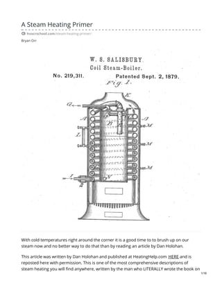
  • 1. Bryan Orr A Steam Heating Primer hvacrschool.com/steam-heating-primer/ With cold temperatures right around the corner it is a good time to to brush up on our steam now and no better way to do that than by reading an article by Dan Holohan. This article was written by Dan Holohan and published at HeatingHelp.com HERE and is reposted here with permission. This is one of the most comprehensive descriptions of steam heating you will find anywhere, written by the man who LITERALLY wrote the book on 1/16
  • 2. the subject. Enjoy! If you ask a dozen people what the proper operating pressure for a steam system is, you’ll probably get a dozen different answers. Most folks just follow “what they were taught”without giving much thought to the results. You see most steam systems run at ridiculously high pressures. As early as 1900, residential boiler manufacturers decided that no house heating steam system should operate at a pressure higher than two psi.They could make this statement because it’s latent heat, not steam pressure that does the actual heating work in a residential system. Latent heat is the energy we put into water to get it to change state from a liquid to a gas. In the early 1800s, an Englishman named Thomas Tredgold coined the term British thermal unit. He defined the Btu as the quantity of heat needed to raise the temperature of one cubic foot of water one degree Fahrenheit. After he died, folks changed the cubic foot to a pound (which is about a pint of water). They could do that because Mr. Tredgold was just making it up. Here’s more about this. For instance, suppose we had one pint of 32-degree water (water can exist as a solid or a liquid at 32 degrees. Did you know that?). If we wanted to raise that pint of water to 212 degrees, we would have to add about 180 Btu of heat. That would give us one pint of water, not steam, at 212 degrees (You see water can also exist as a liquid or gas at 212 degrees). But how do we get that pint of water to change state and become steam? We do it by adding a great deal of latent heat. You know the old saying, “A watched pot never boils?” Well, it’s certainly true because to make that pint of water turn into steam we have to add 970.3 Btu! Think of it. It only took 180 Btu to get that pint of water to rise from 32 degrees to 212 degrees. But it took more than five times the heat (970.3 Btu) to get it to move from 212 water to 212 steam. There was no change in temperature, but there sure was a change in the energy content. This energy is latent heat; it’s what heats the house. We get nearly all of it back when the steam condenses in the radiators. Steam can heat when it’s at zero-psi pressure. You see you don’t need a lot of pressure to heat the building. All you need is latent heat. To prove this is true, consider this: If you add only ten more Btu of latent heat per pound of steam to zero-psi steam, you’ll wind up with steam at ten psi. That ten additional Btu is insignificant when it comes to heating the building, but it can cause us many problems with the system. As you’ll see. 2/16
  • 3. The job of steam pressure is strictly to overcome the friction that steam meets as it works its way around the system. All we have to do is supply enough pressure back at the boiler to overcome the system piping’s friction. And the pressure you need is remarkably low because years ago, fitters sized pipe to offer very little resistance to steam flow. In fact, we measure this pressure in ounces per 100 feet of piping. This is why boiler manufacturers decided so many years ago that all you need is two psi to operate any house heating system. Raising the pressure higher than two psi will only cause you problems because steam is a gas. When you raise the pressure of a gas, you compress it. Just think about what happens when you put air in your car’s tires. And if you’d like to learn more about this, click HERE. Steam is a gas, just like air. When you compress it, it just naturally takes up less space. The amazing thing is that it also begins to move more slowly. It’s not as “large,” so It can afford to move more slowly. Strange as it may seem, it takes longer for high-pressure steam to get out to the radiators than it does for low-pressure steam. Also, high-pressure steam, since it’s more tightly packed, will call more water out of the boiler than low-pressure steam. This can lead to low-water problems back at the boiler. Steam travels across a system because of a subtle difference in pressure. Besides friction, the fire in the boiler and the condensing of the steam in the radiators also leads to a difference in pressure throughout the system. The fire creates the initial pressure. Since all the air vents are open, the inside of the piping system is at atmospheric pressure (which is 14.7 pound per square inch at sea level and different in other parts of the country). Steam begins to move from the higher pressure in the boiler to the lower pressure in the system. But as soon as it begins to move, it also begins to condense into water. This is because the pipes are cold and the steam is hot. When steam condenses into water it leaves a partial vacuum in its place. The condensing process causes this vacuum. This is a fine point you’ve probably never thought about. Steam occupies about 1,700 times the volume of water. That means that if you filled an eight-ounce glass with water and boiled it, you would have to have1,700 eight-ounce glasses available to catch the steam! A pint of water, once boiled, balloons out to fill a cubic yard! It’s like popcorn. This also means that when steam condenses in the radiators it will shrink to 1/1700th of the space it occupied as steam. What we’re left with (as long as the air vents remain closed) is a partial vacuum. This is good because it makes the steam travel to where you need it up in the radiators. This is why you don’t need pumps to move steam. All you need is a subtle difference in pressure. Now think about this. As the radiator heats, the condensing rate in that particular radiator will slow, right? In fact, it will eventually reach a point when very little steam is condensing. 3/16
  • 4. The metal will have reached steam temperature; the room will have reached the setting of the thermostat. It’s nature’s job to equalize temperature as well as pressure. And this is also a fine thing because it allows the steam to travel on to the next radiator down the line. The boiler’s job is simply to get steam (a gas) out to the last radiator before it turns into water (a liquid). If the boiler is too small for that task, the building will be partially hot and partially cold you’ll wind up with problems. You see when you’re working with steam heat, you’re really watching a race between the steam and the cold pipes. If the boiler is properly sized,the steam will win that race. This is why we size replacement steam boilers by measuring the radiators. As strange as it may seem, the heat loss of the building is not important. Only the “race” matters. We have to “fill that steel balloon” (the piping system) with steam before it can condense into water. As far as the replacement boiler is concerned, it doesn’t matter if the homeowner insulated every nook and cranny and replaced all the windows in the house. If the piping and radiators are there, you have to fill them with steam. It’s as simple as that. Don’t make the mistake of sizing the new boiler by taking the information off the old boiler. The person who did that sizing may have been wrong. Or, someone may have removed or added radiators over the years. Don’t take a chance; do it right. And keep in mind, too, that there’s a safety factor you have to add to the net radiation load to allow for the heating of the pipes. We call this the “pick-up” factor. Nowadays, we allow an additional 33%. Years ago, that safety factor was much larger, so when sizing a replacement steam boiler, the age of the system also matters. This “pick-up” factor is the difference between the Net Ratings (the actual radiation load) and the DOE Heating Capacity Rating (the radiators and the pipes). The firing rate of the boiler should match the DOE Heating Capacity rating of the system (that’s piping plus radiation). Let’s take a look at some of the other changes manufacturers have made to boilers in recent years. The importance of the Piping Around the Boiler As boilers became smaller, the piping around them became more and more important. Today’s replacement steam boiler contains much less water than the boilers of yesteryear. And yet the new boiler produces just as much steam as the old boiler! Modern oil burners and improved boiler design make this possible. But if you want that job to be successful you have to pay careful attention to the boiler manufacturer’s near-boiler piping specifications. Ignore them at your own risk! 4/16
  • 5. The purpose of the piping specification is to give you a boiler that delivers dry steam. Dry steam contains a great deal of latent heat. If you add even a little moisture to the steam by piping the boiler incorrectly (and letting the water leave the boiler with the steam), the latent heat content of the steam will suffer. The steam, in essence, will condense in the moisture before it has a chance to reach the radiators. In short, the steam will lose the “race” to that last radiator and parts of the building will be cold. And not only will the building heat unevenly, the fuel consumption will also increase because the pressuretrol will never reach its high limit. And to make things worse, you’ll probably also have water hammer. That’s the knocking in the pipes that people who don’t know any better think of as normal. Follow the boiler manufacturer’s instructions to the letter and you’ll avoid most of the common problems associated with steam. Here are a few of the things the boiler manufacturers will tell you to do: Allow at least 24 inches between the top of the boiler and the bottom of the steam header. Use full-size risers to the header. Pipe the system take-offs at a point between the last riser to the header and the equalizer. Pipe the swing joints into the header. Use a reducing elbow to connect the header to the equalizer. You’ll probably also see a section on how to clean the boiler after you’ve worked on it. There’s really no way around this; all steam boilers must be cleaned after they’re installed. You don’t necessarily have to do it immediately, but you do have to do it. It often pays to let the system run for a few days before you go back to give it a good cleaning. Waiting a few days gives the oil and dirt a chance to settle on the surface of the water. There are many opinions on the best way to clean a steam boiler. One of the oldest ways is to dissolve a pound of tri-sodium phosphate (TSP) and a pound of caustic soda (lye) in water and pour it into the boiler. Let it cook for a few hours and then drain the boiler. If you can’t buy TSP in your town, try a commercial soap called MEX. It works well and will not damage the rubber gaskets found in some boilers. However, before you clean any boiler, check the manufacturer’s instructions for their recommendations. Skimming the boiler is the best way to remove surface oil. You’ll know there’s oil in the boiler if you see any moisture at all in the gauge glass above the water line. Many technicians are tricked into believing the water is clean just because it appears to be clear in the gauge glass. But they’re in for a surprise because oil can be colorless in boiler water. The part of the gauge glass above the water line should be bone dry. It should look like someone just ran a dishtowel through it. 5/16
  • 6. If you have a surging water line and there’s moisture in the gauge glass try cold skimming the boiler. You do this by opening a horizontal tapping above the water line and installing a six-inch nipple. Open the feed-water line slowly until the water level rises to the center of the nipple and spills out. Don’t be in a hurry. If you rush, you’ll be skimming from below the surface of the water and accomplishing nothing. Let the water run slowly from the skim port for several hours. Check it periodically by taking a sample of the water and boiling it on the customer’s stove in a small pot. If there’s oil in the water, the water will foam when it boils. Keep skimming and checking until your sample boils like tap water; that’s when you know you’re done. Remove the nipple and start the boiler. In most cases, your surging problems will become just a bad memory. Skimming from the top of the boiler doesn’t work as well because the rising water will cling to the metal before it has a chance to get out of the boiler. Draining from the bottom of the boiler doesn’t work as well as horizontal skimming either for the same reason. Firing a small boiler while skimming is ineffective because the surface oil will be emulsified in the water. Just think about what happens to the oil you add to a pot of boiling water before you drop in that pound of spaghetti. Oil doesn’t stay on the surface when the water is boiling. This is especially true in a highly efficient, low-water-content boiler. Cold, horizontal skimming works pretty well most of the time, if the boiler’s been up and running for a while. Let’s take a look at several different types of steam systems. One-pipe Steam One-pipe steam takes its name from the single pipe that connects each radiator to the steam main. Both steam and condensate travel in this pipe, but in opposite directions. This is what often makes one-pipe steam so difficult to manage. When steam and condensate travel in opposite directions (what we call “counterflow”) you have to pay close attention to the size and pitch of the pipes. For instance, when steam and condensate move in the same direction (that’s “parallel flow”) the pitch should be at least one inch in twenty feet. When there is counterflow, however, the pitch must be at least one inch in ten feet. See? It doubles. The exception to this is when you have a horizontal run-out to a radiator riser. Here, the pitch should be at least one-inch inch per foot. Where you can’t get this pitch, (or when the horizontal run-out is longer than eight feet) you have to go to the next- size pipe. 6/16
  • 7. The rules are fairly simple, but few people take the time to learn them. That’s why you wind up with so many radiators that bang and so many air vents that spit. If you’re adding or removing radiators, get some advice from a reputable supplier of steam specialties. They’ll be able to help you out with the pipe sizing and pitch. Let’s take a look at the basic controls on a one-pipe (and a two-pipe) system. The pressuretrol determines the operating range of the boiler during the heating cycle. It’s important to understand that a heating boiler doesn’t make steam all the time. It only does that when the thermostat clicks on. During a call for heat, the boiler will cycle up to the cut- out setting of the pressuretrol. At that point, the pressuretrol will shut off the burner. Some pressuretrols show the cut-out setting as “Differential.” Usually, you’ll add that “Differential” to the “Cut-In” setting to get the”Cut-Out” setting. Be careful, though, because some pressuretrols show”Differential” as a number to be subtracted from the cut-out setting.Take a few minutes to read the instructions and think about what the manufacturer is telling you. When the pressuretrol reaches its cut-out setting, steam will be moving out into the system and condensing in the pipes. This condensing process will cause an overall drop in system pressure. When the system cycles down to the cut-in pressuretrol setting, the pressuretrol will re-start the burner, as long as the thermostat is still calling for heat. If the thermostat isn’t calling for heat, the burner will remain off, and the steam pressure will drop to zero (atmospheric pressure). Usually, you should set the pressuretrol to turn the burner on at one-half psi and off at the lowest possible pressure required to heat the furthest radiator. If that pressure winds up being more than 2 psi, something is probably wrong. Most likely, the air vents aren’t working properly. Years ago, fitters used vaporstats to control the boiler. These are like pressuretrols, but they’re much more sensitive. A vaporstat measures pressure in ounces. They’re still available today, but they’re more expensive than pressuretrols. Nevertheless, along with quality air vents, a vaporstat is probably the best investment you can make. You see when it comes to steam, low pressure is the key to success. If you’re concerned about the burner because it’s short-cycling, look to the air vents, not the pressuretrol. Main vents are the key here. Get rid of the air and the building should heat without short cycling. Commercial boilers also require a manual-reset, high-limit pressuretrol to shutoff the burner should the pressure rise too high. Make sure you instal this with the operating 7/16
  • 8. pressuretrol, but not on the same pigtail. Speaking of which, you pipe the pressuretrol to a steam pigtail so you’ll have a water seal between the control and the boiler. The water protects the control from the steam temperature and extends its life. Obviously, you should not have a valve between the boiler and the pressuretrol. If the pigtail clogs (which it will!) replace it with a new one. If you’re burner is short cycling, it may be because the pigtail is clogged. Check it out. The relief valve protects the boiler against a runaway fire. On space-heating steam boilers the relief valve is set to pop at 15 psi. This is the limit for any low-pressure boiler. The relief valve should be rated by the American Society of Mechanical Engineers (ASME, for short), and you should size it for the maximum load of the boiler. For safety, pipe it to a drain, or to within a few inches of the floor. It’s not a good idea to pipe the relief valve to the outdoors because, should it pop off, water will be held in the pipe by vacuum, much as water is held in a straw when you put your finger over one end. During the winter, the trapped water in a relief line that’s piped to the outdoors can freeze and block the escaping steam as surely as a pipe plug will. That’s dangerous! If you must pipe the relief valve to the outside, use a vacuum breaker at the discharge of the valve. This will allow the water to drain the water from the line after the relief valve has popped. It’s best to avoid this altogether if you can, though. And naturally, there should never be any valves between the relief valve and the boiler or the relief valve and the drain line. The low-water cutoff is required by code. Its job is to shut off the burner should the water level fall to an unsafe point. The boiler manufacturer determines this level, but it’s usually within one-half inch of the bottom of the gauge glass. The low-water cutoff can be a float-type or a probe-type. Probe-type low-water cutoffs are becoming very common on low-water-content boilers because these cutoffs have timing devices to prevent nuisance shut-downs should the boiler water surge. Probe-type cutoffs send a low-voltage charge through the water to ground on the boiler’s metal. Don’t use a probe control without first getting the boiler manufacturer’s recommendations as to where they want it installed. Float-type cutoffs mount directly on the gauge glass of the boiler and sense the movement of the water line mechanically. The low-water cutoff manufacturer determines where the cutoff belongs. You should never tamper with these settings. Some installers try to make the boiler more “automatic” by raising the low water cutoff so that it covers the domestic water coil all year long.This, they think, will save the homeowner the trouble of raising the level by hand during the summer. But it’s a bad idea because it 8/16
  • 9. also creates a “normal” water line that’s several inches too high. It brings the boiler water too close to the steam outlet and drives water up into the system. Before you know it, you have more problems than you bargained for. Save yourself a headache and have the customer cover the tankless coil by hand once a year. The gauge glass is your way of knowing where the water is in the boiler. Expect to see some minor movement in the water line. Anything between a half- and three-quarters of an inch of up-and-down movement is normal. When the boiler is off, the “normal” water line is the center of the gauge glass. When the system is running, the “normal” water line is near the bottom of the gauge glass. That’s because the water, in the form of steam and condensate, is out in the system. When the burner shuts down, the level will return to the center of the gauge glass again. Don’t try to keep the water in the center of the glass when the system is running because, obviously, this will cause the boiler to flood when the condensate finally returns on the down cycle. Again, this is why you shouldn’t tamper with the low-water cutoff level. The automatic water feeder (if you’re using one) is there to maintain a safe minimum water line. It is not there to maintain a “normal” water line when the boiler is off. A water feeder will protect the system against freeze-ups if the people are away in the winter and, say, an underground return should spring a leak. Without the feeder, the low- water cutoff would shut down the burner and the house would freeze up. So, while it’s not essential to the system’s operation, you can consider an automatic water feeder a useful back-up safety device. In addition, a feeder will provide some convenience in an old system that’s prone to leaks. The feeder will maintain an operating water level rather than have the burner shutting down daily on low water. If the customer doesn’t want his leaking, buried returns replaced, an automatic feeder makes a lot of sense. But naturally, a great deal of fresh feed water can also harm the boiler through oxygen corrosion. Think about this when you’re advising the customer. Give them the facts and their options. Then, leave the decision to them. Let’s take a minute now to define some terms. A wet return is any pipe that’s below the boiler water line. A dry return is any pipe that’s above the water line. The header is the large horizontal pipe directly above the boiler. You have to size it to carry the entire steam load of the boiler. Nowadays, the boiler manufacturer will often oversize the header so it acts as a point of low velocity. That gives the steam a place where it can 9/16
  • 10. slow down and dry out before it heads out into the system piping. Always check the boiler manufacturer’s requirement on header size before you install a replacement steam boiler. You’ll often find that the old header is too small for the new boiler. Risers are the pipes between the boiler and the header. They must be the full size of the boiler tapping. Don’t reduce them because you’ll cause the steam to move too fast. When that happens, the steam will pull some of the water out of the boiler and throw it into the system piping. Many of the newer boilers call for two (or three!) risers to the header. The older boiler may not have needed as many. If you go with the old piping and ignore the manufacturer’s instructions for the new boiler, the new boiler’s water line might wind up tilting at a severe angle. That can lead to very wet steam and, in many cases, a broken boiler because the flame will be licking at the boiler’s exposed crown. Without water to carry off the heat, a boiler can crack. If the boiler has more than one outlet, it’s also important to remember to pipe the headers with swing joints. If you don’t, the boiler sections can be split wide open like an accordion when the horizontal header heats and expands. If you have such a boiler with more than one outlet (and swing joints) you shouldn’t use copper instead of steel for your header. This is because copper expands twice as much as steel. That can cause the soldered joints to come apart and leave your customer with steam leaks. Consider, too, that when you use copper in a steam system there will be more corrosion than normal because of the dissimilar metals. Copper, steel, and iron lead to corrosion at the places where they come together. Take-offs are the pipes connecting the header to the system. You probably won’t be changing these. The original installer sized them to handle the connected load. Sometimes, someone adds radiation to the existing take-off, and you should watch for this because it can cause you service problems. The take-off might not be able to carry the additional heat on a cold day. Any reputable manufacturer of steam-heating equipment will be able to check the size of the take-off against the connected load and advise you. The boiler manufacturer determines the size of the equalizer. Its job is to return any water that slips out of the boiler with the steam, and also to balance the pressure between the supply and the return sides of the boiler. Without a properly sized equalizer, water can back out of the boiler. Never pipe a steam take-off over the equalizer. The steam’s velocity can create a pressure drop in the equalizer that will lift the water up, causing a corresponding drop in the boiler’s water line. 10/16
  • 11. In 1919, the Hartford Steam Boiler Insurance and Inspection Company invented the Hartford Loop. Its job was to prevent water from leaving the boiler, should a return line spring a leak. Here’s more about the Hartford Loop. The connection between the loop and the equalizer must be made with a close nipple to prevent water hammer. This is because steam is forming in the Loop connection. Returning condensate can cause this steam to rapidly condense and shrink to 1/1700th its steam volume. The water rushes into fill the void. As the condensate slams against the back of the tee, you wind up with water hammer in the return. The dimension labeled “A” in the diagram represents the distance you have to maintain between the center of the gauge glass and the bottom of the lowest dry return in the system. In one-pipe systems that have DOE Heating Capacities greater than 100,000 BTUs, “Dimension A” must not be less than 28 inches. “Dimension A” provides the force that puts the condensate back in the boiler.Without it, water will back up into the horizontal piping and shut off the take-offs to the radiators. The house will heat very slowly (if at all), and certainly very unevenly. You’ll probably also have water hammer. And this is also why you don’t see main vents on many of jobs. They’re installed improperly and get damaged on the first few cycles. That’s a shame because main vents are the key to good one-pipe steam operation. If you’re using good main vents near the ends of every main, steam will travel very quickly to every radiator in the building. Vent large radiators quickly and small radiators slowly no matter where they are in the building. Focus on the air content of the radiator rather than its location in the building.If your main vents are working, steam will arrive at each radiator at about the same time. Baseboard over three feet long has no place in a one-pipe steam system. In most cases, you can never get the pitch or size you need to keep the air vent from spitting water up at the ceiling. If you must use baseboard, connect it with two pipes, vent the outlet side, and drip the return pipe immediately into a wet return. Do not use a steam trap; just drip it into a wet return. Pitch the baseboard run toward the return as much as you can. Let’s take a look at another type of system now. Two-pipe Steam Like one-pipe, two-pipe steam takes its name from the number of connections you’ll find at the radiator. As heating jobs got larger in the old days, fitters found it made good sense to have just steam in one pipe and just condensate in the other. That way, each pipe could be smaller and the pitch of the pipes became less crucial because everything was moving in the 11/16
  • 12. same direction. Ina two-pipe steam system, the steam connection is usually at the top of the radiator; the condensate connection is at the bottom on the opposite side, but this doesn’t always have to be the way. You can also have the inlet and outlet at the bottom of the radiator at opposite ends. Or you can have the inlet at the top, and the outlet at the bottom, on the same side of the radiator. At the turn of the century there was a type of steam system called the two-pipe, air-vent system. This system had two pipes (and two supply valves) at opposite ends of the bottom of the radiator. Since this system didn’t use steam traps (they hadn’t invented them yet!), both pipes carried steam. It worked because of the air vents. One pipe was always larger than the other. The larger pipe was always on the inlet side of the radiator. When the steam traveled through the system, it favored the larger pipe because that’s where the least resistance to flow was. But this was an expensive system to install because there were twice as many pipes as a one-pipe system, and it offered an advantage only when the radiators were very large. With a large radiator, you have a lot of condensate flowing backward down the one-pipe supply line. That can create water hammer. The two-pipe steam system died an early death and has been obsolete for many years. But there are still many of them around. They were popular in municipal-type buildings such as schools and courthouses. If you see two supply valves at the bottom of the radiator, you probably have one of these old systems. Be careful. This system is easily confused with true two-pipe steam. However, it works differently and can cause quite a few problems should you make certain piping changes to the system. True two-pipe steam uses thermostatic steam traps on the radiators. The steam trap has three jobs It opens to let air pass through the radiator and into the return piping. Air is a great insulator. If left in the radiator, you’ll have a cold room. Also, when water boils, it releases a great deal of carbon dioxide because of carbonates and bicarbonates that are common to freshwater. This carbon dioxide will travel through the system and mix with condensate to form a mildly corrosive carbonic acid. Naturally, this acid is harmful to the radiators and also to the returns. This is another reason why good main air vents are so important to steam systems. You have to get rid of that carbon dioxide before it mixes with the condensate. So steam traps are actually air vents as well! The second job of the steam trap is to close when steam reaches it. Radiator steam traps have thermostatic bellows. Manufacturers fill these bellows with a mixture of alcohol and water. They use alcohol because it boils at 170 degrees at atmospheric pressure (water boils at212). The alcohol/water mixture is usually set to boil at about 180degrees. When steam reaches the radiator trap, the alcohol “flashes”and expands the bellows. There’s a 12/16
  • 13. pointed metal rod, called a “pin,”on the bottom of the bellows. When the bellows expands, it pushes this pin down into the trap’s seat. The trap is now closed and no steam can escape. With nowhere to go, the steam condenses and gives up its latent heat to the room. Should the bellows fail a good deal of the steam will pass into the returns and heat the insides of the building’s walls instead of the rooms where the people are. This is wasteful, noisy (water hammer) and destructive to the condensate pump, if you’re using one. But a failed trap is hard to spot because the radiator will continue to heat. It won’t look any different from the outside, The third job of the trap is to open once the condensate has cooled. The condensate will pass through the trap and flow downhill to the boiler. Most radiator trap elements have a life span of about three years. This is because the element flexes about 155,000 times per heating season. This near-constant movement, combined with water hammer, is what kills the elements. Unfortunately, most people check traps about once every 30 years! You can check radiator traps with a temperature-sensitive crayon called a TempilStick or with a temperature probe. There should be about a 20-degree difference across an operating trap. The problem is that if just one trap fails, the steam passing into the returns can trick you into thinking a nearby trap has also failed. It helps to check the system backward, starting with a large return and working up toward the branches. This should reveal problem areas. Then it’s just a matter of isolating radiators and checking them. True, it’s time-consuming, but it’s also necessary. Steam traps also have a curious effect on the system’s returns. Because they close to steam, traps prevent steam from getting into the returns. Remember what we said about the one- pipe system? Water returned to the boiler because of the static weight of the water in “Dimension A” and the “leftover” steam pressure at the end of the main. With two-pipe, you no longer have “leftover” steam pressure to put the condensate back in the boiler. This is because of the traps. This means that the only force you can depend on is the static height in “Dimension A.” With two-pipe steam, “Dimension A” must be at least 30 inches for every pound of pressure in the boiler. In other words, if you fire the boiler at 2psi, you’ll need 60 inches of height between the center of the gauge glass and the bottom of the lowest steam main. If you fire 5 psi, you’ll need 12-1/2 feet between those two points! It’s another good reason to keep that steam pressures low, isn’t it? 13/16
  • 14. This is why you’ll often see condensate pumps being used on two-pipe steam systems. The pump provides the pressure needed to put the condensate back in the boiler because the basement isn’t deep enough to the returning condensate enough static weight. A condensate pump is the low point in the system. Everything must flow downhill to it. If any part of the system piping dips below the condensate pump inlet, you’ll have water hammer shortly after the system first starts up. A condensate pump has a receiver made of either steel or cast-iron(cast-iron lasts much longer than steel because condensate is corrosive). This receiver is nothing more than a gathering chamber for returning condensate. It’s vented to the atmosphere because, for the most part, condensate receivers aren’t rated to withstand any pressure. If you plug the receiver vent, the receiver can explode! Inside the receiver is an electrical float switch. This switch turns the pump on when the water level inside the receiver rises, and off when it falls. On the discharge side of the pump you’ll find a check valve (to keep the boiler water in the boiler) and a throttling valve. The throttling valve is there to slow the pump down. You see most condensate pumps will discharge at 20-psi pressure. That’s too high for most heating applications (It’s not too high for commercial applications, however). The throttling valve will stop the check valve from chattering by adding resistance to the pump’s pressure. You just crank the valve down until the noise stops. A condensate pump has no way of knowing if the boiler it serves needs water or not. When it fills, it dumps; it’s as simple as that. Because of this, boiler-feed pumps are sometimes used in place of condensate pumps. This is especially true with modern, low-water-content boiler. A boiler-feed pump is different because a float switch located on the boiler, not in the pump’s receiver, controls the pump. With a boiler-feed pump, the pump can come on only if the boiler needs water. The receiver in the boiler-feed pump is also much larger than the condensate pump’s receiver. This oversized receiver gives the condensate a place to wait until the boiler needs it. Be careful when you replace an old boiler on a two-pipe system with a new boiler. You may find that the old condensate pump isn’t compatible with the new boiler. You may need a boiler-feed pump. 14/16
  • 15. Hanging a storage tank on the side of the boiler is no substitute for a boiler-feed pump. First of all, all the reserve water would have to be located within the three inches, or so, of boiler operating range. This leads to very long and very narrow tanks. But more important, that additional water would have to be brought to steam temperature on each firing cycle. The tank will typically contain about125% of the water in the boiler! This kills the overall operating efficiency of the boiler and can cause the customer to use more fuel than he would have with his old boiler. When you’re using a condensate or boiler-feed pump, or when the two-pipe system has dry returns, you’ll find float-and-thermostatic (F&T) traps at the ends of the steam mains. These larger traps keep steam from reaching through to the dry return piping. The thermostat in the F&T trap is there strictly to pass air to the vent on the condensate pump. The condensate passes through the trap by lifting a float. This float is very similar to the ballcock in a toilet tank. The trap is normally closed. Steam can’t pass through the trap when the ball is down because the lever attached to the ball is also attached to the trap’s pin, and that pin is firmly seated in the trap’s outlet. Since steam can’t escape, it will condense. It’s this condensing steam that eventually raises the float ball and opens the trap. When the trap opens, the higher pressure on the trap’s inlet pushes the condensate through the trap and into the return line. When the trap goes dry, the ball drops the pin back into the seat and keeps the steam from escaping. Because the trap is normally closed, it, too, will have an effect on the returning condensate. You’ll need 30 inches of height between the trap and the center of the gauge glass for every pound of pressure in the boiler. That is, of course, unless you have a condensate or boiler- feed pump supplying the return pressure. This is a good place to mention that motorized zone valves on the steam takeoffs have the same effect on returning condensate as traps. You should never use them on a steam system unless you also use a condensate or boiler-feed pump, and F&T traps. Since F&T traps are mechanical devices, they’re not sensitive to temperature (thermostatic radiator traps are sensitive to temperature).There is no noticeable drop in temperature from one side to the other of an F&T trap. They discharge water at the same temperature as steam. Remember what we said about steam in the section on “How Steam Heats?” It can be either a liquid or a gas at the same temperature, right? The difference between the two is latent heat, and you can’t measure latent heat with a thermometer. This is where things get a bit tricky because you can’t check an F&T trap with a TempilStick (908-757-8300) or a temperature probe. There’s no difference in temperature across an F&T trap, even when the trap is operating! 15/16
  • 16. The way to check F&T traps is to open a union or a valve on the discharge side and look at what comes out. If the trap isn’t operating properly, there will be several inches of invisible steam and then a plume of vapor. If the trap is operating, you will see only vapor and water. This is why it’s a good idea to install new F&T traps with a drain valve and a shut-off valve on the discharge side. These two valves make troubleshooting very easy. Most F&T traps fail because they are oversized. You should never size an F&T trap to match the line size. This causes the seat to withdraw and leak in no time at all. Trap sizing isn’t difficult, but you do need to know how much condensate will be passing through the trap and at what pressures (both supply pressure and back pressure). Seek the advice of a reputable steam trap manufacturer if you’re not sure what to do. In recent years, many older, two-pipe steam systems have been retrofitted with non-electric thermostatic radiator valves. These valves sense the air temperature in the room and open or close the steam supply to the radiator. They’re installed in place of the supply valve. Because no condensate travels down the supply pipe in a two-pipe system, you can throttle the supply valve without getting water hammer. These thermostatic radiator valves make the system more efficient because they prevent the radiator from overheating. They also compensate for outside heat sources such as sunlight, machinery and people. Take your time and always keep in mind that all steam systems operate on the simple law of pressure differential. High pressure will always move toward low pressure. And those pressures are usually very subtle. It’s as simple as that! Want to learn more? Check out Dan Holohan’s book The Lost Art of Steam Heating. See more at: https://heatinghelp.com/systems-help-center/a-steam-heating- primer/#sthash.UsaILjyf.dpuf P.S. – Big thanks to Erin Holohan for allowing me to repost this. I had the privilege of meeting Erin at the AHR Expo last month and she was very kind and generous with her time in speaking with me. 16/16