SlideShare a Scribd company logo
1 of 8
Download to read offline
Page1
The Interface Solution Experts • www.miinet.com/moorehawke
Introduction to Fieldbus
Fieldbus is simple. So simple, you’ll wonder what all the
fuss is all about. In this article, we’ll stick to the two
basic fieldbuses used in process control: PROFIBUS PA
and FOUNDATION fieldbus™ H1. We’ll cover how
fieldbus works, show how to connect instruments, and
explain why—in most cases—you can’t connect all 32
instruments on a single fieldbus segment as all the
advertising claims.
We will also talk about the differences between
PROFIBUS and FOUNDATION fieldbus, FISCO vs. Entity
intrinsically-safe fieldbus systems, installing redundant
segments, and EDDL vs. FDT.
How Fieldbus Works
In analog controls systems, instruments produce a
4-20mA output signal that travels all the way from the
remote distillation column, tank or process unit to the
control room, marshalling rack, remote I/O concentrator
or RTU over twisted pair cables. Similarly, 4-20mA
control signals travel from the control system to valve
actuators, pumps and other control devices. Hundreds,
sometimes thousands, of cables snake their way through
cable trays, termination racks, cabinets, enclosures and
conduit (Figure 1).
The availability of low cost, powerful processors suitable
for field instrumentation now opens the way to remove the
bulk of these cables and, at the same time, enhance
data available from the plant.
Instead of running individual cables, fieldbus allows
multiple instruments to use a single cable, called a
Figure 1. Traditional 4-20mA field wiring often results in a rat’s
nest of wires, cables and terminations.
“trunk” or a “segment,” (Figure 2); each instrument
connects to the cable as a “drop.” Instruments, of
course, must have a fieldbus interface to connect to the
segment, and some sort of software running to provide
the fieldbus communications.
Afieldbus trunk or segment—either FOUNDATION
fieldbus H1 or PROFIBUS PA—is a single twisted pair
wire carrying both a digital signal and DC power that
connects up to 32 fieldbus devices (temperature, flow,
level and pressure transmitters, smart valves, actuators,
etc.) to a DCS or similar control system. Most devices
are two-wire bus-powered units requiring 10 to 20mA, but
it is also possible to have 4-wire fieldbus devices,
typically where a device has a particularly high current
draw.
The fieldbus segment begins at an interface device at the
control system. On a FOUNDATION fieldbus H1 (FF)
system, the interface is called an H1 card; on a
PROFIBUS PA system (PA), it is a PROFIBUS DP/PA
segment coupler. In terms of signal wiring and power
requirements for the segment, FF and PA are identical:
• Minimum device operating voltage of 9V
• Maximum bus voltage of 32V
• Maximum cable length of 1900m
(shielded twisted pair)
The DC power required by the bus is normally
sourced through a fieldbus power supply or “power
conditioner” which prevents the high frequency
communications signal from being shorted out by the DC
voltage regulators. Typical power conditioners make 350
to 500mA available on the bus and usually incorporate
isolation to prevent segment-to-segment cross talk. For
PA, the “segment coupler” usually incorporates the power
conditioning component. In FF segments, the power
conditioners are separate from the H1 interface card and
are often installed in redundant pairs to improve the
overall reliability. Figure 3 shows a typical fieldbus
segment.
When calculating how many devices can fit on a fieldbus
segment, a user must take into account the maximum
current requirement of each device, the length of the
segment (because of voltage drops along the cable), and
other factors. The calculation is a simple Ohm’s law
problem, with the aim of showing that at least 9V can be
delivered at the farthest end of the segment, after taking
into account all the voltage drops from the total segment
current. For example, driving 16 devices at 20mA each
requires 320mA, so if the segment is based on 18AWG
cable (50 Ohms/km/loop) with a 25V power conditioner,
Figure 2. A fieldbus
installation substantially
simplifies wiring.
Photo Credit: Genzyme
Page2
The Interface Solution Experts • www.miinet.com/moorehawke
Introduction to Fieldbus
the maximum cable length is 1000m to guarantee 9V at
the end. Note that many users also specify a safety
margin on top of the 9V minimum operating voltage, to
allow for unexpected current loads and adding additional
devices in the future.
Connecting Instruments
As noted, each fieldbus device connects to the segment
in parallel, via a “drop” on the fieldbus segment called a
spur. The simplest spur connection is a “T.” The problem
with simple “T” connections (Figure 4), is that if any one of
the devices or cables short out, it takes down the entire
segment. A short can occur during field maintenance of
an instrument, from an accident in the field, corrosion
causing electrical problems, or a host of other
possibilities. Short-circuit protection is therefore a
requirement for proper fieldbus implementation.
Figure 3. A fieldbus segment starts with an H1 interface card and a power supply for FOUNDATION fieldbus or a segment coupler for
PROFIBUS. Up to 32 devices can be supported on a single segment. The boxes with a “T” in them indicate the location of the segment
terminators.
1900m
Segment LengthTerminator
H1 Card
or
DP/PA
Segment
Coupler
Fieldbus Host
Fieldbus Power
Supply
120m
Fieldbus cable can be used but,
in general, H1 and PA systems can
run on standard instrument grade
twisted pair cable
Maximum number of field
devices per segment is 32
Terminator
Another way to connect fieldbus devices is via junction
boxes specifically designed for fieldbus, often referred to
as “device couplers”—such as the MooreHawke™ TG200
TRUNKGUARD™ (Figure 5)—that allow multiple fieldbus
devices to connect at one location. Typically, users will
install a device coupler in a field enclosure, and connect
nearby instruments to it. The fieldbus cable may continue
onward to another device coupler. A multi-instrument
segment may have several device couplers.
Two basic types of electronic spur short-circuit protection
are used in device couplers: “current limiting” and “fold-
back.” Both prevent a spur fault from shorting out the
segment and both auto-reset back to normal on removal
of the fault.
The current-limiting technique limits the amount of power
the short circuit can draw to between 40 and 60mA
(vendor dependent) but it also holds that fault on the
segment continuously. Although this design protects the
segment from the initial short, the additional current draw
can deprive other instruments on the segment of power,
overload the segment power supply, and possibly cause
catastrophic failures on the segment.
When a short circuit deprives other instruments of power,
some may “drop off” the segment because they do not
have enough power to operate properly. Consequently,
when current limiting protection is used in a device
coupler, many end users allow a safety margin. That is,
Figure 4. “T” configurations are the simplest fieldbus connection.
However, if one device fails or short-circuits, it “takes down” the
entire segment.
Page3
The Interface Solution Experts • www.miinet.com/moorehawke
Introduction to Fieldbus
they do not install as many instruments as the segment
can theoretically power; instead, they leave a certain
number of spurs empty.
For example, if a user wants the segment to be able to
keep working with two failures—which can draw up to
120mA of current—the segment calculations must
assume a maximum current availability of 350mA minus
120mA for the faults, or 230mA.
T
Fieldbus DC
Power Conditioner,
350-500mA
(Not Required for PA Systems)
T
DC Power
Input
Fieldbus
Termination
FOUNDATION Fieldbus
or PROFIBUS PA
Network (Twisted Wire Pair)
1,900m Maximum
Segment Length
120m
Maximum
Spur Length
Automatic
Segment
Termination
Fieldbus
Devices
Fieldbus
Trunk
Out
TG200 Fieldbus
Device Coupler
TG200 Fieldbus
Device Coupler
Fieldbus
Trunk In
Fieldbus
Trunk Out
Fieldbus
Trunk In
"Fold-Back"
Short Circuit
Protection
with Auto Reset
H1/PA Interface
Figure 5. A device coupler permits multiple instruments to be
connected to a fieldbus segment. Each “spur” has short-circuit
protection, so it cannot harm the entire segment. More than one
device coupler can be used in a segment.
Instead of theoretically being able to power 32 devices
that draw 10mA each, the segment is now only able to
support 23 such devices. In practice, some users are
wary of relying on current limiting couplers, and most limit
each segment to only 16 devices to prevent large-scale
segment failures.
The fold-back technique, as used in MooreHawke’s
TRUNKGUARD Device Couplers, disconnects the shorted
spur from the segment, thus preventing loss of an entire
segment. The fold-back technique has a logic circuit on
each spur (Figure 6) that detects a short in an instrument
or spur, disconnects that spur from the segment, and
illuminates a red LED that can be seen by maintenance
personnel.
With fold-back device couplers, users no longer have to
worry about spur failures and can have confidence about
placing more devices on fieldbus segments. Since the
cost of H1 cards ($2,500) and other segment hardware
can be cost-prohibitive, being able to place more devices
on a segment can save users a considerable amount.
Segment Termination
Every fieldbus segment must be terminated at both ends
for proper communication. If a segment is not terminated
properly, communications errors from signal reflections
may occur. Most device couplers use manual on/off DIP
switches to terminate couplers. In a segment, the last
device coupler should contain the terminator, and all
couplers between the last coupler and the H1 card should
have their terminator switches set to off.
The boxes with a “T” in Figure 3 and 5 illustrate where a
typical segment is terminated properly.
A frequent commissioning problem during startup is
determining that terminators are correctly located. During
Logic
FAULT
Device
Trunk
Figure 6. Fold-back short circuit protection has logic that detects
a short, removes the shorted circuit from the segment, and lights an
LED. This prevents a short from affecting the segment.
Page4
The Interface Solution Experts • www.miinet.com/moorehawke
Introduction to Fieldbus
A “voting scheme” is needed because most control
systems cannot tell when a fieldbus segment fails. They
can only detect if the H1 or DP/PA interface itself fails, or
if a particular fieldbus device fails. If the interface remains
powered, the control system has to determine, by
analyzing instrument signals (or the lack thereof), that the
entire segment has failed.
Needless to say, such redundancy schemes are
expensive, complex, and can be hard to maintain. A
catastrophic process failure could result while the control
system is determining what’s wrong.
The prospect of losing an entire critical segment often
makes end users wary of fieldbus. If a segment contains
“process-critical” instruments, they generally limit the
number of instruments per segment to only a few, or
spread critical instruments over multiple redundant
segments.
MooreHawke has solved the redundancy problem for
FOUNDATION fieldbus systems.
MooreHawke’s TRUNKSAFE™ Fault-Tolerant Fieldbus
System provides a highly-reliable way to maintain
continuous communications between field devices and a
DCS in the event of any single point failure (such as open-
or short-circuit) on a FOUNDATION fieldbus segment.
Figure 7. Some fieldbus redundancy techniques require complete
duplication of the segment; in some cases, this means duplicate
field instruments. When a segment fails, logic in the DCS
determines that a failure has occurred, and switches from one H1
card to the other.
Device Coupler
Fieldbus
Instruments
Device Coupler
Distributed Process Control System
installation of the fieldbus system, the DIP termination
switches sometimes are set incorrectly, creating
problems during startup. The instruments can behave
erratically, drop off the segment mysteriously, and
generally raise havoc—all because the terminations are
not set properly.
Diagnosing the problem often requires physically
examining each device coupler to determine if the
switches are set properly throughout the segment.
Automatic Segment Termination, as found in
TRUNKGUARD Device Couplers, simplifies
commissioning and startup. It automatically activates
when the device coupler determines that it is the last
fieldbus device coupler in the segment; if it is, it
terminates the segment correctly. If it is not the last
device, it does not terminate the segment, since the
downstream device coupler will assume that
responsibility. No action—such as setting DIP
switches—is necessary by the installation person to
terminate a segment properly.
If a device coupler is disconnected from the segment
accidentally or for maintenance, theAutomatic Segment
Termination detects the change, and terminates the
segment at the proper device coupler. This allows the
remaining devices on the segment to continue operation.
Redundant Fieldbuses
Fieldbus has one major problem: all communications and
power are dependent upon a single twisted pair trunk
cable. If the trunk cable fails, it can “take down” all the
devices on the segment at one time. Not only is the
fieldbus segment lost to the control system, devices on
the segment can no longer talk to each other. Although
fieldbus instruments can continue to operate if the control
system fails, any cable fault (open or short-circuit) could
render the entire segment inoperable.
This problem is especially serious on plant-critical
segments, where the failure of a segment may adversely
affect plant or process applications, lead to costly
process shutdowns, cause a hazardous condition, or
release materials into the environment.
No provision is made within either fieldbus standard for
redundant segment communications. Various fieldbus
vendors, including major process control companies, have
developed redundant fieldbus schemes that involve
complete duplication of all equipment—including H1 or
DP/PAinterfaces, power supplies, fieldbus cables,
device couplers, and some critical fieldbus instruments
(Figure 7)—plus complex software voting schemes.
Page5
The Interface Solution Experts • www.miinet.com/moorehawke
Introduction to Fieldbus
SAFE AREASAFE AREA
H1 Interface
Fieldbus Power
Supply
DCS
I.S.
Barrier
Fieldbus
Terminator
FOUNDATION Fieldbus Network
(Twisted Wire Pair)
Fieldbus
Terminator
Fieldbus Devices
T
T
HAZARDOUS AREAHAZARDOUS AREA
TRUNKSAFE (Figure 8), consists of dual, redundant
TPS200Advanced Fieldbus Power Conditioners (one for
each leg of the segment), two fieldbus cables, and a
TRUNKSAFE TS200 Device Coupler.
The power conditioners are located on DIN carriers for up
to four segments at a time and the device couplers
accommodate six or 10 fieldbus instruments.
In a typical TRUNKSAFE application, two redundant H1
interface cards are connected to two legs of a fieldbus
segment, and wired out into the field. The power on each
leg is properly conditioned by the TRUNKSAFE Power
Conditioner, and run to the TRUNKSAFE Device Coupler,
which are connected to multiple fieldbus devices. The
installer routes the fieldbus cables separately, so that the
same incident (a careless forklift driver, for example) does
not take both cables out at the same time.
If a fault occurs on either cable, the power conditioner on
the affected leg immediately cuts power to that leg and its
H1 interface, which forces the DCS to switch to the
alternate H1 card. The device couplers can be driven by
either trunk; if one trunk loses power, the device coupler
Figure 8. The TRUNKSAFE Fault-Tolerant Fieldbus System only
requires an extra power conditioner and a trunk cable. If one
segment fails, it instantly switches over to the backup segment.
automatically takes its power from the remaining trunk
and applies the segment terminator. This all takes place
automatically within a few milliseconds.
With TRUNKSAFE, it may not be necessary to duplicate
all fieldbus instruments in a critical segment. An end user
may decide to duplicate an instrument if the device itself
is prone to failure, but it is no longer necessary to
duplicate instruments for protection against a trunk failure.
The cost of a fully-redundant TRUNKSAFE Fieldbus
System is only slightly more than a standard fieldbus
system, and far less than that of a fully-duplicated
system. In fact, the availability of an inexpensive, fully
fault-tolerant FF system now makes it possible for end
users to provide redundancy on more than just process-
critical loops.
Intrinsically-Safe Operation:
Entity vs. FISCO
Fieldbus systems are suitable for use in many hazardous
areas; that is, wherever standard 4-20mA instruments can
be used. All forms of electrical protection (non-incendive,
flameproof, intrinsically-safe) are available to suit the
requirements of any site preference or experience, but
having multiple devices on the same wire pair does lead to
additional design issues. Intrinsically-safe systems are
particularly difficult since it is hard enough delivering
power for a single instrument; driving 10 or 16 devices is
a real challenge, for which various solutions now exist
based on Entity, FISCO or split-architecture
configurations.
Entity solutions have been around since the 1950s.
The Entity concept is based on using barriers and power
supplies to limit the amount of energy that can enter a
hazardous area (Figure 9). In general, Entity systems are
highly reliable, especially when based on simple resistive
On-Board Diagnostics
Module (Optional) Provides
Comprehensive Fieldbus
Physical Layer Diagnostics
Digital Diagnostic
Communications
Redundant
TPS200
Fault Tolerant
Power
Supply/
Conditioners
DCS/H1
Interface
TS200 Fault Tolerant
Device Coupler
Redundant
FOUNDATION Fieldbus H1
Interfaces
BREAK!
Uninterrupted
Fieldbus Segment
Communications
DCS/H1
Interface
T
Up to 350mA
of Isolated,
Redundant
and Conditioned
Power per
Segment
Fieldbus Termination is
Automatically Switched to
the Side of the Trunk that is
Maintaining Normal Communications
Auto-Detects Field Cable
Failure and Then Prevents
Communications on
that Side of the Trunk
TPS200
Segment Length
Can Be Up to
1900m. Cable
Lengths on
Each Side Do
Not Need
to Be Balanced
T
T
Disconnects power
to H1 card when short
circuit detected
With TRUNKSAFE, it
may not be necessary
to duplicate all
fieldbus instruments.
Figure 9. Entity-type systems use barriers and electronic
techniques to limit the amount of current entering a hazardous area.
This technique has been used since the 1950s, and is the basis for
most fieldbus intrinsically-safe systems, but it only allows 4-5
instruments on a fieldbus segment.
Page6
The Interface Solution Experts • www.miinet.com/moorehawke
Introduction to Fieldbus
SAFE AREA
Spur Wiring
120m
Maximum
TRUNK
IN
++
Additional
Fieldbus
Devices
HAZARDOUS AREA
Class 1, Division 1,
Groups A, B, C, D
Zone 0, IIC
Spur Wiring
120m
Maximum
TRUNK
IN
++
Additional
Fieldbus
Devices
Additional
Fieldbus
Devices
HAZARDOUS AREA
Class 1, Division 1,
Groups C, D
Zone 0, IIB
SAFE AREA
ROUTE-MASTER
Device Coupler
FOUNDATION Fieldbus
1900m Maximum Segment Length
including Spur Lengths
"Split Architecture"
Dual Trunk Outputs
Deliver 350mA
per Segment
H1 Fieldbus
Connection
ROUTE-MASTER
Fieldbus Power
Supply/Conditioner
ROUTE-MASTER
Device Coupler
Auto Fieldbus
Terminator
T
Auto Fieldbus
Terminator
T
HAZARDOUS AREA
Class 1, Division 1,
Groups C, D
Zone 0, IIB
Fieldbus
Device
Fieldbus
Device
HAZARDOUS AREA
Class 1, Division 1,
Groups A, B, C, D
Zone 0, IIC
Redundant
AC Power Input
Redundant
DC Power Output
current-limiting. Intrinsically-safe fieldbus was originally
based on the FOUNDATION fieldbus FF816 specification,
which allowed Entity parameters for field devices to be at
least 24V/250mA/1.2W. The barriers that were available
initially only allowed around 80mA for Gas Groups A, B,
C, D (NEC)/II (IEC), or four devices per segment, which is
an unacceptably low number of devices in a practical
application.
FISCO stands for Fieldbus Intrinsically Safe Concept. It
is based on work done by Physikalisch-Technische
Bundesanstalt (PTB), the national metrology institute in
Germany, and involves physically testing complete
systems to ensure safety and to derive an envelope
specification into which every component has to fit. To
provide a FISCO solution, every part of that system,
including devices, power conditioners and cable, has to
comply with strict limits. These efforts by PTB and others
enable FISCO power supplies to generate up to 110mAin
Group A&B applications, and 250mA in Group C&D.
FISCO power supplies are based on sophisticated
electronic current-limiting, and therefore tend to be
expensive, quite complex, and typically have lower
MTBFs than conventional fieldbus power conditioners.
With only 110mA available in Group A&B, a FISCO-type
system can support only four to five devices per segment
(allowing a maximum of 20mA per instrument plus power
for the device coupler plus power losses over distance). In
a plant with 250 instruments, this would require 50 to 60
FISCO segments. Considering that each segment
requires an H1 card ($2,500) plus a power supply, plus a
device coupler, plus a fieldbus cable, the total cost for
FISCO hardware alone would be about $5,000 per
segment times 50-60 segments, or $250,000 to $300,000.
This does not count the time and labor involved in running
50 to 60 fieldbus segments into the plant, installing the
consoles, enclosures and device couplers, and wiring all
the components. This could cost an additional $100,000.
MooreHawke’s ROUTE-MASTER™ Entity Fieldbus
System is based on a “split-architecture” approach to the
barrier. Part of the barrier is in an isolator (back-of-panel)
and part of it is in each of the spurs of a field-mounted
Figure 10. The split-architecture Entity approach used in ROUTE-MASTER puts part of the barrier in the power supply, and the other part
of the barrier in the field. This allows up to 16 instruments to be powered on an intrinsically-safe fieldbus segment.
Page7
The Interface Solution Experts • www.miinet.com/moorehawke
Introduction to Fieldbus
Most people are concerned with the amount of current
each device draws from the fieldbus segment. However,
the amount of voltage available at the field device is also a
critical variable. For example, if devices on the segment
draw too much current, and the segment has a long run,
the increased current draw may result in too much voltage
drop; consequently, some devices may get less than 9V.
Although the devices get enough current, they do not get
enough voltage.
The MooreHawke ROUTEMASTER system can support
two trunk cables for each segment. The two trunks run
separately from the power conditioner to the field devices,
but they are part of the same segment. Instead of one
long segment, it uses two shorter trunks. Therefore, the
total segment distance on each trunk leg is minimized,
MooreHawke has a segment calculator (Figure 11), that
helps calculate the number of devices per segment, based
on the current and voltage requirements of each device,
length of the segment, and other factors. It also bases its
calculations on a requirement that each device receives at
least 9V.
device coupler (Figure 10). By splitting the intrinsically-
safe current-limiting method in this unique way, the
ROUTE-MASTER can put a full 350mA on the trunk that
leads into hazardous areas with Gas Groups C&D, and
still have intrinsically-safe spurs that match FF816 Group
A&B approved devices. This overcomes both the FISCO
and conventional Entity restrictions on available current.
Instead, up to 16 devices can be put on a segment, nearly
four times as many as a FISCO system, with a greatly
reduced cost for hardware and labor.
Figure 11. This segment calculator determines current and voltage
requirements for a segment, and makes sure that all devices
receive at least 9V of power.
reducing the amount of voltage drop, and providing more
than 9V to each device.
FOUNDATION Fieldbus H1 vs. PROFIBUS PA
From a field wiring perspective, FOUNDATION fieldbus
and PROFIBUS are physically identical. They use the
same twisted-pair cables and device couplers, and require
the same segment terminators. Both handle up to 32
devices per segment.
One primary difference is that PROFIBUS is a polling
system, while FOUNDATION fieldbus utilizes cyclic
transmission. Other differences include:
• FF devices have scheduled times at which they
transmit their information, whereas PA devices
submit their data at random times. In PA, slave
polling involves the bus master asking for information
from the devices. The link active scheduler in FF has
a timetable, so it determines when devices
communicate on the segment.
• Address allocation in PA has to be done by
communication with each device individually,
whereas FF devices will announce themselves to the
bus master.
• Each PA device will go back to the bus master with
its info, which will then transmit to other devices the
relevant data. FF devices can talk to each other and
bypass the bus master, hence providing peer-to-peer
communication.
• FF devices can have built-in function blocks that
allow them to talk to each other peer-to-peer, perform
control functions, and continue to operate if
communications are lost to the control system.
PROFIBUS systems do not have function block
capability. PROFIBUS instrumentation reports to
and takes directions from the PA master; if
communications to the PA Master(s) are lost, the
instruments must go to a fail-safe position or
maintain their last settings until directed otherwise.
• FF and PA differ in the way that the segment control
cards connect to the DCS or control system. FF
uses an HSE (high speed Ethernet) network to
connect remote H1 cards to the DCS; PA uses
PROFIBUS DP, which is an RS-485 network, or
PROFINET, an Ethernet-based network, to connect
its PA devices to the DCS.
DD, EDDL and FDT
Both FF and PA systems require that instruments and
controllers be “mapped” into the control system. That is,
the DCS or control system must be told what devices are
on the segment, what variables are to be input and output,
and what functions are available. This is usually done
with Device Description (DD) files, which are text-based
Page8
The Interface Solution Experts • www.miinet.com/moorehawke
Introduction to Fieldbus
Specifications and information subject to change without notice.©2006 Moore Industries-International, Inc.
• www.miinet.com
United States • info@miinet.com
Tel: (818) 894-7111 • FAX: (818) 891-2816
Australia • sales@mooreind.com.au
Tel: (02) 8536-7200 • FAX: (02) 9525-7296
Belgium • info@mooreind.be
Tel: 03/448.10.18 • FAX: 03/440.17.97
The Netherlands • sales@mooreind.nl
Tel: (0)344-617971 • FAX: (0)344-615920
China • sales@mooreind.sh.cn
Tel: 86-21-62491499 • FAX: 86-21-62490635
United Kingdom • sales@mooreind.com
Tel: 01293 514488 • FAX: 01293 536852
files that can be downloaded from a web site into either an
FF or PA-based control system. For example, DD files
from all FF devices that have received FF certification can
be downloaded from the Fieldbus Foundation web site.
In general, DD files are universal; that is, they can be
used in either a FF or PA system. During control system
commissioning, DD files are downloaded into the control
system’s equipment configuration. DD provides a
standardized representation for the device that allows the
host to interact with the device and allows the host to
provide a consistent user interface for devices that is
independent of the device type.
EDDL (Electronic Device Description Language) and FDT/
DTM (Field Device Tool and Device Type Management) are
more advanced ways to describe devices. Typically,
EDDL is used by FF systems, while FDT/DTM is used by
PA systems, but the two technologies are growing closer.
EDDL starts with DD files. The DDL (Device Description
Language) is the method for writing DD files. The next
generation is EDDL (Electronic DDL), which provides
additional information for GUI displays, configuration and
calibration procedures, alarms and interfaces to higher-
level software, such as MES, SCADA and plant
historians. EDDL is independent of devices and operating
systems.
DTMs are vendor-specific drivers that interact with the
device. DTMs allow more sophisticated programs to be
written, so configuration and management tools such as
PACTware can be used to configure and view vendor
specific data. They are also dependent on the host
operating system, while EDDL is not.
To process the EDDL or FDT files, each control system
vendor must have software capable of reading and
understanding the files. For a while, a controversy existed
in the fieldbus world, where some FF vendors would not
accommodate FDT/DTM files, and vice versa.
Fortunately, two of the biggest control system vendors
recently agreed to patch up their differences and support
both systems, so the EDDL vs. FDT controversy appears
to be ending. Soon, most control system vendors will
support both EDDL and FDT.
An end user must ensure that all the instruments and field
devices planned for a control system conform to the
chosen fieldbus. If, for example, a FF system with EDDL
is chosen, then all the instruments must have EDDL or
DD files; conversely, a PB system with FDT/DTM must
use instruments that have those files. Fortunately, it is
relatively easy to check, simply by consulting the web
sites for FF or PA.
Justifying Fieldbus
Fieldbus was initially justified by the considerable cost
savings that resulted from using less wiring. Instead of
running hundreds or thousands of wires, fieldbus often
required only a few dozen segments or trunks.
In recent years, the savings from running cables has been
offset by the high cost of fieldbus components, and the
reluctance of many users to install all the instruments
possible on a segment. Being forced to provide for short
circuits, for example, limits the number of instruments
that can be put on a segment. In many cases, it’s a toss-
up, from a hardware cost and labor perspective. In other
cases, when the full capability of a segment can be used,
hardware cost savings become more realistic.
The true advantage of fieldbus is its ability to diagnose
equipment problems, cut maintenance costs, provide
information for asset management, allow control at the
device level, and allow the use of smart devices. One oil
company in Alaska did a study of savings it found by
using a FOUNDATION fieldbus system. The savings
included:
• Wiring — They achieved a 98% reduction in home-
run wiring because with fieldbus they could eliminate
the costly maze of wiring between each remote field
instrument and the control room. Terminations were
also reduced by 84%.
• Control room — Fewer terminations also freed up
two-thirds of the cabinet space that would be
required with traditional technology.
• Commissioning — Field check-out and QA/AC time
was reduced by 83%. Installation of each
transmitter took only 20 minutes rather than the two
hours needed with non-fieldbus technology.
• Engineering drawings — Reduced the effort
required for new drawings when adding oil wells by
92% because of FOUNDATION fieldbus and the
host system’s configuration tools and object-
oriented capabilities.
The oil and gas industry was the first to fully embrace
fieldbus, and now installs it at many new refineries,
offshore platforms and other facilities.
All product names are the property of their respective companies.

More Related Content

What's hot

BUS BAR PROTECTION PPT BY:-R.K.PANDIT
BUS BAR  PROTECTION PPT BY:-R.K.PANDITBUS BAR  PROTECTION PPT BY:-R.K.PANDIT
BUS BAR PROTECTION PPT BY:-R.K.PANDITRAGHVENDRA KUMAR PANDIT
 
Power system protection topic 1
Power system protection topic 1Power system protection topic 1
Power system protection topic 1Siswoyo Edo
 
Power System Faults and Protection System
Power System Faults and Protection SystemPower System Faults and Protection System
Power System Faults and Protection SystemHarshalJain48
 
protection of feeders in distribution substation
protection of feeders in distribution substationprotection of feeders in distribution substation
protection of feeders in distribution substationPanneerselvam Rathinam
 
Fundamentals of Power System protection by Y.G.Paithankar and S.R.Bhide
Fundamentals of Power System protection by Y.G.Paithankar and S.R.BhideFundamentals of Power System protection by Y.G.Paithankar and S.R.Bhide
Fundamentals of Power System protection by Y.G.Paithankar and S.R.BhideSourabh Ghosh
 
NETWORK PROTECTION & AUTOMATION GUIDE, EDITION
NETWORK PROTECTION & AUTOMATION GUIDE, EDITION NETWORK PROTECTION & AUTOMATION GUIDE, EDITION
NETWORK PROTECTION & AUTOMATION GUIDE, EDITION Harjit Birdi
 
01 motor starting module_rwt-a
01 motor starting module_rwt-a01 motor starting module_rwt-a
01 motor starting module_rwt-aSiswoyo Edo
 
Busbar Blocking System
Busbar Blocking SystemBusbar Blocking System
Busbar Blocking SystemNoralina A.
 
Bus Bar protection
Bus Bar protectionBus Bar protection
Bus Bar protectionsrini09
 
MCC Motor Control Center 2
MCC Motor Control Center 2MCC Motor Control Center 2
MCC Motor Control Center 2Sakshi Vashist
 
Ipsa mv relay co-ordiantion shaik adam
Ipsa  mv relay  co-ordiantion shaik adamIpsa  mv relay  co-ordiantion shaik adam
Ipsa mv relay co-ordiantion shaik adamShaik Abdullah Adam
 
Power system-protection-presentation-dated-03-10-2013-integrated-protection-c...
Power system-protection-presentation-dated-03-10-2013-integrated-protection-c...Power system-protection-presentation-dated-03-10-2013-integrated-protection-c...
Power system-protection-presentation-dated-03-10-2013-integrated-protection-c...jbpatel7290
 
7SS52 Distributed Bus Bar Diffrential Protection Relay
7SS52 Distributed Bus Bar Diffrential Protection Relay7SS52 Distributed Bus Bar Diffrential Protection Relay
7SS52 Distributed Bus Bar Diffrential Protection Relayashwini reliserv
 
Generator protection system by nicholas naing
Generator protection system by nicholas naingGenerator protection system by nicholas naing
Generator protection system by nicholas naingNicholas Naing
 
Generator Protection By - Er Rahul Sharma
Generator Protection By - Er Rahul Sharma Generator Protection By - Er Rahul Sharma
Generator Protection By - Er Rahul Sharma Rahul Ruddra
 
Improving the reliability of feeder protection using digital relays
Improving the reliability of feeder protection using digital relaysImproving the reliability of feeder protection using digital relays
Improving the reliability of feeder protection using digital relaysByreddy Sudarshan
 
Power Station Electrical Protection
Power Station Electrical ProtectionPower Station Electrical Protection
Power Station Electrical ProtectionRichard Smith
 
Installing, Programming & Commissioning of Power System Protection Relays and...
Installing, Programming & Commissioning of Power System Protection Relays and...Installing, Programming & Commissioning of Power System Protection Relays and...
Installing, Programming & Commissioning of Power System Protection Relays and...Living Online
 
128 electrical power-protection_guide
128 electrical power-protection_guide128 electrical power-protection_guide
128 electrical power-protection_guideIvan Verastegui Churqui
 
Basic protection and relaying
Basic protection and relayingBasic protection and relaying
Basic protection and relayingBiswajit Pratihari
 

What's hot (20)

BUS BAR PROTECTION PPT BY:-R.K.PANDIT
BUS BAR  PROTECTION PPT BY:-R.K.PANDITBUS BAR  PROTECTION PPT BY:-R.K.PANDIT
BUS BAR PROTECTION PPT BY:-R.K.PANDIT
 
Power system protection topic 1
Power system protection topic 1Power system protection topic 1
Power system protection topic 1
 
Power System Faults and Protection System
Power System Faults and Protection SystemPower System Faults and Protection System
Power System Faults and Protection System
 
protection of feeders in distribution substation
protection of feeders in distribution substationprotection of feeders in distribution substation
protection of feeders in distribution substation
 
Fundamentals of Power System protection by Y.G.Paithankar and S.R.Bhide
Fundamentals of Power System protection by Y.G.Paithankar and S.R.BhideFundamentals of Power System protection by Y.G.Paithankar and S.R.Bhide
Fundamentals of Power System protection by Y.G.Paithankar and S.R.Bhide
 
NETWORK PROTECTION & AUTOMATION GUIDE, EDITION
NETWORK PROTECTION & AUTOMATION GUIDE, EDITION NETWORK PROTECTION & AUTOMATION GUIDE, EDITION
NETWORK PROTECTION & AUTOMATION GUIDE, EDITION
 
01 motor starting module_rwt-a
01 motor starting module_rwt-a01 motor starting module_rwt-a
01 motor starting module_rwt-a
 
Busbar Blocking System
Busbar Blocking SystemBusbar Blocking System
Busbar Blocking System
 
Bus Bar protection
Bus Bar protectionBus Bar protection
Bus Bar protection
 
MCC Motor Control Center 2
MCC Motor Control Center 2MCC Motor Control Center 2
MCC Motor Control Center 2
 
Ipsa mv relay co-ordiantion shaik adam
Ipsa  mv relay  co-ordiantion shaik adamIpsa  mv relay  co-ordiantion shaik adam
Ipsa mv relay co-ordiantion shaik adam
 
Power system-protection-presentation-dated-03-10-2013-integrated-protection-c...
Power system-protection-presentation-dated-03-10-2013-integrated-protection-c...Power system-protection-presentation-dated-03-10-2013-integrated-protection-c...
Power system-protection-presentation-dated-03-10-2013-integrated-protection-c...
 
7SS52 Distributed Bus Bar Diffrential Protection Relay
7SS52 Distributed Bus Bar Diffrential Protection Relay7SS52 Distributed Bus Bar Diffrential Protection Relay
7SS52 Distributed Bus Bar Diffrential Protection Relay
 
Generator protection system by nicholas naing
Generator protection system by nicholas naingGenerator protection system by nicholas naing
Generator protection system by nicholas naing
 
Generator Protection By - Er Rahul Sharma
Generator Protection By - Er Rahul Sharma Generator Protection By - Er Rahul Sharma
Generator Protection By - Er Rahul Sharma
 
Improving the reliability of feeder protection using digital relays
Improving the reliability of feeder protection using digital relaysImproving the reliability of feeder protection using digital relays
Improving the reliability of feeder protection using digital relays
 
Power Station Electrical Protection
Power Station Electrical ProtectionPower Station Electrical Protection
Power Station Electrical Protection
 
Installing, Programming & Commissioning of Power System Protection Relays and...
Installing, Programming & Commissioning of Power System Protection Relays and...Installing, Programming & Commissioning of Power System Protection Relays and...
Installing, Programming & Commissioning of Power System Protection Relays and...
 
128 electrical power-protection_guide
128 electrical power-protection_guide128 electrical power-protection_guide
128 electrical power-protection_guide
 
Basic protection and relaying
Basic protection and relayingBasic protection and relaying
Basic protection and relaying
 

Similar to Introduction to Fieldbus

Fieldbus wiring guide
Fieldbus wiring guideFieldbus wiring guide
Fieldbus wiring guideMohamed A Hakim
 
Drive Training - Copy.pptx
Drive Training - Copy.pptxDrive Training - Copy.pptx
Drive Training - Copy.pptxakshaygautam197971
 
Report on modem
Report on modemReport on modem
Report on modemAmandeep Kaur
 
Advanced Network Solutions for Electric Power Application
Advanced Network Solutions for Electric Power ApplicationAdvanced Network Solutions for Electric Power Application
Advanced Network Solutions for Electric Power Applicationchowfei
 
American Fibertek MTX-91685C-SL User Manual
American Fibertek MTX-91685C-SL User ManualAmerican Fibertek MTX-91685C-SL User Manual
American Fibertek MTX-91685C-SL User ManualJMAC Supply
 
Ug301 hdmi to fmc module
Ug301   hdmi to fmc moduleUg301   hdmi to fmc module
Ug301 hdmi to fmc moduleAKSHAY BISHT
 
DeltaV Electronic Marshalling
DeltaV Electronic MarshallingDeltaV Electronic Marshalling
DeltaV Electronic MarshallingSumeet Goel
 
7SD61 Cable Differential Protection Relay
7SD61 Cable Differential Protection Relay7SD61 Cable Differential Protection Relay
7SD61 Cable Differential Protection Relayashwini reliserv
 
Amit hart presentation
Amit hart presentationAmit hart presentation
Amit hart presentationAMIT KUMAR
 
7SJ62 Multifunction Over Current Protection Relay
7SJ62 Multifunction Over Current Protection Relay7SJ62 Multifunction Over Current Protection Relay
7SJ62 Multifunction Over Current Protection Relayashwini reliserv
 
Industrial Computer Applications, ch-2
Industrial Computer Applications, ch-2Industrial Computer Applications, ch-2
Industrial Computer Applications, ch-2Ibrahim Ismael Hamarash
 
Serial port in an embedded system types and uses
Serial port in an embedded system   types and usesSerial port in an embedded system   types and uses
Serial port in an embedded system types and usesSf Cable, Inc
 
Building Automation,Networking & Communication Presentation by LVS 2022.pdf
Building Automation,Networking & Communication Presentation by LVS 2022.pdfBuilding Automation,Networking & Communication Presentation by LVS 2022.pdf
Building Automation,Networking & Communication Presentation by LVS 2022.pdfMahesh Chandra Manav
 
7SJ61 Over Current Relay
7SJ61 Over Current Relay7SJ61 Over Current Relay
7SJ61 Over Current Relayashwini reliserv
 
Unit 5 ppt-idc
Unit 5 ppt-idcUnit 5 ppt-idc
Unit 5 ppt-idchiya123jes
 
Industrial communication protocol
Industrial communication protocolIndustrial communication protocol
Industrial communication protocolASWATHYSURESH18
 

Similar to Introduction to Fieldbus (20)

FF Presentation
FF PresentationFF Presentation
FF Presentation
 
Fieldbus wiring guide
Fieldbus wiring guideFieldbus wiring guide
Fieldbus wiring guide
 
Drive Training - Copy.pptx
Drive Training - Copy.pptxDrive Training - Copy.pptx
Drive Training - Copy.pptx
 
Report on modem
Report on modemReport on modem
Report on modem
 
Advanced Network Solutions for Electric Power Application
Advanced Network Solutions for Electric Power ApplicationAdvanced Network Solutions for Electric Power Application
Advanced Network Solutions for Electric Power Application
 
American Fibertek MTX-91685C-SL User Manual
American Fibertek MTX-91685C-SL User ManualAmerican Fibertek MTX-91685C-SL User Manual
American Fibertek MTX-91685C-SL User Manual
 
Ug301 hdmi to fmc module
Ug301   hdmi to fmc moduleUg301   hdmi to fmc module
Ug301 hdmi to fmc module
 
DeltaV Electronic Marshalling
DeltaV Electronic MarshallingDeltaV Electronic Marshalling
DeltaV Electronic Marshalling
 
7SD61 Cable Differential Protection Relay
7SD61 Cable Differential Protection Relay7SD61 Cable Differential Protection Relay
7SD61 Cable Differential Protection Relay
 
He art
He artHe art
He art
 
HART
HARTHART
HART
 
Motor Command and Supervision Using the Magnetic Components of the Insulation...
Motor Command and Supervision Using the Magnetic Components of the Insulation...Motor Command and Supervision Using the Magnetic Components of the Insulation...
Motor Command and Supervision Using the Magnetic Components of the Insulation...
 
Amit hart presentation
Amit hart presentationAmit hart presentation
Amit hart presentation
 
7SJ62 Multifunction Over Current Protection Relay
7SJ62 Multifunction Over Current Protection Relay7SJ62 Multifunction Over Current Protection Relay
7SJ62 Multifunction Over Current Protection Relay
 
Industrial Computer Applications, ch-2
Industrial Computer Applications, ch-2Industrial Computer Applications, ch-2
Industrial Computer Applications, ch-2
 
Serial port in an embedded system types and uses
Serial port in an embedded system   types and usesSerial port in an embedded system   types and uses
Serial port in an embedded system types and uses
 
Building Automation,Networking & Communication Presentation by LVS 2022.pdf
Building Automation,Networking & Communication Presentation by LVS 2022.pdfBuilding Automation,Networking & Communication Presentation by LVS 2022.pdf
Building Automation,Networking & Communication Presentation by LVS 2022.pdf
 
7SJ61 Over Current Relay
7SJ61 Over Current Relay7SJ61 Over Current Relay
7SJ61 Over Current Relay
 
Unit 5 ppt-idc
Unit 5 ppt-idcUnit 5 ppt-idc
Unit 5 ppt-idc
 
Industrial communication protocol
Industrial communication protocolIndustrial communication protocol
Industrial communication protocol
 

More from Arjay Automation

Wireless Technology in Industrial Automation
Wireless Technology in Industrial AutomationWireless Technology in Industrial Automation
Wireless Technology in Industrial AutomationArjay Automation
 
NIVELCO EasyTREK SP-500 Ultrasonic Level Transmitters for Liquids
NIVELCO EasyTREK SP-500 Ultrasonic Level Transmitters for LiquidsNIVELCO EasyTREK SP-500 Ultrasonic Level Transmitters for Liquids
NIVELCO EasyTREK SP-500 Ultrasonic Level Transmitters for LiquidsArjay Automation
 
BLH Nobel 1756 WM Dual-channel Plug-in Weighing Module for the Rockwell 1756 ...
BLH Nobel 1756 WM Dual-channel Plug-in Weighing Module for the Rockwell 1756 ...BLH Nobel 1756 WM Dual-channel Plug-in Weighing Module for the Rockwell 1756 ...
BLH Nobel 1756 WM Dual-channel Plug-in Weighing Module for the Rockwell 1756 ...Arjay Automation
 
EasyTREK / EchoTREK Ultrasonic Level Transmitters for Liquids
EasyTREK / EchoTREK Ultrasonic Level Transmitters for LiquidsEasyTREK / EchoTREK Ultrasonic Level Transmitters for Liquids
EasyTREK / EchoTREK Ultrasonic Level Transmitters for LiquidsArjay Automation
 
Process Alarm Monitoring and Processing
Process Alarm Monitoring and ProcessingProcess Alarm Monitoring and Processing
Process Alarm Monitoring and ProcessingArjay Automation
 
SmartDAC+ Data Acquisition and Control
SmartDAC+ Data Acquisition and ControlSmartDAC+ Data Acquisition and Control
SmartDAC+ Data Acquisition and ControlArjay Automation
 
Pulse Burst Radar Level Transmitters
Pulse Burst Radar Level TransmittersPulse Burst Radar Level Transmitters
Pulse Burst Radar Level TransmittersArjay Automation
 
Dual Input Temperature Transmitters
Dual Input Temperature TransmittersDual Input Temperature Transmitters
Dual Input Temperature TransmittersArjay Automation
 
Combustion Airflow Measurement Station
Combustion Airflow Measurement StationCombustion Airflow Measurement Station
Combustion Airflow Measurement StationArjay Automation
 
Nivelco Instrumentation for Chemical and Pharmaceutical Industries
Nivelco Instrumentation for Chemical and Pharmaceutical IndustriesNivelco Instrumentation for Chemical and Pharmaceutical Industries
Nivelco Instrumentation for Chemical and Pharmaceutical IndustriesArjay Automation
 
Turbine Flowmeters for Liquids
Turbine Flowmeters for LiquidsTurbine Flowmeters for Liquids
Turbine Flowmeters for LiquidsArjay Automation
 
Magnetostrictive Liquid Level Transmitters
Magnetostrictive Liquid Level TransmittersMagnetostrictive Liquid Level Transmitters
Magnetostrictive Liquid Level TransmittersArjay Automation
 
Sanitary Industrial Pressure Transmitters
Sanitary Industrial Pressure TransmittersSanitary Industrial Pressure Transmitters
Sanitary Industrial Pressure TransmittersArjay Automation
 
Combustion and Fired Heater Optimization
Combustion and Fired Heater OptimizationCombustion and Fired Heater Optimization
Combustion and Fired Heater OptimizationArjay Automation
 
Programmable Limit Alarm Trips with Intrinsically-Safe Field Connections
Programmable Limit Alarm Trips with Intrinsically-Safe Field ConnectionsProgrammable Limit Alarm Trips with Intrinsically-Safe Field Connections
Programmable Limit Alarm Trips with Intrinsically-Safe Field ConnectionsArjay Automation
 
Continuous Conductivity Monitoring Instrument for Industrial Applications
Continuous Conductivity Monitoring Instrument for Industrial ApplicationsContinuous Conductivity Monitoring Instrument for Industrial Applications
Continuous Conductivity Monitoring Instrument for Industrial ApplicationsArjay Automation
 
Continuous Measuring Gas Density Meters
Continuous Measuring Gas Density MetersContinuous Measuring Gas Density Meters
Continuous Measuring Gas Density MetersArjay Automation
 
Functional Safety Frequency to DC Transmitter
Functional Safety Frequency to DC TransmitterFunctional Safety Frequency to DC Transmitter
Functional Safety Frequency to DC TransmitterArjay Automation
 
Industrial Wireless Network Components and Equipment
Industrial Wireless Network Components and EquipmentIndustrial Wireless Network Components and Equipment
Industrial Wireless Network Components and EquipmentArjay Automation
 
Hydrostatic Liquid Level Transmitters for Industrial Process Measurement
Hydrostatic Liquid Level Transmitters for Industrial Process MeasurementHydrostatic Liquid Level Transmitters for Industrial Process Measurement
Hydrostatic Liquid Level Transmitters for Industrial Process MeasurementArjay Automation
 

More from Arjay Automation (20)

Wireless Technology in Industrial Automation
Wireless Technology in Industrial AutomationWireless Technology in Industrial Automation
Wireless Technology in Industrial Automation
 
NIVELCO EasyTREK SP-500 Ultrasonic Level Transmitters for Liquids
NIVELCO EasyTREK SP-500 Ultrasonic Level Transmitters for LiquidsNIVELCO EasyTREK SP-500 Ultrasonic Level Transmitters for Liquids
NIVELCO EasyTREK SP-500 Ultrasonic Level Transmitters for Liquids
 
BLH Nobel 1756 WM Dual-channel Plug-in Weighing Module for the Rockwell 1756 ...
BLH Nobel 1756 WM Dual-channel Plug-in Weighing Module for the Rockwell 1756 ...BLH Nobel 1756 WM Dual-channel Plug-in Weighing Module for the Rockwell 1756 ...
BLH Nobel 1756 WM Dual-channel Plug-in Weighing Module for the Rockwell 1756 ...
 
EasyTREK / EchoTREK Ultrasonic Level Transmitters for Liquids
EasyTREK / EchoTREK Ultrasonic Level Transmitters for LiquidsEasyTREK / EchoTREK Ultrasonic Level Transmitters for Liquids
EasyTREK / EchoTREK Ultrasonic Level Transmitters for Liquids
 
Process Alarm Monitoring and Processing
Process Alarm Monitoring and ProcessingProcess Alarm Monitoring and Processing
Process Alarm Monitoring and Processing
 
SmartDAC+ Data Acquisition and Control
SmartDAC+ Data Acquisition and ControlSmartDAC+ Data Acquisition and Control
SmartDAC+ Data Acquisition and Control
 
Pulse Burst Radar Level Transmitters
Pulse Burst Radar Level TransmittersPulse Burst Radar Level Transmitters
Pulse Burst Radar Level Transmitters
 
Dual Input Temperature Transmitters
Dual Input Temperature TransmittersDual Input Temperature Transmitters
Dual Input Temperature Transmitters
 
Combustion Airflow Measurement Station
Combustion Airflow Measurement StationCombustion Airflow Measurement Station
Combustion Airflow Measurement Station
 
Nivelco Instrumentation for Chemical and Pharmaceutical Industries
Nivelco Instrumentation for Chemical and Pharmaceutical IndustriesNivelco Instrumentation for Chemical and Pharmaceutical Industries
Nivelco Instrumentation for Chemical and Pharmaceutical Industries
 
Turbine Flowmeters for Liquids
Turbine Flowmeters for LiquidsTurbine Flowmeters for Liquids
Turbine Flowmeters for Liquids
 
Magnetostrictive Liquid Level Transmitters
Magnetostrictive Liquid Level TransmittersMagnetostrictive Liquid Level Transmitters
Magnetostrictive Liquid Level Transmitters
 
Sanitary Industrial Pressure Transmitters
Sanitary Industrial Pressure TransmittersSanitary Industrial Pressure Transmitters
Sanitary Industrial Pressure Transmitters
 
Combustion and Fired Heater Optimization
Combustion and Fired Heater OptimizationCombustion and Fired Heater Optimization
Combustion and Fired Heater Optimization
 
Programmable Limit Alarm Trips with Intrinsically-Safe Field Connections
Programmable Limit Alarm Trips with Intrinsically-Safe Field ConnectionsProgrammable Limit Alarm Trips with Intrinsically-Safe Field Connections
Programmable Limit Alarm Trips with Intrinsically-Safe Field Connections
 
Continuous Conductivity Monitoring Instrument for Industrial Applications
Continuous Conductivity Monitoring Instrument for Industrial ApplicationsContinuous Conductivity Monitoring Instrument for Industrial Applications
Continuous Conductivity Monitoring Instrument for Industrial Applications
 
Continuous Measuring Gas Density Meters
Continuous Measuring Gas Density MetersContinuous Measuring Gas Density Meters
Continuous Measuring Gas Density Meters
 
Functional Safety Frequency to DC Transmitter
Functional Safety Frequency to DC TransmitterFunctional Safety Frequency to DC Transmitter
Functional Safety Frequency to DC Transmitter
 
Industrial Wireless Network Components and Equipment
Industrial Wireless Network Components and EquipmentIndustrial Wireless Network Components and Equipment
Industrial Wireless Network Components and Equipment
 
Hydrostatic Liquid Level Transmitters for Industrial Process Measurement
Hydrostatic Liquid Level Transmitters for Industrial Process MeasurementHydrostatic Liquid Level Transmitters for Industrial Process Measurement
Hydrostatic Liquid Level Transmitters for Industrial Process Measurement
 

Recently uploaded

Introduction-To-Agricultural-Surveillance-Rover.pptx
Introduction-To-Agricultural-Surveillance-Rover.pptxIntroduction-To-Agricultural-Surveillance-Rover.pptx
Introduction-To-Agricultural-Surveillance-Rover.pptxk795866
 
Solving The Right Triangles PowerPoint 2.ppt
Solving The Right Triangles PowerPoint 2.pptSolving The Right Triangles PowerPoint 2.ppt
Solving The Right Triangles PowerPoint 2.pptJasonTagapanGulla
 
Work Experience-Dalton Park.pptxfvvvvvvv
Work Experience-Dalton Park.pptxfvvvvvvvWork Experience-Dalton Park.pptxfvvvvvvv
Work Experience-Dalton Park.pptxfvvvvvvvLewisJB
 
🔝9953056974🔝!!-YOUNG call girls in Rajendra Nagar Escort rvice Shot 2000 nigh...
🔝9953056974🔝!!-YOUNG call girls in Rajendra Nagar Escort rvice Shot 2000 nigh...🔝9953056974🔝!!-YOUNG call girls in Rajendra Nagar Escort rvice Shot 2000 nigh...
🔝9953056974🔝!!-YOUNG call girls in Rajendra Nagar Escort rvice Shot 2000 nigh...9953056974 Low Rate Call Girls In Saket, Delhi NCR
 
CCS355 Neural Network & Deep Learning UNIT III notes and Question bank .pdf
CCS355 Neural Network & Deep Learning UNIT III notes and Question bank .pdfCCS355 Neural Network & Deep Learning UNIT III notes and Question bank .pdf
CCS355 Neural Network & Deep Learning UNIT III notes and Question bank .pdfAsst.prof M.Gokilavani
 
Application of Residue Theorem to evaluate real integrations.pptx
Application of Residue Theorem to evaluate real integrations.pptxApplication of Residue Theorem to evaluate real integrations.pptx
Application of Residue Theorem to evaluate real integrations.pptx959SahilShah
 
lifi-technology with integration of IOT.pptx
lifi-technology with integration of IOT.pptxlifi-technology with integration of IOT.pptx
lifi-technology with integration of IOT.pptxsomshekarkn64
 
An experimental study in using natural admixture as an alternative for chemic...
An experimental study in using natural admixture as an alternative for chemic...An experimental study in using natural admixture as an alternative for chemic...
An experimental study in using natural admixture as an alternative for chemic...Chandu841456
 
8251 universal synchronous asynchronous receiver transmitter
8251 universal synchronous asynchronous receiver transmitter8251 universal synchronous asynchronous receiver transmitter
8251 universal synchronous asynchronous receiver transmitterShivangiSharma879191
 
Past, Present and Future of Generative AI
Past, Present and Future of Generative AIPast, Present and Future of Generative AI
Past, Present and Future of Generative AIabhishek36461
 
US Department of Education FAFSA Week of Action
US Department of Education FAFSA Week of ActionUS Department of Education FAFSA Week of Action
US Department of Education FAFSA Week of ActionMebane Rash
 
Arduino_CSE ece ppt for working and principal of arduino.ppt
Arduino_CSE ece ppt for working and principal of arduino.pptArduino_CSE ece ppt for working and principal of arduino.ppt
Arduino_CSE ece ppt for working and principal of arduino.pptSAURABHKUMAR892774
 
welding defects observed during the welding
welding defects observed during the weldingwelding defects observed during the welding
welding defects observed during the weldingMuhammadUzairLiaqat
 
Risk Assessment For Installation of Drainage Pipes.pdf
Risk Assessment For Installation of Drainage Pipes.pdfRisk Assessment For Installation of Drainage Pipes.pdf
Risk Assessment For Installation of Drainage Pipes.pdfROCENODodongVILLACER
 
Introduction to Machine Learning Unit-3 for II MECH
Introduction to Machine Learning Unit-3 for II MECHIntroduction to Machine Learning Unit-3 for II MECH
Introduction to Machine Learning Unit-3 for II MECHC Sai Kiran
 
Class 1 | NFPA 72 | Overview Fire Alarm System
Class 1 | NFPA 72 | Overview Fire Alarm SystemClass 1 | NFPA 72 | Overview Fire Alarm System
Class 1 | NFPA 72 | Overview Fire Alarm Systemirfanmechengr
 

Recently uploaded (20)

Introduction-To-Agricultural-Surveillance-Rover.pptx
Introduction-To-Agricultural-Surveillance-Rover.pptxIntroduction-To-Agricultural-Surveillance-Rover.pptx
Introduction-To-Agricultural-Surveillance-Rover.pptx
 
Solving The Right Triangles PowerPoint 2.ppt
Solving The Right Triangles PowerPoint 2.pptSolving The Right Triangles PowerPoint 2.ppt
Solving The Right Triangles PowerPoint 2.ppt
 
Work Experience-Dalton Park.pptxfvvvvvvv
Work Experience-Dalton Park.pptxfvvvvvvvWork Experience-Dalton Park.pptxfvvvvvvv
Work Experience-Dalton Park.pptxfvvvvvvv
 
🔝9953056974🔝!!-YOUNG call girls in Rajendra Nagar Escort rvice Shot 2000 nigh...
🔝9953056974🔝!!-YOUNG call girls in Rajendra Nagar Escort rvice Shot 2000 nigh...🔝9953056974🔝!!-YOUNG call girls in Rajendra Nagar Escort rvice Shot 2000 nigh...
🔝9953056974🔝!!-YOUNG call girls in Rajendra Nagar Escort rvice Shot 2000 nigh...
 
CCS355 Neural Network & Deep Learning UNIT III notes and Question bank .pdf
CCS355 Neural Network & Deep Learning UNIT III notes and Question bank .pdfCCS355 Neural Network & Deep Learning UNIT III notes and Question bank .pdf
CCS355 Neural Network & Deep Learning UNIT III notes and Question bank .pdf
 
Application of Residue Theorem to evaluate real integrations.pptx
Application of Residue Theorem to evaluate real integrations.pptxApplication of Residue Theorem to evaluate real integrations.pptx
Application of Residue Theorem to evaluate real integrations.pptx
 
lifi-technology with integration of IOT.pptx
lifi-technology with integration of IOT.pptxlifi-technology with integration of IOT.pptx
lifi-technology with integration of IOT.pptx
 
young call girls in Green Park🔝 9953056974 🔝 escort Service
young call girls in Green Park🔝 9953056974 🔝 escort Serviceyoung call girls in Green Park🔝 9953056974 🔝 escort Service
young call girls in Green Park🔝 9953056974 🔝 escort Service
 
An experimental study in using natural admixture as an alternative for chemic...
An experimental study in using natural admixture as an alternative for chemic...An experimental study in using natural admixture as an alternative for chemic...
An experimental study in using natural admixture as an alternative for chemic...
 
8251 universal synchronous asynchronous receiver transmitter
8251 universal synchronous asynchronous receiver transmitter8251 universal synchronous asynchronous receiver transmitter
8251 universal synchronous asynchronous receiver transmitter
 
Past, Present and Future of Generative AI
Past, Present and Future of Generative AIPast, Present and Future of Generative AI
Past, Present and Future of Generative AI
 
US Department of Education FAFSA Week of Action
US Department of Education FAFSA Week of ActionUS Department of Education FAFSA Week of Action
US Department of Education FAFSA Week of Action
 
Arduino_CSE ece ppt for working and principal of arduino.ppt
Arduino_CSE ece ppt for working and principal of arduino.pptArduino_CSE ece ppt for working and principal of arduino.ppt
Arduino_CSE ece ppt for working and principal of arduino.ppt
 
POWER SYSTEMS-1 Complete notes examples
POWER SYSTEMS-1 Complete notes  examplesPOWER SYSTEMS-1 Complete notes  examples
POWER SYSTEMS-1 Complete notes examples
 
9953056974 Call Girls In South Ex, Escorts (Delhi) NCR.pdf
9953056974 Call Girls In South Ex, Escorts (Delhi) NCR.pdf9953056974 Call Girls In South Ex, Escorts (Delhi) NCR.pdf
9953056974 Call Girls In South Ex, Escorts (Delhi) NCR.pdf
 
welding defects observed during the welding
welding defects observed during the weldingwelding defects observed during the welding
welding defects observed during the welding
 
Risk Assessment For Installation of Drainage Pipes.pdf
Risk Assessment For Installation of Drainage Pipes.pdfRisk Assessment For Installation of Drainage Pipes.pdf
Risk Assessment For Installation of Drainage Pipes.pdf
 
Introduction to Machine Learning Unit-3 for II MECH
Introduction to Machine Learning Unit-3 for II MECHIntroduction to Machine Learning Unit-3 for II MECH
Introduction to Machine Learning Unit-3 for II MECH
 
Design and analysis of solar grass cutter.pdf
Design and analysis of solar grass cutter.pdfDesign and analysis of solar grass cutter.pdf
Design and analysis of solar grass cutter.pdf
 
Class 1 | NFPA 72 | Overview Fire Alarm System
Class 1 | NFPA 72 | Overview Fire Alarm SystemClass 1 | NFPA 72 | Overview Fire Alarm System
Class 1 | NFPA 72 | Overview Fire Alarm System
 

Introduction to Fieldbus

  • 1. Page1 The Interface Solution Experts • www.miinet.com/moorehawke Introduction to Fieldbus Fieldbus is simple. So simple, you’ll wonder what all the fuss is all about. In this article, we’ll stick to the two basic fieldbuses used in process control: PROFIBUS PA and FOUNDATION fieldbus™ H1. We’ll cover how fieldbus works, show how to connect instruments, and explain why—in most cases—you can’t connect all 32 instruments on a single fieldbus segment as all the advertising claims. We will also talk about the differences between PROFIBUS and FOUNDATION fieldbus, FISCO vs. Entity intrinsically-safe fieldbus systems, installing redundant segments, and EDDL vs. FDT. How Fieldbus Works In analog controls systems, instruments produce a 4-20mA output signal that travels all the way from the remote distillation column, tank or process unit to the control room, marshalling rack, remote I/O concentrator or RTU over twisted pair cables. Similarly, 4-20mA control signals travel from the control system to valve actuators, pumps and other control devices. Hundreds, sometimes thousands, of cables snake their way through cable trays, termination racks, cabinets, enclosures and conduit (Figure 1). The availability of low cost, powerful processors suitable for field instrumentation now opens the way to remove the bulk of these cables and, at the same time, enhance data available from the plant. Instead of running individual cables, fieldbus allows multiple instruments to use a single cable, called a Figure 1. Traditional 4-20mA field wiring often results in a rat’s nest of wires, cables and terminations. “trunk” or a “segment,” (Figure 2); each instrument connects to the cable as a “drop.” Instruments, of course, must have a fieldbus interface to connect to the segment, and some sort of software running to provide the fieldbus communications. Afieldbus trunk or segment—either FOUNDATION fieldbus H1 or PROFIBUS PA—is a single twisted pair wire carrying both a digital signal and DC power that connects up to 32 fieldbus devices (temperature, flow, level and pressure transmitters, smart valves, actuators, etc.) to a DCS or similar control system. Most devices are two-wire bus-powered units requiring 10 to 20mA, but it is also possible to have 4-wire fieldbus devices, typically where a device has a particularly high current draw. The fieldbus segment begins at an interface device at the control system. On a FOUNDATION fieldbus H1 (FF) system, the interface is called an H1 card; on a PROFIBUS PA system (PA), it is a PROFIBUS DP/PA segment coupler. In terms of signal wiring and power requirements for the segment, FF and PA are identical: • Minimum device operating voltage of 9V • Maximum bus voltage of 32V • Maximum cable length of 1900m (shielded twisted pair) The DC power required by the bus is normally sourced through a fieldbus power supply or “power conditioner” which prevents the high frequency communications signal from being shorted out by the DC voltage regulators. Typical power conditioners make 350 to 500mA available on the bus and usually incorporate isolation to prevent segment-to-segment cross talk. For PA, the “segment coupler” usually incorporates the power conditioning component. In FF segments, the power conditioners are separate from the H1 interface card and are often installed in redundant pairs to improve the overall reliability. Figure 3 shows a typical fieldbus segment. When calculating how many devices can fit on a fieldbus segment, a user must take into account the maximum current requirement of each device, the length of the segment (because of voltage drops along the cable), and other factors. The calculation is a simple Ohm’s law problem, with the aim of showing that at least 9V can be delivered at the farthest end of the segment, after taking into account all the voltage drops from the total segment current. For example, driving 16 devices at 20mA each requires 320mA, so if the segment is based on 18AWG cable (50 Ohms/km/loop) with a 25V power conditioner, Figure 2. A fieldbus installation substantially simplifies wiring. Photo Credit: Genzyme
  • 2. Page2 The Interface Solution Experts • www.miinet.com/moorehawke Introduction to Fieldbus the maximum cable length is 1000m to guarantee 9V at the end. Note that many users also specify a safety margin on top of the 9V minimum operating voltage, to allow for unexpected current loads and adding additional devices in the future. Connecting Instruments As noted, each fieldbus device connects to the segment in parallel, via a “drop” on the fieldbus segment called a spur. The simplest spur connection is a “T.” The problem with simple “T” connections (Figure 4), is that if any one of the devices or cables short out, it takes down the entire segment. A short can occur during field maintenance of an instrument, from an accident in the field, corrosion causing electrical problems, or a host of other possibilities. Short-circuit protection is therefore a requirement for proper fieldbus implementation. Figure 3. A fieldbus segment starts with an H1 interface card and a power supply for FOUNDATION fieldbus or a segment coupler for PROFIBUS. Up to 32 devices can be supported on a single segment. The boxes with a “T” in them indicate the location of the segment terminators. 1900m Segment LengthTerminator H1 Card or DP/PA Segment Coupler Fieldbus Host Fieldbus Power Supply 120m Fieldbus cable can be used but, in general, H1 and PA systems can run on standard instrument grade twisted pair cable Maximum number of field devices per segment is 32 Terminator Another way to connect fieldbus devices is via junction boxes specifically designed for fieldbus, often referred to as “device couplers”—such as the MooreHawke™ TG200 TRUNKGUARD™ (Figure 5)—that allow multiple fieldbus devices to connect at one location. Typically, users will install a device coupler in a field enclosure, and connect nearby instruments to it. The fieldbus cable may continue onward to another device coupler. A multi-instrument segment may have several device couplers. Two basic types of electronic spur short-circuit protection are used in device couplers: “current limiting” and “fold- back.” Both prevent a spur fault from shorting out the segment and both auto-reset back to normal on removal of the fault. The current-limiting technique limits the amount of power the short circuit can draw to between 40 and 60mA (vendor dependent) but it also holds that fault on the segment continuously. Although this design protects the segment from the initial short, the additional current draw can deprive other instruments on the segment of power, overload the segment power supply, and possibly cause catastrophic failures on the segment. When a short circuit deprives other instruments of power, some may “drop off” the segment because they do not have enough power to operate properly. Consequently, when current limiting protection is used in a device coupler, many end users allow a safety margin. That is, Figure 4. “T” configurations are the simplest fieldbus connection. However, if one device fails or short-circuits, it “takes down” the entire segment.
  • 3. Page3 The Interface Solution Experts • www.miinet.com/moorehawke Introduction to Fieldbus they do not install as many instruments as the segment can theoretically power; instead, they leave a certain number of spurs empty. For example, if a user wants the segment to be able to keep working with two failures—which can draw up to 120mA of current—the segment calculations must assume a maximum current availability of 350mA minus 120mA for the faults, or 230mA. T Fieldbus DC Power Conditioner, 350-500mA (Not Required for PA Systems) T DC Power Input Fieldbus Termination FOUNDATION Fieldbus or PROFIBUS PA Network (Twisted Wire Pair) 1,900m Maximum Segment Length 120m Maximum Spur Length Automatic Segment Termination Fieldbus Devices Fieldbus Trunk Out TG200 Fieldbus Device Coupler TG200 Fieldbus Device Coupler Fieldbus Trunk In Fieldbus Trunk Out Fieldbus Trunk In "Fold-Back" Short Circuit Protection with Auto Reset H1/PA Interface Figure 5. A device coupler permits multiple instruments to be connected to a fieldbus segment. Each “spur” has short-circuit protection, so it cannot harm the entire segment. More than one device coupler can be used in a segment. Instead of theoretically being able to power 32 devices that draw 10mA each, the segment is now only able to support 23 such devices. In practice, some users are wary of relying on current limiting couplers, and most limit each segment to only 16 devices to prevent large-scale segment failures. The fold-back technique, as used in MooreHawke’s TRUNKGUARD Device Couplers, disconnects the shorted spur from the segment, thus preventing loss of an entire segment. The fold-back technique has a logic circuit on each spur (Figure 6) that detects a short in an instrument or spur, disconnects that spur from the segment, and illuminates a red LED that can be seen by maintenance personnel. With fold-back device couplers, users no longer have to worry about spur failures and can have confidence about placing more devices on fieldbus segments. Since the cost of H1 cards ($2,500) and other segment hardware can be cost-prohibitive, being able to place more devices on a segment can save users a considerable amount. Segment Termination Every fieldbus segment must be terminated at both ends for proper communication. If a segment is not terminated properly, communications errors from signal reflections may occur. Most device couplers use manual on/off DIP switches to terminate couplers. In a segment, the last device coupler should contain the terminator, and all couplers between the last coupler and the H1 card should have their terminator switches set to off. The boxes with a “T” in Figure 3 and 5 illustrate where a typical segment is terminated properly. A frequent commissioning problem during startup is determining that terminators are correctly located. During Logic FAULT Device Trunk Figure 6. Fold-back short circuit protection has logic that detects a short, removes the shorted circuit from the segment, and lights an LED. This prevents a short from affecting the segment.
  • 4. Page4 The Interface Solution Experts • www.miinet.com/moorehawke Introduction to Fieldbus A “voting scheme” is needed because most control systems cannot tell when a fieldbus segment fails. They can only detect if the H1 or DP/PA interface itself fails, or if a particular fieldbus device fails. If the interface remains powered, the control system has to determine, by analyzing instrument signals (or the lack thereof), that the entire segment has failed. Needless to say, such redundancy schemes are expensive, complex, and can be hard to maintain. A catastrophic process failure could result while the control system is determining what’s wrong. The prospect of losing an entire critical segment often makes end users wary of fieldbus. If a segment contains “process-critical” instruments, they generally limit the number of instruments per segment to only a few, or spread critical instruments over multiple redundant segments. MooreHawke has solved the redundancy problem for FOUNDATION fieldbus systems. MooreHawke’s TRUNKSAFE™ Fault-Tolerant Fieldbus System provides a highly-reliable way to maintain continuous communications between field devices and a DCS in the event of any single point failure (such as open- or short-circuit) on a FOUNDATION fieldbus segment. Figure 7. Some fieldbus redundancy techniques require complete duplication of the segment; in some cases, this means duplicate field instruments. When a segment fails, logic in the DCS determines that a failure has occurred, and switches from one H1 card to the other. Device Coupler Fieldbus Instruments Device Coupler Distributed Process Control System installation of the fieldbus system, the DIP termination switches sometimes are set incorrectly, creating problems during startup. The instruments can behave erratically, drop off the segment mysteriously, and generally raise havoc—all because the terminations are not set properly. Diagnosing the problem often requires physically examining each device coupler to determine if the switches are set properly throughout the segment. Automatic Segment Termination, as found in TRUNKGUARD Device Couplers, simplifies commissioning and startup. It automatically activates when the device coupler determines that it is the last fieldbus device coupler in the segment; if it is, it terminates the segment correctly. If it is not the last device, it does not terminate the segment, since the downstream device coupler will assume that responsibility. No action—such as setting DIP switches—is necessary by the installation person to terminate a segment properly. If a device coupler is disconnected from the segment accidentally or for maintenance, theAutomatic Segment Termination detects the change, and terminates the segment at the proper device coupler. This allows the remaining devices on the segment to continue operation. Redundant Fieldbuses Fieldbus has one major problem: all communications and power are dependent upon a single twisted pair trunk cable. If the trunk cable fails, it can “take down” all the devices on the segment at one time. Not only is the fieldbus segment lost to the control system, devices on the segment can no longer talk to each other. Although fieldbus instruments can continue to operate if the control system fails, any cable fault (open or short-circuit) could render the entire segment inoperable. This problem is especially serious on plant-critical segments, where the failure of a segment may adversely affect plant or process applications, lead to costly process shutdowns, cause a hazardous condition, or release materials into the environment. No provision is made within either fieldbus standard for redundant segment communications. Various fieldbus vendors, including major process control companies, have developed redundant fieldbus schemes that involve complete duplication of all equipment—including H1 or DP/PAinterfaces, power supplies, fieldbus cables, device couplers, and some critical fieldbus instruments (Figure 7)—plus complex software voting schemes.
  • 5. Page5 The Interface Solution Experts • www.miinet.com/moorehawke Introduction to Fieldbus SAFE AREASAFE AREA H1 Interface Fieldbus Power Supply DCS I.S. Barrier Fieldbus Terminator FOUNDATION Fieldbus Network (Twisted Wire Pair) Fieldbus Terminator Fieldbus Devices T T HAZARDOUS AREAHAZARDOUS AREA TRUNKSAFE (Figure 8), consists of dual, redundant TPS200Advanced Fieldbus Power Conditioners (one for each leg of the segment), two fieldbus cables, and a TRUNKSAFE TS200 Device Coupler. The power conditioners are located on DIN carriers for up to four segments at a time and the device couplers accommodate six or 10 fieldbus instruments. In a typical TRUNKSAFE application, two redundant H1 interface cards are connected to two legs of a fieldbus segment, and wired out into the field. The power on each leg is properly conditioned by the TRUNKSAFE Power Conditioner, and run to the TRUNKSAFE Device Coupler, which are connected to multiple fieldbus devices. The installer routes the fieldbus cables separately, so that the same incident (a careless forklift driver, for example) does not take both cables out at the same time. If a fault occurs on either cable, the power conditioner on the affected leg immediately cuts power to that leg and its H1 interface, which forces the DCS to switch to the alternate H1 card. The device couplers can be driven by either trunk; if one trunk loses power, the device coupler Figure 8. The TRUNKSAFE Fault-Tolerant Fieldbus System only requires an extra power conditioner and a trunk cable. If one segment fails, it instantly switches over to the backup segment. automatically takes its power from the remaining trunk and applies the segment terminator. This all takes place automatically within a few milliseconds. With TRUNKSAFE, it may not be necessary to duplicate all fieldbus instruments in a critical segment. An end user may decide to duplicate an instrument if the device itself is prone to failure, but it is no longer necessary to duplicate instruments for protection against a trunk failure. The cost of a fully-redundant TRUNKSAFE Fieldbus System is only slightly more than a standard fieldbus system, and far less than that of a fully-duplicated system. In fact, the availability of an inexpensive, fully fault-tolerant FF system now makes it possible for end users to provide redundancy on more than just process- critical loops. Intrinsically-Safe Operation: Entity vs. FISCO Fieldbus systems are suitable for use in many hazardous areas; that is, wherever standard 4-20mA instruments can be used. All forms of electrical protection (non-incendive, flameproof, intrinsically-safe) are available to suit the requirements of any site preference or experience, but having multiple devices on the same wire pair does lead to additional design issues. Intrinsically-safe systems are particularly difficult since it is hard enough delivering power for a single instrument; driving 10 or 16 devices is a real challenge, for which various solutions now exist based on Entity, FISCO or split-architecture configurations. Entity solutions have been around since the 1950s. The Entity concept is based on using barriers and power supplies to limit the amount of energy that can enter a hazardous area (Figure 9). In general, Entity systems are highly reliable, especially when based on simple resistive On-Board Diagnostics Module (Optional) Provides Comprehensive Fieldbus Physical Layer Diagnostics Digital Diagnostic Communications Redundant TPS200 Fault Tolerant Power Supply/ Conditioners DCS/H1 Interface TS200 Fault Tolerant Device Coupler Redundant FOUNDATION Fieldbus H1 Interfaces BREAK! Uninterrupted Fieldbus Segment Communications DCS/H1 Interface T Up to 350mA of Isolated, Redundant and Conditioned Power per Segment Fieldbus Termination is Automatically Switched to the Side of the Trunk that is Maintaining Normal Communications Auto-Detects Field Cable Failure and Then Prevents Communications on that Side of the Trunk TPS200 Segment Length Can Be Up to 1900m. Cable Lengths on Each Side Do Not Need to Be Balanced T T Disconnects power to H1 card when short circuit detected With TRUNKSAFE, it may not be necessary to duplicate all fieldbus instruments. Figure 9. Entity-type systems use barriers and electronic techniques to limit the amount of current entering a hazardous area. This technique has been used since the 1950s, and is the basis for most fieldbus intrinsically-safe systems, but it only allows 4-5 instruments on a fieldbus segment.
  • 6. Page6 The Interface Solution Experts • www.miinet.com/moorehawke Introduction to Fieldbus SAFE AREA Spur Wiring 120m Maximum TRUNK IN ++ Additional Fieldbus Devices HAZARDOUS AREA Class 1, Division 1, Groups A, B, C, D Zone 0, IIC Spur Wiring 120m Maximum TRUNK IN ++ Additional Fieldbus Devices Additional Fieldbus Devices HAZARDOUS AREA Class 1, Division 1, Groups C, D Zone 0, IIB SAFE AREA ROUTE-MASTER Device Coupler FOUNDATION Fieldbus 1900m Maximum Segment Length including Spur Lengths "Split Architecture" Dual Trunk Outputs Deliver 350mA per Segment H1 Fieldbus Connection ROUTE-MASTER Fieldbus Power Supply/Conditioner ROUTE-MASTER Device Coupler Auto Fieldbus Terminator T Auto Fieldbus Terminator T HAZARDOUS AREA Class 1, Division 1, Groups C, D Zone 0, IIB Fieldbus Device Fieldbus Device HAZARDOUS AREA Class 1, Division 1, Groups A, B, C, D Zone 0, IIC Redundant AC Power Input Redundant DC Power Output current-limiting. Intrinsically-safe fieldbus was originally based on the FOUNDATION fieldbus FF816 specification, which allowed Entity parameters for field devices to be at least 24V/250mA/1.2W. The barriers that were available initially only allowed around 80mA for Gas Groups A, B, C, D (NEC)/II (IEC), or four devices per segment, which is an unacceptably low number of devices in a practical application. FISCO stands for Fieldbus Intrinsically Safe Concept. It is based on work done by Physikalisch-Technische Bundesanstalt (PTB), the national metrology institute in Germany, and involves physically testing complete systems to ensure safety and to derive an envelope specification into which every component has to fit. To provide a FISCO solution, every part of that system, including devices, power conditioners and cable, has to comply with strict limits. These efforts by PTB and others enable FISCO power supplies to generate up to 110mAin Group A&B applications, and 250mA in Group C&D. FISCO power supplies are based on sophisticated electronic current-limiting, and therefore tend to be expensive, quite complex, and typically have lower MTBFs than conventional fieldbus power conditioners. With only 110mA available in Group A&B, a FISCO-type system can support only four to five devices per segment (allowing a maximum of 20mA per instrument plus power for the device coupler plus power losses over distance). In a plant with 250 instruments, this would require 50 to 60 FISCO segments. Considering that each segment requires an H1 card ($2,500) plus a power supply, plus a device coupler, plus a fieldbus cable, the total cost for FISCO hardware alone would be about $5,000 per segment times 50-60 segments, or $250,000 to $300,000. This does not count the time and labor involved in running 50 to 60 fieldbus segments into the plant, installing the consoles, enclosures and device couplers, and wiring all the components. This could cost an additional $100,000. MooreHawke’s ROUTE-MASTER™ Entity Fieldbus System is based on a “split-architecture” approach to the barrier. Part of the barrier is in an isolator (back-of-panel) and part of it is in each of the spurs of a field-mounted Figure 10. The split-architecture Entity approach used in ROUTE-MASTER puts part of the barrier in the power supply, and the other part of the barrier in the field. This allows up to 16 instruments to be powered on an intrinsically-safe fieldbus segment.
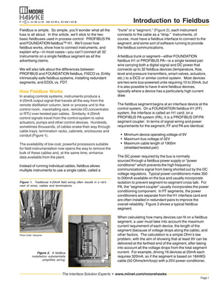
  • 7. Page7 The Interface Solution Experts • www.miinet.com/moorehawke Introduction to Fieldbus Most people are concerned with the amount of current each device draws from the fieldbus segment. However, the amount of voltage available at the field device is also a critical variable. For example, if devices on the segment draw too much current, and the segment has a long run, the increased current draw may result in too much voltage drop; consequently, some devices may get less than 9V. Although the devices get enough current, they do not get enough voltage. The MooreHawke ROUTEMASTER system can support two trunk cables for each segment. The two trunks run separately from the power conditioner to the field devices, but they are part of the same segment. Instead of one long segment, it uses two shorter trunks. Therefore, the total segment distance on each trunk leg is minimized, MooreHawke has a segment calculator (Figure 11), that helps calculate the number of devices per segment, based on the current and voltage requirements of each device, length of the segment, and other factors. It also bases its calculations on a requirement that each device receives at least 9V. device coupler (Figure 10). By splitting the intrinsically- safe current-limiting method in this unique way, the ROUTE-MASTER can put a full 350mA on the trunk that leads into hazardous areas with Gas Groups C&D, and still have intrinsically-safe spurs that match FF816 Group A&B approved devices. This overcomes both the FISCO and conventional Entity restrictions on available current. Instead, up to 16 devices can be put on a segment, nearly four times as many as a FISCO system, with a greatly reduced cost for hardware and labor. Figure 11. This segment calculator determines current and voltage requirements for a segment, and makes sure that all devices receive at least 9V of power. reducing the amount of voltage drop, and providing more than 9V to each device. FOUNDATION Fieldbus H1 vs. PROFIBUS PA From a field wiring perspective, FOUNDATION fieldbus and PROFIBUS are physically identical. They use the same twisted-pair cables and device couplers, and require the same segment terminators. Both handle up to 32 devices per segment. One primary difference is that PROFIBUS is a polling system, while FOUNDATION fieldbus utilizes cyclic transmission. Other differences include: • FF devices have scheduled times at which they transmit their information, whereas PA devices submit their data at random times. In PA, slave polling involves the bus master asking for information from the devices. The link active scheduler in FF has a timetable, so it determines when devices communicate on the segment. • Address allocation in PA has to be done by communication with each device individually, whereas FF devices will announce themselves to the bus master. • Each PA device will go back to the bus master with its info, which will then transmit to other devices the relevant data. FF devices can talk to each other and bypass the bus master, hence providing peer-to-peer communication. • FF devices can have built-in function blocks that allow them to talk to each other peer-to-peer, perform control functions, and continue to operate if communications are lost to the control system. PROFIBUS systems do not have function block capability. PROFIBUS instrumentation reports to and takes directions from the PA master; if communications to the PA Master(s) are lost, the instruments must go to a fail-safe position or maintain their last settings until directed otherwise. • FF and PA differ in the way that the segment control cards connect to the DCS or control system. FF uses an HSE (high speed Ethernet) network to connect remote H1 cards to the DCS; PA uses PROFIBUS DP, which is an RS-485 network, or PROFINET, an Ethernet-based network, to connect its PA devices to the DCS. DD, EDDL and FDT Both FF and PA systems require that instruments and controllers be “mapped” into the control system. That is, the DCS or control system must be told what devices are on the segment, what variables are to be input and output, and what functions are available. This is usually done with Device Description (DD) files, which are text-based
  • 8. Page8 The Interface Solution Experts • www.miinet.com/moorehawke Introduction to Fieldbus Specifications and information subject to change without notice.©2006 Moore Industries-International, Inc. • www.miinet.com United States • info@miinet.com Tel: (818) 894-7111 • FAX: (818) 891-2816 Australia • sales@mooreind.com.au Tel: (02) 8536-7200 • FAX: (02) 9525-7296 Belgium • info@mooreind.be Tel: 03/448.10.18 • FAX: 03/440.17.97 The Netherlands • sales@mooreind.nl Tel: (0)344-617971 • FAX: (0)344-615920 China • sales@mooreind.sh.cn Tel: 86-21-62491499 • FAX: 86-21-62490635 United Kingdom • sales@mooreind.com Tel: 01293 514488 • FAX: 01293 536852 files that can be downloaded from a web site into either an FF or PA-based control system. For example, DD files from all FF devices that have received FF certification can be downloaded from the Fieldbus Foundation web site. In general, DD files are universal; that is, they can be used in either a FF or PA system. During control system commissioning, DD files are downloaded into the control system’s equipment configuration. DD provides a standardized representation for the device that allows the host to interact with the device and allows the host to provide a consistent user interface for devices that is independent of the device type. EDDL (Electronic Device Description Language) and FDT/ DTM (Field Device Tool and Device Type Management) are more advanced ways to describe devices. Typically, EDDL is used by FF systems, while FDT/DTM is used by PA systems, but the two technologies are growing closer. EDDL starts with DD files. The DDL (Device Description Language) is the method for writing DD files. The next generation is EDDL (Electronic DDL), which provides additional information for GUI displays, configuration and calibration procedures, alarms and interfaces to higher- level software, such as MES, SCADA and plant historians. EDDL is independent of devices and operating systems. DTMs are vendor-specific drivers that interact with the device. DTMs allow more sophisticated programs to be written, so configuration and management tools such as PACTware can be used to configure and view vendor specific data. They are also dependent on the host operating system, while EDDL is not. To process the EDDL or FDT files, each control system vendor must have software capable of reading and understanding the files. For a while, a controversy existed in the fieldbus world, where some FF vendors would not accommodate FDT/DTM files, and vice versa. Fortunately, two of the biggest control system vendors recently agreed to patch up their differences and support both systems, so the EDDL vs. FDT controversy appears to be ending. Soon, most control system vendors will support both EDDL and FDT. An end user must ensure that all the instruments and field devices planned for a control system conform to the chosen fieldbus. If, for example, a FF system with EDDL is chosen, then all the instruments must have EDDL or DD files; conversely, a PB system with FDT/DTM must use instruments that have those files. Fortunately, it is relatively easy to check, simply by consulting the web sites for FF or PA. Justifying Fieldbus Fieldbus was initially justified by the considerable cost savings that resulted from using less wiring. Instead of running hundreds or thousands of wires, fieldbus often required only a few dozen segments or trunks. In recent years, the savings from running cables has been offset by the high cost of fieldbus components, and the reluctance of many users to install all the instruments possible on a segment. Being forced to provide for short circuits, for example, limits the number of instruments that can be put on a segment. In many cases, it’s a toss- up, from a hardware cost and labor perspective. In other cases, when the full capability of a segment can be used, hardware cost savings become more realistic. The true advantage of fieldbus is its ability to diagnose equipment problems, cut maintenance costs, provide information for asset management, allow control at the device level, and allow the use of smart devices. One oil company in Alaska did a study of savings it found by using a FOUNDATION fieldbus system. The savings included: • Wiring — They achieved a 98% reduction in home- run wiring because with fieldbus they could eliminate the costly maze of wiring between each remote field instrument and the control room. Terminations were also reduced by 84%. • Control room — Fewer terminations also freed up two-thirds of the cabinet space that would be required with traditional technology. • Commissioning — Field check-out and QA/AC time was reduced by 83%. Installation of each transmitter took only 20 minutes rather than the two hours needed with non-fieldbus technology. • Engineering drawings — Reduced the effort required for new drawings when adding oil wells by 92% because of FOUNDATION fieldbus and the host system’s configuration tools and object- oriented capabilities. The oil and gas industry was the first to fully embrace fieldbus, and now installs it at many new refineries, offshore platforms and other facilities. All product names are the property of their respective companies.