
Recommended
More Related Content
What's hot
What's hot (20)
Similar to Advanced computer network lab manual (practicals in Cisco Packet tracer)
Similar to Advanced computer network lab manual (practicals in Cisco Packet tracer) (20)
Recently uploaded
Recently uploaded (20)
Advanced computer network lab manual (practicals in Cisco Packet tracer)
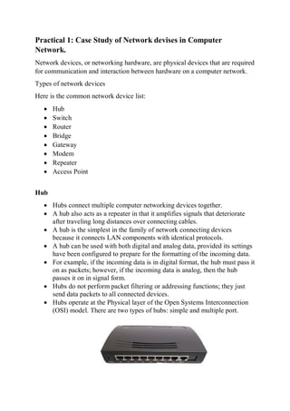
- 1. Practical 1: Case Study of Network devises in Computer Network. Network devices, or networking hardware, are physical devices that are required for communication and interaction between hardware on a computer network. Types of network devices Here is the common network device list: Hub Switch Router Bridge Gateway Modem Repeater Access Point Hub Hubs connect multiple computer networking devices together. A hub also acts as a repeater in that it amplifies signals that deteriorate after traveling long distances over connecting cables. A hub is the simplest in the family of network connecting devices because it connects LAN components with identical protocols. A hub can be used with both digital and analog data, provided its settings have been configured to prepare for the formatting of the incoming data. For example, if the incoming data is in digital format, the hub must pass it on as packets; however, if the incoming data is analog, then the hub passes it on in signal form. Hubs do not perform packet filtering or addressing functions; they just send data packets to all connected devices. Hubs operate at the Physical layer of the Open Systems Interconnection (OSI) model. There are two types of hubs: simple and multiple port.
- 2. Switch The switch maintains limited routing information about nodes in the internal network, and it allows connections to systems like hubs or routers. Strands of LANs are usually connected using switches. Generally, switches can read the hardware addresses of incoming packets to transmit them to the appropriate destination. Using switches improves network efficiency over hubs or routers because of the virtual circuit capability. Switches also improve network security because the virtual circuits are more difficult to examine with network monitors. You can think of a switch as a device that has some of the best capabilities of routers and hubs combined. A switch can work at either the Data Link layer or the Network layer of the OSI model. Router Routers help transmit packets to their destinations by charting a path through the sea of interconnected networking devices using different network topologies. Routers are intelligent devices, and they store information about the networks they’re connected to.
- 3. Most routers can be configured to operate as packet-filtering firewalls and use access control lists (ACLs). Routers, in conjunction with a channel service unit/data service unit (CSU/DSU), are also used to translate from LAN framing to WAN framing. This is needed because LANs and WANs use different network protocols. Such routers are known as border routers. They serve as the outside connection of a LAN to a WAN, and they operate at the border of your network. Bridge Bridges are used to connect two or more hosts or network segments together. The basic role of bridges in network architecture is storing and forwarding frames between the different segments that the bridge connects. They use hardware Media Access Control (MAC) addresses for transferring frames. By looking at the MAC address of the devices connected to each segment, bridges can forward the data or block it from crossing. Bridges can also be used to connect two physical LANs into a larger logical LAN. Bridges are like hubs in many respects, including the fact that they connect LAN components with identical protocols. However, bridges filter incoming data packets, known as frames, for addresses before they are forwarded. As it filters the data packets, the bridge makes no modifications to the format or content of the incoming data. The bridge filters and forwards frames on the network with the help of a dynamic bridge table.
- 4. Bridges have mostly fallen out of favor in recent years and have been replaced by switches, which offer more functionality. In fact, switches are sometimes referred to as “multiport bridges” because of how they operate. Gateway Gateways normally work at the Transport and Session layers of the OSI model. At the Transport layer and above, there are numerous protocols and standards from different vendors; gateways are used to deal with them. Gateways provide translation between networking technologies such as Open System Interconnection (OSI) and Transmission Control Protocol/Internet Protocol (TCP/IP). Because of this, gateways connect two or more autonomous networks, each with its own routing algorithms, protocols, topology, domain name service, and network administration procedures and policies. Gateways perform all of the functions of routers and more. In fact, a router with added translation functionality is a gateway. The function that does the translation between different network technologies is called a protocol converter.
- 5. Modem Modems (modulators-demodulators) are used to transmit digital signals over analog telephone lines. Thus, digital signals are converted by the modem into analog signals of different frequencies and transmitted to a modem at the receiving location. The receiving modem performs the reverse transformation and provides a digital output to a device connected to a modem, usually a computer. The digital data is usually transferred to or from the modem over a serial line through an industry standard interface, RS-232. Modems work on both the Physical and Data Link layers. Repeater A repeater is an electronic device that amplifies the signal it receives. You can think of repeater as a device which receives a signal and retransmits it at a higher level or higher power so that the signal can cover longer distances, more than 100 meters for standard LAN cables. Repeaters work on the Physical layer.
- 6. Access Point Access point (AP) can technically involve either a wired or wireless connection, it commonly means a wireless device. An AP works at the second OSI layer, the Data Link layer, and it can operate either as a bridge connecting a standard wired network to wireless devices or as a router passing data transmissions from one access point to another. Access points typically are separate network devices with a built-in antenna, transmitter and adapter. APs use the wireless infrastructure network mode to provide a connection point between WLANs and a wired Ethernet LAN. They also have several ports, giving you a way to expand the network to support additional clients. Depending on the size of the network, one or more APs might be required to provide full coverage.
- 7. Practical 2:Case Study of Cisco Packet tracer and types of topology. Cisco Packet Tracer Packet Tracer is a cross-platform visual simulation tool designed by Cisco Systems that allows users to create network topologies and imitate modern computer networks. The software allows users to simulate the configuration of Cisco routers and switches using a simulated command line interface. Packet Tracer makes use of a drag and drop user interface, allowing users to add and remove simulated network devices as they see fit. The software is mainly focused towards Certified Cisco Network Associate Academy students as an educational tool for helping them learn fundamental CCNA concepts. Previously students enrolled in a CCNA Academy program could freely download and use the tool free of charge for educational use. Students who spend more time in a hands-on mode of learning, with simulation and interactive capabilities, will be better equipped to apply concepts and configuration fundamentals when exposed to real equipment. As students gain practical experience with tasks such as configuration and troubleshooting, they become more confident in their abilities. Cisco Packet Tracer’s multiuser functionality also provides an opportunity for social learning, allowing students to collaborate and compete with each other and play games that enhance the learning experience. Key Features Packet Tracer : Cisco Packet Tracer has two workspaces— logical and physical. The logical workspace allows users to build logical network
- 8. topologies by placing, connecting, and clustering virtual network devices. The physical workspace provides a graphical physical dimension of the logical network, giving a sense of scale and placement in how network devices such as routers, switches, and hosts would look in a real environment. The physical view also provides geographic representations of networks, including multiple cities, buildings, and wiring closets. Packet Tracer Modes: Cisco Packet Tracer provides two operating modes to visualize the behavior of a network—real-time mode and simulation mode. In real-time mode the network behaves as real devices do, with immediate real-time response for all network activities. The real-time mode gives students a viable alternative to real equipment and allows them to gain configuration practice before working with real equipment. In simulation mode the user can see and control time intervals, the inner workings of data transfer, and the propagation of data across a network. This helps students understand the fundamental concepts behind network operations. A solid understanding of network fundamentals can help accelerate learning about related concepts.
- 9. Topologies The study of geometrical properties and spatial relations unaffected by the continuous change of shape or size of figures. 1.Mesh Topology : In mesh topology, every device is connected to another device via particular channel. Every device is connected with another via dedicated channels. These channels are known as links. If suppose, N number of devices are connected with each other in mesh topology, then total number of ports that is required by each device is ? N-1. In the Figure 1, there are 5 devices connected to each other, hence total number of ports required is 4. If suppose, N number of devices are connected with each other in mesh topology, then total number of dedicated links required to connect them is NC2 i.e. N(N-1)/2. In the Figure 1, there are 5 devices connected to each other, hence total number of links required is 5*4/2 = 10.
- 10. Advantages of this topology : It is robust. Fault is diagnosed easily. Data is reliable because data is transferred among the devices through dedicated channels or links. Provides security and privacy. Problems with this topology : Installation and configuration is difficult. Cost of cables are high as bulk wiring is required, hence suitable for less number of devices. Cost of maintenance is high. 2.Star Topology : In star topology, all the devices are connected to a single hub through a cable. This hub is the central node and all others nodes are connected to the central node. The hub can be passive in nature i.e. not intelligent hub such as broadcasting devices, at the same time the hub can be intelligent known as active hubs. Active hubs have repeaters in them. A star topology having four systems connected to single point of connection i.e. hub.
- 11. Advantages of this topology : If N devices are connected to each other in star topology, then the number of cables required to connect them is N. So, it is easy to set up. Each device require only 1 port i.e. to connect to the hub. Problems with this topology : If the concentrator (hub) on which the whole topology relies fails, the whole system will crash down. Cost of installation is high. Performance is based on the single concentrator i.e. hub. 3.Bus Topology : Bus topology is a network type in which every computer and network device is connected to single cable. It transmits the data from one end to another in single direction. No bi-directional feature is in bus topology. A bus topology with shared backbone cable. The nodes are connected to the channel via drop lines. Advantages of this topology : If N devices are connected to each other in bus topology, then the number of cables required to connect them is 1 which is known as backbone cable and N drop lines are required. Cost of the cable is less as compared to other topology, but it is used to built small networks.
- 12. Problems with this topology : If the common cable fails, then the whole system will crash down. If the network traffic is heavy, it increases collisions in the network. To avoid this, various protocols are used in MAC layer known as Pure Aloha, Slotted Aloha, CSMA/CD etc. 4.Ring Topology : In this topology, it forms a ring connecting devices with its exactly two neighboring devices. A number of repeaters are used for Ring topology with a large number of nodes, because if someone wants to send some data to the last node in the ring topology with 100 nodes, then the data will have to pass through 99 nodes to reach the 100th node. Hence to prevent data loss repeaters are used in the network. The transmission is unidirectional, but it can be made bidirectional by having 2 connections between each Network Node, it is called Dual Ring Topology. A ring topology comprises of 4 stations connected with each forming a ring.. The following operations takes place in ring topology are : 1. One station is known as monitor station which takes all the responsibility to perform the operations. 2. To transmit the data, station has to hold the token. After the transmission is done, the token is to be released for other stations to use.
- 13. 3. When no station is transmitting the data, then the token will circulate in the ring. 4. There are two types of token release techniques : Early token release releases the token just after the transmitting the data and Delay token release releases the token after the acknowledgement is received from the receiver. Advantages of this topology : The possibility of collision is minimum in this type of topology. Cheap to install and expand. Problems with this topology : Troubleshooting is difficult in this topology. Addition of stations in between or removal of stations can disturb the whole topology. 5.Tree Topology : This topology is the variation of Star topology. This topology have hierarchical flow of data. In this the various secondary hubs are connected to the central hub which contains the repeater. In this data flow from top to bottom i.e from the central hub to secondary and then to the devices or from bottom to top i.e. devices to secondary hub and then to the central hub. Advantages of this topology :
- 14. It allows more devices to be attached to a single central hub thus it increases the distance that is travel by the signal to come to the devices. It allows the network to get isolate and also prioritize from different computers. Problems with this topology : If the central hub gets fails the entire system fails. The cost is high because of cabling.
- 15. Practical 3:Configure and implement the types of Network Topology in Cisco Packet Tracer. Topology Steps of making Topology Bus Topology 1.Take all required devices in cisco packet tracer. 3 PC 3 Switches 2.Using cable connect all devices Connect three switches to each other as shown in fig Connect every PC to according to switch. 3.Give IP address. In Desktop->In static->IPv4 Give sequence vise ip address to pc 192.168.0.1 for pc3 Follow same steps for another two pcs Give ip as 192.168.0.2 pc0 Give ip as 192.168.0.3 pc2 4.wait until arrow become green
- 17. Mesh Topology 1.Take all required devices in cisco packet tracer. 4 PC 4 Switches 2.Using cable connect all devices Connect four switches to each other as shown in fig Make sure that no one switch is available that does not connect with each other. Connect every PC to according to switch. 3.Give IP address. In Desktop->In static->IPv4 and default gateway Please make note default gateway is same for every pc 192.168.2.1 Give sequence vise ip address to pc 192.168.0.1 for pc0 Follow same steps for another two pcs Give ip as 192.168.0.2 pc1 Give ip as 192.168.0.4 pc2 Give ip as 192.168.0.3 pc3 4.wait until arrow become green
- 19. Ring Topology 1.Take all required devices in cisco packet tracer. 4 PC 4 Switches 2.Using cable connect all devices Connect four switches to each other as shown in fig Connect every PC to according to switch. 3.Give IP address. In Desktop->In static->IPv4 Give sequence vise ip address to pc 192.168.0.1 for pc0 Follow same steps for another two pcs Give ip as 192.168.0.2 pc1 Give ip as 192.168.0.4 pc3 Give ip as 192.168.0.5 pc4 4.wait until arrow become green
- 21. Star Topology 1.Take all required devices in cisco packet tracer. 4 PC 1 Switches 2.Using cable connect all devices Connect four pc to one switch as shown in fig Connect every PC to according to switch. 3.Give IP address. In Desktop->In static->IPv4 Give sequence vise ip address to pc 192.168.0.1 for pc0 Follow same steps for another two pcs Give ip as 192.168.0.2 pc1 Give ip as 192.168.0.3 pc2 Give ip as 192.168.0.4 pc3 4.wait until arrow become green
- 23. Practical 4: To Build the simple Network with using Logical Topology like Mesh, Bus, Ring, Star etc. Steps of making all topology connected 1.Take all required devices in cisco packet tracer. 15 PC 3 Router 12 Switches 2.Using cable connect all devices Connect three PC to one switch same for another Connect two routers with each other 4.Give IP address and default gateway to PC In desktop IP config give IP address in static In Desktop->In static->IPv4 Also set value of default gateway (different for every topology but same for each PC which connected in same topology) Labeling both the values 5. Enable the port of router according to connection 6.Take packet and transfer from one pc to another pc make attention that both the pc are belong to different topology 7.observe the result in simulation.
- 24. (a)All topology connected Bus Topology (b)Bus topology
- 25. Ring Topology (c)Ring topology Star Topology (d)Star topology
- 27. Packet transferring (f)Packet are transfer from one pc to another we can see all the protocols in simulator
- 28. (g)Stp protocol and we can see success in simulation that packet is transferring successfully (h)In this packet transferring is in progress
- 29. Practical 5: To creating a LAN Segment using Cisco Packet Tracer. Steps of making LAN Segment 1.Take all required devices in cisco packet tracer. 3 PC 2 Laptop 1 Switches 2.Using cable connect all devices Connect three PC to one switch same for another Connect two Laptop to one switch 4.Give IP address and default gateway to PC In desktop IP config give IP address in static In Desktop->In static->IPv4 Also set value of default gateway (different for every topology but same for each PC which connected in same topology) 5. Enable the port of Switch according to connection 6.Give command in CLI of PC Ping IP address
- 30. (a)Lansegment
- 31. (b)give static IP to PC
- 32. (b)give static IP to laptop
- 33. (c)give static IP to PC1
- 34. (c)give static IP to PC0
- 35. (d)give static IP to laptop
- 36. (e)write ping command in CLI of laptop
- 37. (f)write ping command in CLI of PC1
- 38. (g)write ping command in CLI of PC2
- 39. Practical 6: To configure Subnet planning and its implementation. Steps of making Subnet Planning 1.Take all required devices in cisco packet tracer. 8 PC 2 Router 4 Switches 2.Using cable connect all devices Connect three PC to one switch same for another Connect two router with each other and two switches to router. 4.Give IP address and default gateway to PC In desktop IP config give IP address in static In Desktop->In static->IPv4 Also set value of default gateway (same for every two pcs which are connected with one switch is as same) Give subnet mask according from router to switch. 5. Enable the port of Switch according to connection Connect serial to serial connection between router give appropriate ip address as shown in fig.
- 40. (a)Subnetting
- 41. (b)Give address to serial port 2/0
- 42. (c)Give address to FastEthernet port 1/0
- 43. (d)Give address to FastEthernet port 0/0
- 44. (e)Give address to FastEthernet port 1/0
- 45. (f)give static IP to PC7
- 46. (g)give static IP to PC6
- 47. (h)give static IP to PC5
- 48. (i)give static IP to PC4
- 49. (j)give static IP to PC3
- 50. (k)give static IP to PC2
- 51. (l)give static IP to PC1
- 52. (m)give static IP to PC0
- 53. (n)give address to serial port 2/0
- 54. Practical 7:Configure the types of Commands and configure DHCP, HTTP and DNS Server with using Cisco Packet Tracer. Steps of making Http with DHCP and DNS with Web server 1.Take all required devices in cisco packet tracer. 6 PC 2 Router 2 Switches 4 Server 2.Make the name of each Server DHCP DNS DHCP2 www.server 3.Using cable connect all devices Connect three PC to one switch same for another Connect two router with each other Connect one server with one switch and another three server to other one switch 4.Make server according to name To Make first DHCP server 1. Give Ipv4 address as static 2. Set Default and subnet mask 3. In services Set DHCP server pool To make DNS server 1. Give Ipv4 address as static 2. Set Default and subnet mask 3. In services give name of DNS domain as www.server and give IP address To make HTTP server 1. Give Ipv4 address as static 2. Set Default and subnet mask 3. In services make on HTTP service 5.Request for IP to all PC as DHCP in IP address 6.Eanble the port of router according to connection
- 55. (a)All the devices are connected using router also DHCP,DNS and Server in one figure (b) Request DHCP for IP address in PC4
- 56. (c)Request DHCP for IP address in PC3
- 57. (d)Request DHCP for IP address in PC2
- 58. (e)Request DHCP for IP address in PC1
- 59. (f)Request DHCP for IP address in PC0
- 60. (g)Give Static IP address in DHCP2
- 61. (h) Request DHCP for IP address in PC3
- 62. (i) Give Static IP address in www.server
- 63. (j) Give Static IP address in DHCP2
- 64. (k)on the HTTP services in DNS
- 65. (l) on the services of DNS and add server as www.server
- 66. (m) on the HTTP services in DNS
- 67. (n)on the services of DHCP server and add server pool and IP address
- 68. Practical 8: To configure e - mail using Http, DNS and DHCP server using Cisco Packet Tracer. Http server Steps of making Http with Web server 1.Take all required devices in cisco packet tracer. 4 PC 3 Server 2.Make the name of each Server Server0 Server1 httpserver 3.Using cable connect all devices Connect four PC to one switch Connect three server to one switch 4.Make server according to name To Make Server0 as DHCP server 1. Give Ipv4 address as static 2. Set Default and subnet mask 3. In services Set DHCP server pool To make Server1 as DNS server 1. Give Ipv4 address as static 2. Set Default and subnet mask 3. In services give name of DNS domain as www.server and give IP address To make httpserver as HTTP server 1. Give Ipv4 address as static 2. Set Default and subnet mask 3. In services make on HTTP service 5.Request for IP to all PC as DHCP in IP address 6.We can see the web page which are run on PCs as in desktop->web browser- >url type “httpserver”
- 69. (a)all devices are connected using one switch in http
- 70. (b)set IP as static and give IP address in server1
- 71. (c)set IP as static and give IP address in server0
- 72. (d)set IP as static and give IP address in httpserver
- 73. (e)set IP as static and give IP address in PC3
- 74. (f)set IP as static and give IP address in PC2
- 75. (g)Request DHCP for IP address in PC1
- 76. (h)Request DHCP for IP address in PC0
- 77. (i)on the service of DNS in Server1
- 78. (j)on the service of DHCP in Server0
- 79. (k)on the service of http in httpserver
- 80. (l)In the web browser of URL httpserver
- 81. (m)Same as above figure
- 82. Email.com Steps of making Email Web server 1.Take all required devices in cisco packet tracer. 3 PC 3 Server 2.Make the name of each Server Server0 Server1 httpserver 3.Using cable connect all devices Connect three PC to one switch Connect three server to one switch 4.Make server according to name To Make DHCP server 1.Give Ipv4 address as static 2.Set Default and subnet mask 3.In services Set DHCP server pool To make DNS server 1.Give Ipv4 address as static 2.Set Default and subnet mask 3.In services give name of DNS domain email.com and give IP address To make Server as Email 1.Give Ipv4 address as static 2.Set Default and subnet mask 3.In services make on HTTP service 4.In Email.com server email ->give domain name and give username and password 5.Request for IP to all PC as DHCP in IP address 6.send email from one pc to another pc to check whether it works or not In pc->desktop->email->set name and password Same for another pc Compose email and send to it
- 83. (a)all devices are connected using one switch
- 84. (b)Request DHCP for IP address in PC4
- 85. (c)Request DHCP for IP address in PC3
- 86. (d)Request DHCP for IP address in PC5
- 87. (e)Request DHCP for IP address in PC4
- 88. (f)Request DHCP for IP address in PC3
- 89. (g)set IP address in DNS as static
- 90. (h)Request DHCP for IP address in PC1
- 91. (i)on the services in DHCP for IP address in dhcp
- 92. (j)on the service of Email in Email.com
- 93. (k)compose the mail and type the message in pc3
- 94. (l)compose the mail and type the message in pc5
- 95. Practical 9: Implement the Program for Distance Vector Routing (Routing Information Protocol – RIP using Cisco Packet Tracer) Steps of making RIP(Routing Information Protocol) 1.Take all required devices in cisco packet tracer. 3 PC 3 Router 3 Switches 2.Using cable connect all devices Connect three PC to three switch according to diagram. Connect three router with each other as shown in fig and Connect router to switch as shown in fig 3.Give IP address using Desktop->Ip->static 4.In router write command in CLI 5.Eanble the port of router according to connection (a)Three Routers are connected with three switch and switch connected with pc
- 96. (b)Give the address to serial port 3/0
- 97. (c)Give the address to serial port 2/0
- 98. (d)Give the address to Fast Ethernet 0/0 in router 5
- 99. (e)Give command to router for setting up the serial link router 4
- 100. (f)Give command to router 3 for setting up the serial and fastethernet link
- 101. (g)Give the address to serial port 3/0 router 4
- 102. (h)Give the address to serial port 2/0 in router 4
- 103. (i)Give the address to Fast Ethernet 3/0 in router 4
- 104. (j)Give the address to serial port 3/0 in router 4
- 105. (k)Give the address to serial port 2/0 in router 3
- 106. (l)Give the address to serial port 3/0 in router 3
- 107. (m)Give Static IP address to PC2
- 109. (n)Give Static IP address to PC0
- 110. (n) Give command to router 5 for setting up the serial and fastethernet link
- 111. Practical 10: To configure the Address Resolution Protocol – ARP and File Transfer Protocol – FTP. Steps of making ARP(Address Resolution Protocol) 1.Take all required devices in cisco packet tracer. 3 PC 1 Switches 2.Using cable connect all devices Connect three PC to one switch according to diagram. 3.Give IP address using Desktop->Ip->static. 4.Take packet and transfer from any one pc to another see in figure. See in Simulation ARP protocol 5.Eanble the port of router according to connection 6.Using ping command and arp command in CLI we see the output (a) Devices are connected in star topology for ARP evaluation
- 112. (b)Give IP address to PC1
- 113. (c)Give IP address to PC0
- 114. (d)Give IP address to PC2
- 115. (e)Write Ping Command in CLI of PC2
- 116. (f)Observe the result in simulation panel
- 117. (g)Write Ping Command in CLI of PC2
- 118. Steps of making FTP(File Transfer Protocol) 1.Take all required devices in cisco packet tracer. 3 PC 1 Router 2 Switches 1 Server 2.Using cable connect all devices Connect two PC to one switch according to diagram. Connect one router to another switch Connect server and pc to switch as shown in fig 3.Give IP address to Pc and server using Desktop->Ip->static 4.In server Ftp service add Username and Password and add text file. For adding text file in pc make text file and save it using name. 5.In router give serial address according to port and same for ethernet 6.In router write command in CLI ftp server address dir put filename after uploading file on server we can access the file from any other pc 7.Eanble the port of router according to connection 8.We can access the file from any other pc using ftp command
- 119. (a)devices are connected for transferring file (FTP)
- 120. (b)Give Static IP address to PC4
- 122. (c)Give Static IP address to PC5
- 123. (d)Add Username and password in Server0
- 124. (e)Give Static IP address to Server0
- 125. (f)Give ftp command to PC5
- 126. (g)Give ftp command to PC5
- 127. (h)Give ftp command to PC5
- 128. (i)Give ftp command to PC5
- 129. (j)dir command in CLI of pc5
- 130. Practical 11: To configure the BGP protocol in Cisco Packet Trace. Steps of making BGP (Border Gateway Protocol) 1.Take all required devices in cisco packet tracer. 4 PC 3 Router 2 Switches 2.Using cable connect all devices Connect two PC to one switch according to diagram. Connect three routers with each other as shown in fig and Connect router to switch as shown in fig 3.Give IP address using Desktop->Ip->static 4.In router give serial address according to port and same for ethernet 5.In router write command in CLI 6.Eanble the port of router according to connection
- 131. (a)connected router and switch as shown above (b)connected router and switch as shown above for part 2
- 132. (c)Give static IP address to PC7
- 133. (d)Give static IP address to PC4
- 134. (e)Give static IP address to PC6
- 135. (f)Give command in router 1 for setting up the link
- 136. (g)Give the address to serial 2/0 to router 1
- 137. (h) Give command in router 1 for setting up the link
- 138. (i)Give the address to serial 3/0 to router 7
- 139. (j)Give the address to serial 2/0 to router 7
- 140. (k)Give command in router 0 for setting up the link
- 141. (l)Give static IP address to PC5
- 142. Practical 12: To Configure Open Shortest Path First – OSPF in packet trace. Steps of making OSPF (Open Shortest Path First) 1.Take all required devices in cisco packet tracer. 3 PC 3 Router 3 Switches 2.Using cable connect all devices Connect three PC to three switch according to diagram. Connect three routers with each other as shown in fig and Connect router to switch as shown in fig 3.Give IP address using Desktop->Ip->static 4.In router give serial address according to port and ethernet address according to port. 4.In router write command in CLI 5.Eanble the port of router according to connection 6.We can see OSPF protocol in simulator
- 143. (a)set all the router in triangle and give Ip to PCS
- 144. (b)Give static IP to PC1
- 145. (c)Give static IP to PC0
- 146. (d)Give static IP to PC2
- 147. (e)write command in CLI of router for setting up the link
- 148. (d)observe the result in simulation as OSPF protocol is present
- 149. Practical 13: To configure single area and multipath area in OSPF using Cisco Packet Tracer. Steps of Making MOSPF and OSPF 1. Take four PT-Router, two 2950-24 switch ,four PC. 2. Connect router with switch using copper straight through wire using fast ethernet and connect both pc to switches using same cable. Connect three router with single path as shown in diagram using serial DTE. 1.Connect serial 2/0 to serial 2/0 for Router 1 to Router 0 2. Connect serial 3/0 to serial 3/0 for Router 0 to Router 2 3. Connect serial 2/0 to serial 2/0 for Router 2 to Router 3 3. Labelling to all devices and between the devices for our reference. Make label as shown in fig. 4. Give IP address to all PCS as static. PC0-192.168.1.2 PC1-192.168.1.3 PC2-192.168.2.2 PC3-192.168.2.3 5. To configure MOSPF first make connection between all the devices using CLI of every devices.as shown in fig all the devices give command. first enable the router and then connect router with corresponding router and connect pc to corresponding router.
- 150. (a)Here we see the success status of packet transfering in MOSPF (b)three routers are connected with four PCS for MOSPF
- 151. (c)Give IP address to PC2
- 152. (d)Give IP address to PC1
- 153. (e)Give IP address to PC0
- 154. (f)Give IP address to PC3
- 155. (g)add ip address and set up the link in router 1
- 156. (h)Add network area in router 0
- 157. (i) add ip address and set up the link in router 0
- 158. (j) add ip address and set up the link in router 2
- 159. (k) add ip address and set up the link in router 3
- 160. (l)Add network address in Router 1
- 161. (m)Add network address in Router 0
- 162. (n)add network address in router 2
- 163. (o)add network address in router 3
- 164. (p)show the ip route in Router 1
- 165. (q)Check the ping Command in PC0
- 166. (r)observing the simulation OSPF (S)Successfully packet transfer (s)Give IP address to PC2
- 167. Practical 14: To configure Voice over IP – VOIP in cisco packet trace. Steps of making VOIP 1. Take one 2811 Router, one 2950-24 switch ,two 7960 ip phone. 2. Connect router with switch using copper straight through wire and connect both phones to switches using same cable. 3. Labelling to all devices for our reference. Router-10.0.0.1 Phone1-0001 Phone2-0002 4. To configure go to the CLI of Router and type command as shown in below figure ,follow same for configure the switch. 5. We can connect both phone using VOIP and also see in fig as connected.
- 168. (a)Two telephones are connected with one router
- 169. (b)Add address and network in router 1
- 170. (c)add telephone number in Router 1
- 171. (d)add telephone number in Router 1
- 172. (e)change the physical device in IP phone1
- 173. (f)Enable the port for VIOP
- 174. (g)after dailing the IP Phone0 is connected with each other
- 175. (h)after dailing the IP Phone1 is connected with each other
- 176. Practical 15: Implementation of Wireless Network with using Cisco Packet tracer. Steps of making Wireless Network 1.Take all required devices in cisco packet tracer. 4 PC 1 Laptop 1 Router-1841 1 Switch 1 wireless Router 2.Using cable connect all devices Connect three PC to one switch according to diagram. Connect one router with one switch each other as shown in fig and Connect router to switch as shown in fig Connect wireless router to router and wireless router to switch For connection between wireless router to pc and laptop go to wireless router->config->wireless->wep->1234567890 Set wireless connection in pc and desktop using following command 3.Give IP address using Desktop->Ip->static 4.In router give serial address according to port and ethernet address according to port. 4.switch of the cpu of pc and remove existing device add Wmp300n in the pc and switch on it. for connecting wireless network follow the below steps. Desktop->pc->wireless->connect->wep key provide 5.Eanble the port of router according to connection 6.We can see wireless network in figure.
- 177. (a)using wireless network devices are connected with each other (b)successfully transfer the packet using wireless network
- 178. (c)after adding wireless connection connect laptop to it
- 179. (d)after adding wireless connection connect laptop to it
- 180. (e)set up the serial and fast ethernet link of router 0
- 181. (f)set up the serial and fast ethernet link of router 0
- 182. (g)Give Ip address to fast ethernet 0/1 of router 0
- 183. (h)Give Ip address to fast ethernet 0/0 of router 0
- 184. (i)Add WEP in Wireless routing for access network (j)successfully transfer the packet from PC0 to Laptop0
- 185. (k)Observe simulation panel and see different protocol
- 186. Practical 16: To study of Network Simulator and Simulation of congestion Control Algorithm using Network Simulator. Network simulation is a technique whereby a software program models the behaviour of a network by calculating the interaction between the different network entities (routers, switches, nodes, access points, links etc.). Most simulators use discrete event simulation - the modelling of systems in which state variables change at discrete points in time. The behaviour of the network and the various applications and services it supports can then be observed in a test lab various attributes of the environment can also be modified in a controlled manner to assess how the network / protocols would behave under different conditions. A network simulator is software that predicts the behaviour of a computer network. Since communication networks have become too complex for traditional analytical methods to provide an accurate understanding of system behaviour, network simulators are used. In simulators, the computer network is modelled with devices, links, applications etc. and the network performance is reported. Simulators come with support for the most popular technologies and networks in use today such as 5G, Internet of Things (IoT), Wireless LANs, mobile ad hoc networks, wireless sensor networks, vehicular ad hoc networks, cognitive radio networks, LTE etc Algorithm Recent advances in wireless sensor networks (WSNs) have lead to applications with increased traffic demands. Research is evolving from applications where performance is not considered as a crucial factor, to applications where performance is a critical factor. There are many cases in the fields of automation, health monitoring, and disaster response that demand wireless sensor networks where performance assurances are vital, especially for parameters like power, delay, and reliability.
- 187. Due to the nature of these networks the higher amount of traffic is observed when the monitored event takes place. Exactly at this instance, there is a higher probability of congestion appearance in the network. Congestion in WSNs is tackled by the employment of two methods: either by reducing the load (“traffic control”), or by increasing the resources (“resource control”). In this paper we present the Hierarchical Tree Alternative Path (HTAP) algorithm, a “resource control” algorithm that attempts, through simple steps and minor computations, to mitigate congestion in wireless sensor networks by creating dynamic alternative paths to the sink. HTAP is evaluated in several scenarios in comparison with another “resource control” algorithm (TARA), as well as with a “traffic control” algorithm (SenTCP), and also the case where no congestion control exists in the network (“no CC”). Results show that HTAP is a simple and efficient algorithm capable of dealing successfully with congestion in WSNs, while preserving the performance characteristics of the network.
- 188. Practical 17:To configure the Network address translation (NAT) in statically and dynamically using cisco packet tracer. Steps of making NAT(Network Address Transmission -static) 1.Take all required devices in cisco packet tracer. 2 PC 2 2960-24T Switches 2 Servers 2 1841 Routers 2.Using cable connect all devices Connect one PC and one server to one switch according to diagram. Same for another one Pc and server Labeling the PC and other devices according to diagram 3.Give IP address Give IP address to PC and Server using Desktop->Ip->static Give IP to Serial and fast Ethernet according to router 4.Make server according to name Make both server as DNS and on the services of HTTP Give name and address in DNS services 5.Eanble the port of router according to connection
- 189. (a)Connected all devices to Servers ,PC and Routers
- 190. (b)on the services of DNS in costomerserver.com
- 191. (c)Give Static IP to Customerserver.com
- 192. (d)Give Static IP to Customer PC
- 193. (e)on the services of HTTP in costomerserver.com
- 194. (f)Give address to fast ethernet port 0/1 in ISP router
- 195. (g)Give address to fast ethernet port 0/0 in ISP router
- 196. (h)Give address to fast ethernet port 0/1 in Customer router
- 197. (i)Give address to fast ethernet port 0/0 in Customer router
- 198. (j)Give static IP address to ISP workstation
- 199. (k)on the services of HTTP in ispserver.com
- 200. (l)on the services of DNS in ispserver.com
- 201. Steps of making NAT(Network Address Transmission -Dynamic) 1.Take all required devices in cisco packet tracer. 2 PC 2 Switches 1 Servers 2 Routers 2.Using cable connect all devices Connect two PC and one router through one switch according to diagram. Connect two routers with each other 3.Give IP address Give IP address to PC and Server using Desktop->Ip->static Give IP to Serial and fast Ethernet according to router 4.Make server according to name on the services of HTTP 5.Eanble the port of router according to connection
- 202. (a)Devices are connected in Dynamic NAT
- 203. (b)interface command in CLI of Router 4
- 204. (c)Give IP address to Fast Ethernet 0/1 in router 4
- 205. (d) Give IP address to Fast Ethernet 0/0 in router 4
- 206. (e) interface command in CLI of Router 4
- 207. (f) Give IP address to Fast Ethernet 0/1 in router 3
- 208. (g) Give IP address to Fast Ethernet 0/0 in router 3
- 209. (h) Give static IP address to server2
- 210. (i)On the services of Http in Server2
- 211. (j) Give static IP address to PC3
- 212. (k) Give static IP address to PC2
- 213. (l) interface command in CLI of Router 3
- 214. Practical 18: Configure default router and static route in cisco packet tracer Steps of making default router and static route in cisco packet tracer 1.Take all required devices in cisco packet tracer. 6 PC 2 Router 2 Switches 2.Using cable connect all devices Connect three PC to one switch same for another Connect two router with each other 4.Give IP address and default gateway to PC In desktop IP config give IP address in static In Desktop->In static->IPv4 Also set value of default gateway (different for every topology but same for each PC which connected in same topology) Write interface command and IP address for each router as shown in fig 5. Enable the port of Switch according to connection 6.Give command in CLI of PC Ping
- 215. (a)devices are connected through two router and two star topology present here
- 216. (b)we see simulation panel that shows different type of protocols
- 217. (c)Give static IP address to PC4
- 218. (d)Give static IP address to PC3
- 219. (e)Give static IP address to PC2
- 220. (f)Give static IP address to PC1
- 221. (g)Give static IP address to PC0
- 222. (h)Give static IP address to PC2
- 223. (i)Give command to CLI about IP address of Router1
- 224. (j)Give command to CLI about IP address of Router1
- 225. (k)Give command to CLI about IP address of Router4
- 226. (l)Give command to CLI about IP address of Router1
- 227. (m)Give ping command to CLI to PC1
- 228. Practical 19: Creating TCP/IP connection in Network Simulator – NS2 tool. TCP/IP means of communication ideal of TCP methods to the replies and amends of the data communication rate. We build innovative research via submit to process new technological innovation. In which it is made as a result of research also for scholar’s carriers to be relaxed. Implementing four layers of TCP IP in NS2 using a standard algorithm reno for routing applications. What is TCP/IP TCP defines how to establish and also maintain a network conversation, and TCP works with IP. IP defines how to send data also to each other. TCP/IP is a basic communication language on the internet. Tcp/Ip uses the client/server model, also for communication. TCP/Ip has a two-layer program which includes, Higher layer And also in the Lower layer Simulation Simulation is the process of learning by doing. Whenever there is something new in the world, we try to analyse it first by examining it and in the process get to learn a lot of things. This entire course is called as Simulation. Correlating to this process, in order to understand all the complexities one need to model the entire role-play in form of computer simulation, the need is to build artificial objects and assign them roles dynamically. Computer simulation is the designing of a theoretical physical system on a digital computer with emphasis on model designing, execution and analysis. After creation of the mathematical model the most important step is to create a computer program for updating the state and event variables through time (by time slicing or event scheduling). If this simulation is carried out successively in parallel computers, it is called Parallel or Distributed simulation.
- 229. Network simulation (NS) is one of the types of simulation, which is used to simulate the networks such as in MANETs, VANETs etc. It provides simulation for routing and multicast protocols for both wired and wireless networks. NS is licensed for use under version 2 of the GNU (General Public License) and is popularly known as NS2. It is an object-oriented, discrete event-driven simulator written in C++ and Otcl/tcl.NS-2 can be used to implement network protocols such as TCP and UPD, traffic source behavior such as FTP, Telnet, Web, CBR and VBR, router queue management mechanism such as Drop Tail, RED and CBQ, routing algorithms and many more. In ns2, C++ is used for detailed protocol implementation and Otcl is used for the setup. The compiled C++ objects are made available to the Otcl interpreter and in this way, the ready-made C++ objects can be controlled from the OTcl level. Install NS-2 using this command : sudo apt-get install ns2 Nam is also needed to install. Nam (Network Animator) is an animation tool to graphically represent the network and packet traces. Use this command : sudo apt-get install nam set a 8 set b [expr $a/8] In the first line, the variable a is assigned the value 8. In the second line, the result of the command [expr $a/8], which equals 1, is then used as an argument to another command, which in turn assigns a value to the variable b. The “$” sign is used to obtain a value contained in a variable and square brackets are an indication of a command substitution.