Wireless networks & cellular wireless networks
•
0 likes•222 views

WIRELESS NETWORKS & CELLULAR WIRELESS NETWORKS Wireless network, Wireless network Architecture Classification of wireless networks – WBAN, WPAN, WLAN, WMAN, WWAN. IEEE 802.11, IEEE 802.16, Bluetooth – Standards, Architecture and Services Principles of cellular networks – cellular network organization Operation of cellular systems, Generation of cellular networks – 1G, 2G, 2.5G, 3G and 4G.

Recommended
More Related Content
What's hot
What's hot (20)
Similar to Wireless networks & cellular wireless networks
Similar to Wireless networks & cellular wireless networks (20)
More from Sweta Kumari Barnwal
More from Sweta Kumari Barnwal (20)
Recently uploaded
Recently uploaded (20)
Wireless networks & cellular wireless networks
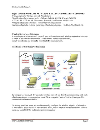
- 1. Wireless Mobile Network SWETA KUMARI BARNWAL Page 1 Topics Covered: WIRELESS NETWORKS & CELLULAR WIRELESS NETWORKS Wireless network, Wireless network Architecture Classification of wireless networks – WBAN, WPAN, WLAN, WMAN, WWAN. IEEE 802.11, IEEE 802.16, Bluetooth – Standards, Architecture and Services Principles of cellular networks – cellular network organization Operation of cellular systems, Generation of cellular networks – 1G, 2G, 2.5G, 3G and 4G. Wireless Network Architectures In planning the wireless network, we will have to determine which wireless network architecture to adopt in the network environment. There are two architectures available, namely standalone and centrally coordinated wireless network. Standalone architecture (Ad hoc mode) By using ad hoc mode, all devices in the wireless network are directly communicating with each other in peer to peer communication mode. No access point (routers/switches) is required for communication between devices. For setting up ad hoc mode, we need to manually configure the wireless adaptors of all devices to be at ad hoc mode instead of infrastructure mode, and all adaptors must use the same channel name and same SSID for making the connection active.
- 2. Wireless Mobile Network SWETA KUMARI BARNWAL Page 2 Ad hoc mode is most suitable for small group of devices and all of these devices must be physically present in close proximity with each other. The performance of network suffers while the number of devices grows. Disconnections of random device may occur frequently and also, ad hoc mode can be a tough job for network administrator to manage the network. Ad hoc mode has another limitation is that, ad hoc mode networks cannot bridge to wired local area network and also cannot access internet if without the installation of special gateways. However, Ad hoc mode works fine in small environment. Because ad hoc mode does not need any extra access point (routers/switches), therefore it reduces the cost. Ad hoc can be very useful as a backup option for time being if network based on centrally coordinated wireless network (infrastructure mode) and access points are malfunctioning. An ad hoc mode uses the integrated functionality of each adaptor to enable wireless services and security authentication. The characteristics of an Ad hoc wireless network are listed as below: • All access points in the network operate independently and has own configuration file. • Access point is responsible for the encryption and decryption. • The network configuration is static and does not respond to changing network conditions. Centrally Coordinated Architecture (Infrastructure mode) The other architecture in wireless network is centrally coordinated (infrastructure mode). All devices are connected to wireless network with the help of Access Point (AP). Wireless APs are usually routers or switches which are connected to internet by broadband modem.
- 3. Wireless Mobile Network SWETA KUMARI BARNWAL Page 3 Infrastructure mode deployments are more suitable for larger organizations or facility. This kind of deployment helps to simplify network management, and allows the facility to address operational concerns. And resiliency is also assured while more users can get connected to the network subsequently. The infrastructure mode provides improved security, ease of management, and much more scalability and stability. However, the infrastructure mode incurs extra cost in deploying access points such as routers or switches. An infrastructure mode wireless network has the characteristics as below: • The wireless centralized controller coordinates the activity of access point. • The controller is able to monitor and control the wireless network by automatically reconfiguring the access point parameters in order to maintain the health of the network. • The wireless network can be easily expanded or reduced by adding or removing access points and the network can be reconfigured by the controller based on the changes in RF footprint. • Tasks such as user authentication, fault tolerance, control of configuration, policy enforcement and expansion of network are done by the wireless network controller. • Redundant access points can be deployed in separate locations to maintain control in the event of an access point or switch failure. Types of Wireless networking technology and Comparison The wireless networking use radio waves and/or microwaves to maintain communications in among devices of sender and receiver such as laptops to the Internet, the business network and applications. Hence a wireless networking is a computer networking technology that enables user devices to communicate and access applications and information without connected by wires of any kinds. When any wireless network device connected to Wi-Fi hot spots in public place, the connection is established to that business’s wireless network. By concerning the access area of a wireless network the wireless networking technology divided into four major categories are as follows; 1. Wireless Local Area Network (WLANs): 2. Wireless Metropolitan Area Network (WMANs): 3. Wireless Wide Area Network (WWANs): 4. Wireless Personal Area Network (WPANs):
- 4. Wireless Mobile Network SWETA KUMARI BARNWAL Page 4 Wireless Local Area Network (WLANs): WLANs allows users to linking of two or more devices using a wireless distribution method that providing a connection through access points to the wider Internet. It provides mobility function to its users to covers local area such as a university campus, library or canteen, small offices or home to maintaining a network or gain access to the internet. In this technology a temporary network can be formed by a small number of users without the need of an access point (APs); given that they do not need access to network resources. Sometimes it calls a local area wireless network (LAWN). Wireless Metropolitan Area Networks (WMANs): WMANs technology allows connecting several wireless LANs. In this connection of multiple networks includes metropolitan area such as different buildings in a city, which can be an alternative or backup to laying copper or fiber cabling. WMAN networking technology is also known as Wireless Local Loop (WLL). It allows communication in between two or more terminals (nodes) with the help of single access point, within a radius up to 40 km. The most well-known WMAN wireless networking technology includes WiMAX (WorldWide Interoperability for Microwave Access) created by WiMAX Forum which was founded by Esemble, Nokia, Harri and CrossSpan in 2001. This wireless network is also known as IEEE 802.16 (Institute of Electrical and Electronics Engineers), standard which defines the technology. Wireless Wide Area Network (WWANs): Wireless Wide Area Network types of networks can be maintained over large areas, such as neighboring towns, cities or countries, via multiple satellite systems or antenna sites looked after by an ISP. These types of systems are referred to as 2G (2nd Generation), 3G (3rd Generation), 4G (4th Generation) systems and upcoming generation. WWAN services are typically delivered to smart phones and other handheld devices sold by cellular service providers. In the family of WWAN technologies includes GSM/UMTS, CDMA One/CDMA2000 etc. Wireless Personal Area Network (WPANs): WPAN is one another wireless technology that interconnects devices in a short span, generally within a person’s reach. The two current technologies that are part of WPAN technology are Infra Red (IR), Bluetooth (IEEE 802.15.1) and Zigbee (802.15.4). These will allow the connectivity of personal devices within an area of about 30 feet. However, IR requires a direct line of site and the range is less. Compression of WLAN, WMAN, WWAN and WPAN wireless technology: Type Coverage Performance Standards Applications Wireless LAN Within a building or campus High IEEE 802.11, Wi-Fi, and HiperLAN Mobile extension of wired networks Wireless MAN Within a city, two or more buildings High Proprietary, IEEE 802.16, and WIMAX Fixed wireless between homes and businesses and the Internet
- 5. Wireless Mobile Network SWETA KUMARI BARNWAL Page 5 Wireless WAN Worldwide Low CDPD and Cellular 2G, 2.5G, and 3G Mobile access to the Internet from outdoor areas Wireless PAN Within reach of a person Moderate Wireless PAN Within reach of a person Moderate Bluetooth, Zigbee, IEEE 802.15, and IrDa Cable replacement for peripherals Cable replacement for peripherals https://flylib.com/books/en/2.566.1/wpans.html IEEE 802.11, IEEE 802.16 IEEE, or the Institute of Electrical and Electronics Engineers, is an organization composed of engineers that issues and manages standards for electrical and electronic devices. This includes networking devices, network interfaces, cablings and connectors IEEE 802.16 is a standard that defines Wireless Interoperability for Microwave Access (WiMAX), a wireless technology that delivers network services to the last mile of broadband access. The IEEE 802.11 standard that lays down the specifications of the wireless local area networks (WLAN) or Wi-Fi, that connects wireless devices within a limited area. The following chart gives a comparison between 802.16 and 802.11 − Feature IEEE 802.16 IEEE 802.11 Technology Defines WIMAX. Defines WLANs or WiFi. Application Area Last-mile of broadband wireless access. Limited area forming wireless LANs. Versions of the Standard 802.16a, 802.16d, 802.16e, 802.16m etc. 802.11a, 11b, 11g, 11n, 11ac, 11ad etc. Domain of Usage It is used for a wide area mostly outdoors. It is used for a limited area mostly indoors. Area of Coverage WiMAX generally covers the area between 7 Km to 50 Km so that it can provide a large number of customers connected to the broadband services. WiFi has a smaller coverage area of 30 to 100 meters, that enables devices within this range to connect to the network services. Date Rate The data rate is typically 5 bps/Hz with a The data rate is 2.7 bps/Hz with a
- 6. Wireless Mobile Network SWETA KUMARI BARNWAL Page 6 Feature IEEE 802.16 IEEE 802.11 maximum of 100 Mbps in a 20 MHz channel. maximum of 54 Mbps in 20 MHz channel. Frequency Band It operates in the frequency of 2 GHz to 11 GHz. It operates in the frequency of 2.4 GHz. Encryption It uses mandatory DES (Data Encryption Standard) with optional AES (Advanced Encryption Standard) It uses RC4 (Rivest Cipher 4). 802.11i uses AES. QoS (Quality of Service) A number of QoS options are available like UGS, rtPS, nrtPS, BE, etc. WiMAX can bring the Internet the connection needed to service local WiFi networks. It does not provide any QoS. However, 802.11e lays down QoS. Ubiquitous Services Provides ubiquitous networking services. Cannot provide ubiquitous services. Scalability Users can scale up from one to hundreds of Consumer Premises Equipment (CPEs), where one CPE has unlimited subscribers. Users can scale up from one to tens per CPE. Bluetooth It is a Wireless Personal Area Network (WPAN) technology and is used for exchanging data over smaller distances. This technology was invented by Ericson in 1994. It operates in the unlicensed, industrial, scientific and medical (ISM) band at 2.4 GHz to 2.485 GHz. Maximum devices that can be connected at the same time are 7. Bluetooth ranges upto 10 meters. It provides data rates upto 1 Mbps or 3 Mbps depending upon the version. The spreading technique which it uses is FHSS (Frequency hopping spread spectrum). A bluetooth network is called piconet and a collection of interconnected piconets is called scatternet. Bluetooth Architecture:
- 7. Wireless Mobile Network SWETA KUMARI BARNWAL Page 7 Bluetooth protocol stack: 1. Radio (RF) layer: It performs modulation/demodulation of the data into RF signals. It defines the physical characteristics of bluetooth transceiver. It defines two types of physical link: connection- less and connection-oriented. 2. Baseband Link layer: It performs the connection establishment within a piconet. 3. Link Manager protocol layer: It performs the management of the already established links. It also includes authentication and encryption processes.
- 8. Wireless Mobile Network SWETA KUMARI BARNWAL Page 8 4. Logical Link Control and Adaption protocol layer: It is also known as the heart of the bluetooth protocol stack. It allows the communication between upper and lower layers of the bluetooth protocol stack. It packages the data packets received from upper layers into the form expected by lower layers. It also performs the segmentation and multiplexing. 5. SDP layer: It is short for Service Discovery Protocol. It allows to discover the services available on another bluetooth enabled device. 6. RF comm layer: It is short for Radio Frontend Component. It provides serial interface with WAP and OBEX. 7. OBEX: It is short for Object Exchange. It is a communication protocol to exchange objects between 2 devices. 8. WAP: It is short for Wireless Access Protocol. It is used for internet access. 9. TCS: It is short for Telephony Control Protocol. It provides telephony service. 10. Application layer: It enables the user to interact with the application. Advantages: • Low cost. • Easy to use. • It can also penetrate through walls. • It creates an adhoc connection immediately without any wires. • It is used for voice and data transfer. Disadvantages: • It can be hacked and hence, less secure. • It has slow data transfer rate: 3 Mbps. • It has small range: 10 meters. OPERATION OF CELLULAR SYSTEM Operations of Cellular Systems can be categorized as: 1. Operation Procedures 2. Maximum Number of Calls Per Hour Per Cell 3. Maximum Number of Frequency Channels Per Cell
- 9. Wireless Mobile Network SWETA KUMARI BARNWAL Page 9
- 10. Wireless Mobile Network SWETA KUMARI BARNWAL Page 10 Operation Procedures The operation can be divided into four parts and a handoff procedure. A.Mobile unit initialization ➢ When a user activates the receiver of the mobile unit, the receiver scans the set-up channels. It then selects the strongest and locks on for a certain time. ➢ This self-location scheme is used in the idle stage and is user-independent. It has a great advantage because it eliminates the load on the transmission at the cell site for locating the mobile unit. ➢ The disadvantage of the self-location scheme is that no location information of idle mobile units appears at each cell site. B. Mobile Originated Call ➢ The user places the called number into an originating register in the mobile unit, and pushes the “send” button. ➢ A request for service is sent on a selected set-up channel obtained from a self-location scheme. ➢ The cell site receives it, and in directional cell sites (or sectors), selects the best directive antenna for the voice channel to use. ➢ At the same time, the cell site sends a request to the mobile telephone switching office (MTSO) via a high-speed data link.
- 11. Wireless Mobile Network SWETA KUMARI BARNWAL Page 11 ➢ The MTSO selects an appropriate voice channel for the call, and the cell site acts on it through the best directive antenna to link the mobile unit. C. Network Originated Call ➢ A land-line party dials a mobile unit number. The telephone company zone office recognizes that the number is mobile and forwards the call to the MTSO. ➢ The MTSO sends a paging message to certain cell sites based on the mobile unit number and the search algorithm. ➢ Each cell site transmits the page on its own set-up channel. If the mobile unit is registered, the registered site pages the mobile. ➢ The mobile unit recognizes its own identification on a strong set-up channel, locks onto it, and responds to the cell site. ➢ The mobile unit also follows the instruction to tune to an assigned voice channel and initiate user alert. D. Call termination ➢ When the mobile user turns off the transmitter, a particular signal (signaling tone) transmits to the cell site, and both sides free the voice channel. ➢ The mobile unit resumes monitoring pages through the strongest set-up channel. Handoff procedure Maximum Number of Calls per Hour per Cell Calculation of predicted number of calls per hour per cell in each cell, depends upon ➢ The Size of the Cell ➢ Traffic Conditions in the Cell. The calls per hour per cell are based on how small the theoretical cell size can be. The control of the coverage of small cells is based on technological development. Example: ➢ We assume that the cell can be reduced to a 2-km cell, which means a cell of 2-km radius. ➢ A 2-km cell in some areas may cover many highways, and in other areas a 2-km cell may only cover a few highways. ➢ Let a busy traffic area of 12 km radius fit seven 2-km cells. ➢ The heaviest traffic cell may cover 4 freeways and 10 heavy traffic streets, as shown in Fig. ➢ A total length of 64 km of 2 eight-lane freeways, 48 km of 2 six-lane freeways, and 588 km of 43 four-lane roads, including the 10 major roads, are obtained from Fig. ➢ Assume that the average spacing between cars is 10 m during busy periods. We can determine that the total number of cars is about 70,000. ➢ If one-half the cars have car phones, and among them eight-tenths will make a call during the busy hour, there are 28,000 calls per hour, based on an average of one call per car if that car phone is used. ➢ The maximum predicted number of calls per hour per a 2-km cell Q is derived from the above scenario. ➢ It may be an unrealistic case. However, it demonstrates how we can calculate Q for different scenarios and apply this method to finding the different Q in different geographic areas. Maximum Number of Frequency Channels Per Cell
- 12. Wireless Mobile Network SWETA KUMARI BARNWAL Page 12 ➢ The maximum number of frequency channels per cell N is closely related to an average calling time in the system. ➢ The standard user’s calling habits may change as a result of the charging rate of the system and the general income profile of the users. ➢ If an average calling time T is 1.76 min and the maximum calls per hour per cell Qi is obtained from previous section, then the offered load can be derived as ------------------- (1) Assume that the blocking probability is given , then we can easily find the required number of radius in each cell EXAMPLE: Let the maximum calls per hour Qi in one cell be 3000 and an average calling time T be 1.76 min. The blocking probability B is 2 percent. Then we may use Q from Eq. 1 to find the offered load A. With the blocking probability B =2 percent, the maximum number of channels can be found from Appendix A as N = 100 Various Generations of Cellular networks: 2G, 2.5 G, 3G, 4G and 5G Simply, the "G" stands for "GENERATION" . While you connected to internet, the speed of your internet is depends upon the signal strength that has been shown in alphabets like 2G, 3G, 4G etc. right next to the signal bar on your home screen. Each Generation is defined as a set of telephone network standards , which detail the technological implementation of a particular mobile phone system. The speed increases and the technology used to achieve that speed also changes. For eg, 1G offers 2.4 kbps, 2G offers 64 Kbps and is based on GSM, 3G offers 144 kbps-2 mbps whereas 4G offers 100 Mbps - 1 Gbps and is based on LTE technology . The aim of wireless communication is to provide high quality, reliable communication just like wired communication(optical fibre) and each new generation of services represents a big step(a leap rather) in that direction. This evolution journey was started in 1979 from 1G and it is still continuing to 5G. Each of the Generations has standards that must be met to officially use the G terminology. There are institutions in charge of standardizing each generation of mobile technology. Each generation has requirements that specify things like throughput, delay, etc. that need to be met to be considered part of that generation. Each generation built upon the research and development which happened since the last generation. 1G was not used to identify wireless technology until 2G, or the second generation, was released. That was a major jump in the technology when the wireless networks went from analog to digital. 1G - First Generation
- 13. Wireless Mobile Network SWETA KUMARI BARNWAL Page 13 This was the first generation of cell phone technology. The very first generation of commercial cellular network was introduced in the late 70's with fully implemented standards being established throughout the 80's. It was introduced in 1987 by Telecom (known today as Telstra), Australia received its first cellular mobile phone network utilising a 1G analog system. 1G is an analog technology and the phones generally had poor battery life and voice quality was large without much security, and would sometimes experience dropped calls. These are the analog telecommunications standards that were introduced in the 1980s and continued until being replaced by 2G digital telecommunications. The maximum speed of 1G is 2.4 Kbps. 2G - Second Generation Cell phones received their first major upgrade when they went from 1G to 2G. The main difference between the two mobile telephone systems (1G and 2G), is that the radio signals used by 1G network are analog, while 2G networks are digital . Main motive of this generation was to provide secure and reliable communication channel. It implemented the concept of CDMA and GSM. Provided small data service like sms and mms. Second generation 2G cellular telecom networks were commercially launched on the GSM standard in Finland by Radio linja (now part of Elisa Oyj) in 1991. 2G capabilities are achieved by allowing multiple users on a single channel via multiplexing. During 2G Cellular phones are used for data also along with voice. The advance in technology from 1G to 2G introduced many of the fundamental services that we still use today, such as SMS, internal roaming, conference calls, call hold and billing based on services e.g. charges based on long distance calls and real time billing. The max speed of 2G with General Packet Radio Service (GPRS) is 50 Kbps or 1 Mbps with Enhanced Data Rates for GSM Evolution (EDGE). Before making the major leap from 2G to 3G wireless networks, the lesser-known 2.5G and 2.75G was an interim standard that bridged the gap. 3G - Third Generation This generation set the standards for most of the wireless technology we have come to know and love. Web browsing, email, video downloading, picture sharing and other Smartphone technology were introduced in the third generation. Introduced commercially in 2001, the goals set out for third generation mobile communication were to facilitate greater voice and data capacity, support a wider range of applications, and increase data transmission at a lower cost . The 3G standard utilises a new technology called UMTS as its core network architecture - Universal Mobile Telecommunications System. This network combines aspects of the 2G network with some new technology and protocols to deliver a significantly faster data rate. Based on a set of standards used for mobile devices and mobile telecommunications use services and networks that comply with the International Mobile Telecommunications-2000 ( IMT- 2000 ) specifications by the International Telecommunication Union. One of requirements set by IMT-2000 was that speed should be at least 200Kbps to call it as 3G service. 3G has Multimedia services support along with streaming are more popular. In 3G, Universal access and portability across different device types are made possible (Telephones, PDA's, etc.). 3G increased the efficiency of frequency spectrum by improving how audio is compressed during a call, so more simultaneous calls can happen in the same frequency range. The UN's International Telecommunications Union IMT-2000 standard requires
- 14. Wireless Mobile Network SWETA KUMARI BARNWAL Page 14 stationary speeds of 2Mbps and mobile speeds of 384kbps for a "true" 3G. The theoretical max speed for HSPA+ is 21.6 Mbps. Like 2G, 3G evolved into 3.5G and 3.75G as more features were introduced in order to bring about 4G. A 3G phone cannot communicate through a 4G network , but newer generations of phones are practically always designed to be backward compatible, so a 4G phone can communicate through a 3G or even 2G network . 4G - Fourth Generation 4G is a very different technology as compared to 3G and was made possible practically only because of the advancements in the technology in the last 10 years. Its purpose is to provide high speed, high quality and high capacity to users while improving security and lower the cost of voice and data services, multimedia and internet over IP. Potential and current applications include amended mobile web access, IP telephony, gaming services, high-definition mobile TV, video conferencing, 3D television, and cloud computing. The key technologies that have made this possible are MIMO (Multiple Input Multiple Output) and OFDM (Orthogonal Frequency Division Multiplexing). The two important 4G standards are WiMAX (has now fizzled out) and LTE (has seen widespread deployment). LTE (Long Term Evolution) is a series of upgrades to existing UMTS technology and will be rolled out on Telstra's existing 1800MHz frequency band. The max speed of a 4G network when the device is moving is 100 Mbps or 1 Gbps for low mobility communication like when stationary or walking, latency reduced from around 300ms to less than 100ms, and significantly lower congestion. When 4G first became available, it was simply a little faster than 3G. 4G is not the same as 4G LTE which is very close to meeting the criteria of the standards. To download a new game or stream a TV show in HD, you can do it without buffering. Newer generations of phones are usually designed to be backward-compatible, so a 4G phone can communicate through a 3G or even 2G network. All carriers seem to agree that OFDM is one of the chief indicators that a service can be legitimately marketed as being 4G. OFDM is a type of digital modulation in which a signal is split into several narrowband channels at different frequencies. There are a significant amount of infrastructure changes needed to be implemented by service providers in order to supply because voice calls in GSM , UMTS and CDMA2000 are circuit switched, so with the adoption of LTE, carriers will have to re-engineer their voice call network. And again, we have the fractional parts: 4.5G and 4.9G marking the transition of LTE (in the stage called LTE-Advanced Pro) getting us more MIMO, more D2D on the way to IMT-2020 and the requirements of 5G . 5G - Fifth Generation 5G is a generation currently under development, that's intended to improve on 4G.5G promises significantly faster data rates, higher connection density, much lower latency, among other improvements. Some of the plans for 5G include device-to-device communication, better battery consumption, and improved overall wireless coverage. The max speed of 5G is aimed at being as fast as 35.46 Gbps, which is over 35 times faster than 4G. Key technologies to look out for: Massive MIMO, Millimeter Wave Mobile Communications etc. Massive MIMO, millimeter wave, small cells, Li-Fi all the new technologies from the
- 15. Wireless Mobile Network SWETA KUMARI BARNWAL Page 15 previous decade could be used to give 10Gb/s to a user, with an unseen low latency, and allow connections for at least 100 billion devices . Different estimations have been made for the date of commercial introduction of 5G networks. Next Generation Mobile Networks Alliance feels that 5G should be rolled out by 2020to meet business and consumer demands. Difference Between 1G, 2G, 2.5G 3G, 4G Generation In Tabular Form Sno . Basic Terms 1G 2G 2.5G 3G 4G 1 Full Form First Generatio n Second Gene ration Second and a Half Generation Third Generation Fourth Generation 2 Year 1980s 1990s (1991) 2001 through 2003 2005 released in 2008 working Fully upto 2009 3 Support voice only SMS, picture messages, and MMS. WAP, MMS, SMS mobile games, and search and directory. digital, supported data, GPS, Video Conferencing, Video on demand. Voice , Video Call ,Mail VOIP INTERNET, Video Streaming etc 4 Speed 2.4kbps (GPRS) in 40-50kbps (EDGE) in 500kbps – 1 Mbps (GPRS) 20 to 40 Kbps (EDGE) 236.8 kbps to 384 2 Mbps for non- moving devices and 384 Kbps in moving vehicles. 50Mps- 100Mbps 5 Dropped calls Yes Yes Yes Improvements Much better. 6 Security Little Text Encryption Encryption Infrastructure Security, end-to- end security end-to-end encryption 7 Voice Yes Yes Yes Yes Yes
- 16. Wireless Mobile Network SWETA KUMARI BARNWAL Page 16 8 Video No No No Yes Yes 9 Signals Analog Digital Digital Digital Digital 10 Technolog ies AMPS, NMT, TACS GSM TDMA,CDMA W-CDMA UMTS, EDGE LTE , LTE Advanced 11 Multiple Address/A ccess system FDMA TDMA, CDMA TDMA, CDMA CDMA CDMA 12 Switching type Circuit switching Circuit switching for Voice and Packet switching for Data Circuit switching for Voice and Packet switching for Data Packet switching except for Air Interface Packet switching 13 Internet service No Internet Narrowband Narrowband Broadband Ultra Broadband 14 Bandwidth Analog 25 MHz 25 MHz 25 MHz 100 MHz 15 Special Characteri stic First wireless communic ation Digital version of 1G technology Upgarde version of 2G technology Digital broadband, speed increments Very high speeds, All IP