Elspec equalizer rt_datasheet
•
0 likes•104 views

Elspec Equalizer RT- Voltage Control operation mode –optimized to fulfill the PO12.3 Grid Code requirements. Ultra fast acquisition time – full compensation within less than 10mSec. The Equalizer, a transient free static compensation system.

Recommended
Recommended
More Related Content
What's hot
What's hot (20)
Similar to Elspec equalizer rt_datasheet
Similar to Elspec equalizer rt_datasheet (20)
More from Angus Sankaran
More from Angus Sankaran (20)
Recently uploaded
Recently uploaded (20)
Elspec equalizer rt_datasheet
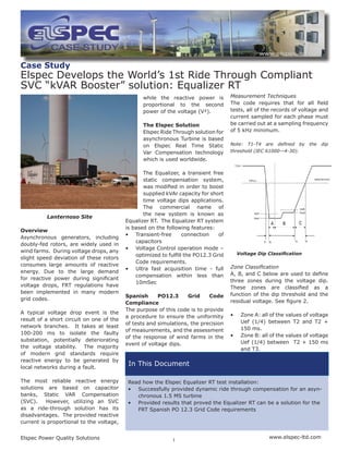
- 1. Elspec Power Quality Solutions www.elspec-ltd.com 1 In This Document while the reactive power is proportional to the second power of the voltage (V²). The Elspec Solution Elspec Ride Through solution for asynchronous Turbine is based on Elspec Real Time Static Var Compensation technology which is used worldwide. The Equalizer, a transient free static compensation system, was modified in order to boost supplied kVAr capacity for short time voltage dips applications. The commercial name of the new system is known as Equalizer RT. The Equalizer RT system is based on the following features: • Transient-free connection of capacitors • Voltage Control operation mode – optimized to fulfill the PO12.3 Grid Code requirements. • Ultra fast acquisition time - full compensation within less than 10mSec Spanish PO12.3 Grid Code Compliance The purpose of this code is to provide a procedure to ensure the uniformity of tests and simulations, the precision of measurements, and the assessment of the response of wind farms in the event of voltage dips. Case Study Elspec Develops the World’s 1st Ride Through Compliant SVC “kVAR Booster” solution: Equalizer RT Lanternoso Site Overview Asynchronous generators, including doubly-fed rotors, are widely used in wind farms. During voltage drops, any slight speed deviation of these rotors consumes large amounts of reactive energy. Due to the large demand for reactive power during significant voltage drops, FRT regulations have been implemented in many modern grid codes. A typical voltage drop event is the result of a short circuit on one of the network branches. It takes at least 100-200 ms to isolate the faulty substation, potentially deteriorating the voltage stability. The majority of modern grid standards require reactive energy to be generated by local networks during a fault. The most reliable reactive energy solutions are based on capacitor banks, Static VAR Compensation (SVC). However, utilizing an SVC as a ride-through solution has its disadvantages. The provided reactive current is proportional to the voltage, Measurement Techniques The code requires that for all field tests, all of the records of voltage and current sampled for each phase must be carried out at a sampling frequency of 5 kHz minimum. Note: T1-T4 are defined by the dip threshold (IEC 61000—4-30). Zone Classification A, B, and C below are used to define three zones during the voltage dip. These zones are classified as a function of the dip threshold and the residual voltage. See figure 2. • Zone A: all of the values of voltage Uef (1/4) between T2 and T2 + 150 ms. • Zone B: all of the values of voltage Uef (1/4) between T2 + 150 ms and T3. Voltage Dip Classification Read how the Elspec Equalizer RT test installation: • Successfully provided dynamic ride through compensation for an asyn- chronous 1.5 MS turbine • Provided results that proved the Equalizer RT can be a solution for the FRT Spanish PO 12.3 Grid Code requirements
- 2. Elspec Power Quality Solutions www.elspec-ltd.com2 • Zone C: all of the values of voltage Uef (1/4) between T3 and the lesser of the following values, T4 and T3 + 150ms Methodology for Calculating Power Power consumption is expressed in normalized value (p.u.) to the registered nominal power of the WTG tested. Similarly, energy consumption values are expressed in normalized values of power by time unit in milliseconds (ms p.u.) The voltage and current levels registered in the test, as well as data obtained from simulations must be included in the report form as per Table 1. The Elspec Test The 1.5 MW turbine can be supplied with an automatic power factor correction system that makes it compliant with even very demanding grid codes; the turbine has ride- through capacity for all normal faults. Test Setup The RTC and the Equalizer RT containers were located in adjacent to the Turbine. The RTC container was connected to the medium voltage (20kV) in order to simulate voltage dips according to the Spanish Grid Code PO12.3. Elspec Equalizer RT system was connected at the turbine transformer output (690V). Elspec Equalizer RT container comprises also 4 Elspec G4K BLACKBOX model EG4420, advanced power analyzer in order to carry out measurements in the following network points: • Grid input to the RTC container system 20kV. • RTC container system output to the turbine: approximately 20% of the medium voltage (during the dips). • Transformer output of the turbine - 690V (measurements of the turbines generator and the Equalizer RT system). • Equalizer RT system output The measurements were carried out continuously during the test period. All network parameters were recorded cycle by cycle at 1024 samples per cycle for voltages and 256 samples per cycle for currents. For more details, please refer to the G4k catalog web site www.elspec-ltd.com at products and services. *)The value is changed in proportion to the voltage Energy and Power Registry Low Power Conditions magnitude Test Description Low Power Low Power Test (10% - 30% of nominal) The test comprises six tests as follows: Three sequential unbalanced tests Three sequential balanced tests The following table provides the reactive current and energy values which were required from the Equalizer RT system in order to comply with PO12.3. The values were confirmed by qualified company for the PO12.3 test procedure, which was carried out by the supplier Ride Through test container. Zone Reactive Current Reactive Energy A Above 2000A Above 800kVAr B Above 2000A Above 800kVAr C 2000A to 3500A 800 to 3300kVAr (*) (*)The value is changed in proportion to the voltage magnitude Low Power Measurements
- 3. Elspec Power Quality Solutions www.elspec-ltd.com3 Low Power Results The effect of the Equalizer RT on the Grid at low power mode of operation of the turbine (<30%) is seen in Figure 4. It illustrates the consumption of the reactive energy and the current in MV at the connection point of the turbine to the Grid. It also provides the current waveform of the Equalizer RT in Low Voltage. Without Equalizer RT, the consumption of reactive energy during Zone C almost reached 3 MVAR. With the Equalizer RT, it reduced to less than 500kVAR. In Zone A & B, the Equalizer RT contributes substantial reactive energy to the Grid (above 800kVAR). High Power Test (more than 1300kW) The test comprises the same set of parameters as the Low Power Test. Three sequential unbalanced tests Three sequential balanced tests Equalizer RT solution: With and Without High Power Equalizer RT Measurements (*)The value is changed in proportion to the voltage magnitude
- 4. International Elspec Ltd. P.O. Box 3019 4 HaShoham St., Zone 23 Caesarea Industrial Park 38900, Israel Tel: +972-4-6272-470 Fax: +972-4-6272-465 email: info@elspec-ltd.com North America Elspec North America, Inc. 500 West South Street Freeport, IL 61032 USA Tel: +1-815-266-4210 Fax: +1-815-266-8910 email: info@elspecna.com Europe Elspec Portugal Lda. Zona Industrial 1a Fase 4900-231 Chafe Viana do Castelo Portugal Tel: +315-258-351-920 Fax: +315-258-351-607 email: info@elspecportugal.com This document contains Elspec proprietary material. The information contained in this document is believed to be reliable and accurate. ©2008 Elspec Ltd. All rights reserved. SMC- The following table provides the relative current values which were required from the Equalizer RT system in order to comply with the PO12.3. The values were confirmed by a qualified company for PO12.3 algorithm. Zone Reactive Current Reactive Energy A Above 3300A Above 1500kVAr B Above 3300A Above 1500kVAr C 3500A-5500A 1500-6500kVAr (*) (*)The value is changed in proportion to the voltage magnitude High Power Results The effect of the Equalizer RT on the Grid at high power mode of operation of the turbine (>1300kW) is seen in Figure 6. It illustrates the consumption of the reactive energy and the current in MV at the connection point of the turbine to the Grid. It also provides the active power of the turbine. Without the Equalizer RT, the consumption of reactive energy during Zone C almost reached 7 MVAR. With the Equalizer RT, it reduced to almost zero. In Zone A & B, the Equalizer RT contributes substantial reactive energy to the Grid (above 1500kVAR). High Power Conditions High Power Results