
Recommended
More Related Content
What's hot
What's hot (20)
Similar to Design of a steel frame according to Eurocode standards
Similar to Design of a steel frame according to Eurocode standards (20)
More from Maria João Espada
More from Maria João Espada (6)
Recently uploaded
Recently uploaded (20)
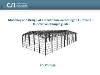
Design of a steel frame according to Eurocode standards
- 1. 1 Design of a steel frame according to Eurocode – SAP2000 Training Program CSI Portugal & Spain
- 2. 3. Portal frames 1. Architectural and environmental conditions 2. Architecture 7. Actions 4. Roof and walls sheeting 5. Purlins 8. Actions combinations 6. Bracing systems 2CSI Portugal - Design of a Steel Frame Contents of Frame Design Example Contents 9. Steel sheeting design
- 3. 10. Modeling the structure 3CSI Portugal - Design of a Steel Frame Contents of Frame Design Example 15. Members automatic ULS check 14. Members buckling lengths 11. Load assignments 16. Members automatic design 12. Frame buckling analyses Contents (cont.) 13. Equivalent imperfection forces 17. SLS check
- 4. Objective: Design steel structure for indoor sports facility in the suburbs of the city of Évora (Portugal) with a covered area of 60 x 30 m2 Arquitectural requirements: • Soil suitable for slallow foundations • Materials: steel S275 for framework and S235 for roof and wall sheeting concrete C25/30 rebar reinforcement: S400 4CSI Portugal - Design of a Steel Frame 1. Architectural and Environmental Conditions
- 5. 5CSI Portugal - Design of a Steel Frame 2. Architecture 1) Flat frame imin = 0.5-1% 2) Duopitch or gable frame Slope decreases moments in the middle region of the rafters Roof shapes for drainage
- 6. 6CSI Portugal - Design of a Steel Frame 2. Architecture 3) Single slope, monopitch or shed frame 4) Parabolic or circular frame 5) Multispan frame
- 7. Chosen solution: 15 steep duo-pitch roof shape 7CSI Portugal - Design of a Steel Frame 2. Architecture Portal frame components:
- 8. 8CSI Portugal - Design of a Steel Frame 3. Portal Frames Portal frames structural behaviour Simply supported because of (i) support conditions or (ii) variable inertia 1) Simply supported beam 2) Articulated (pinned) frame Isostatic
- 9. 9CSI Portugal - Design of a Steel Frame 3. Portal Frames 3) Rigid connections frame 4) Cable stayed frame Very slender rafters prone to up-lifting by wind Hiperstatic Plastic stress-resultant redistributions possible
- 10. 1) Hot-rolled I- or H-section profiles 2) Welded beams (composed of unperforated plates) 10 3. Portal Frames Support moments higher than span in rigid connections frame Solution: use knee joint knee joint CSI Portugal - Design of a Steel Frame Rafter solutions L < 30 ~ 35 m 3) Tapered beams: simply supported rafter Simply supported beam For simply supported rafters or articulated frames
- 11. 4) Perforated beams: honeycomb 11CSI Portugal - Design of a Steel Frame 3. Portal Frames Increased bending resistance and stiffness maintaining shear resistance Tubes can pass throught the beams Higher costs (cuting and welding) Usually pinned beams (may not resist bending + shear at supports) 5) Cellular beams: uniform or tapered Tapered sectionUniform sectionFabrication L0/h = 15-30Similar to honeycomb + esthetics
- 12. 6) Planar trusses Constant depth Variable depth 7) Spatial trusses Cubes or tetrahedron shape Complex connections Hollow section profiles Light solutions for long spans Reduces bracing required Boeing factory Olympic pool 12CSI Portugal - Design of a Steel Frame 3. Portal Frames L0/h = 5-6L0/h = 10-12 20 < L < 100 m
- 13. Extreme rafter slenderness 8) Cable-stayed solutions Additional column compression Solution for large spans Roof weight vs up-lifting forces Possible up-lift due to wind forces 13CSI Portugal - Design of a Steel Frame 3. Portal Frames
- 14. Chosen solution: Rafter: planar truss; RHS profiles; welded connections Column: HEA or HEB 14CSI Portugal - Design of a Steel Frame 3. Portal Frames Rigid connection (bolted) Rigid connection (bolted)
- 15. • IPE, Z, U or channel purlins 15CSI Portugal - Design of a Steel Frame 3. Portal Frames 1) Regular (5-7 m) • Moderate actions • Economical solution 2) Reduced (< 5 m) • Very high loads (wind, snow, insulation materials, soil) 3) Increased (> 7 m, < 12 m) • Trussed purlins • Interior constraints to column locations • Roof sheeting suitable for long spans Portal frames spacing 6 m Chosen spacing:
- 16. Elements: 2) Trapezoidal steel sheeting: longer spans, lighter, thermal insulation possible, better esthetics, enough longitudinal strength for purlins bracing 3) Corrugated aluminium sheeting: very light, corrosion resitant, expensive, too deformable (shorter spans), high noise in heavy rain 4) Translucid plastics (polycarbonate): low strength (shorter spans), sensitive to sunlight exposure (become brittle), combustible, very light 16CSI Portugal - Design of a Steel Frame 4. Roof and Walls Sheeting 1) Corrugated fibre-cement: economical, brittle, unesthetical, heavy, low insulation, asbestos fibres are unhealthy Sheeting: (i) Sheeting (iii) Drainage elements (ii) Purlins (iv) Joint elements and purlins bracing Steel sheeting with thermal insulation; 1.5 m spans Adopted solution:
- 17. Main: • Transmit roof loads to the rafters • Brace the rafters upper chords or flanges Purlin solutions: - Hot rolled (IPE, UNP)1) Spans up to 9 m - Cold-formed (Z-, channel or lipped channel section) 17CSI Portugal - Design of a Steel Frame 5. Purlins 2) Spans up to 15 m - planar or spatial truss beams - Planar beam with rods - Planar beam with profiles Functions: Optional: • Brace the rafters lower chords (indirectely through the lower chords bracing rods) • Brace the portal frames for out-of-plane displacements • Transmit longitudinal horizontal endwall loads to the bracing system UNP (channel) profiles Chosen solution:
- 18. 18CSI Portugal - Design of a Steel Frame 5. Purlins Connection to the rafter: Ovalisation: elongated bolt hole to function as a movement joint for thermal action Types of connections to the rafters: (i) lower flange bolted, (ii) plate bolted to the web, (iii) use a channel InclinedChosen configuration: Purlin configurations: Vertical Inclined • For predominatly vertical loads (snow or life) • For predominatly normal loads (wind) • Easier to execute
- 19. 19CSI Portugal - Design of a Steel Frame 5. Purlins 1) Simply supported Supports and joints: 2) Gerber 3) Continuous beam 4) Two-span beam Purlin connection: Two-span beam in alternated configuration (see next slide) Chosen solution:
- 20. 20CSI Portugal - Design of a Steel Frame 5. Purlins Two-span alternated configuration reactions: Purlin Rafter Two-span non- alternated: One-span: 1.875/2 6.25/2 3.75/2 6.25/2 3.75/2 2.5/2 5/2 5/2 5/2 5/2 Two-span alternated: • Distributes more uniformly the loads on the rafters
- 21. 21CSI Portugal - Design of a Steel Frame 5. Purlins • Determined by the sheeting span (1.2-2 m normally) • Possibility of reduced spacing in localised zones (e.g., where wind loads are higher) Spacing 1.5 m Chosen spacing:
- 22. 3) Purlins bracing 2) Rafter lower chords bracing 1) Frame longitudinal and transversal bracing 22CSI Portugal - Design of a Steel Frame 6. Bracing systems
- 23. Transversal bracing 23CSI Portugal - Design of a Steel Frame 6. Bracing systems • resists longitudinal horizontal loads (e.g., wind loads in the enwalls) • prevents global buckling Longitudinal bracing • resists transversal horizontal loads • prevents global buckling • only used in highly deformable frames• braces the rafters (absorbs their imperfection equiv. loads) Central • thermal action generates negligible axial forces • purlins under compression for wind loads (additional beams may be necessary) Double-sided • thermal action may result in high axial forces • purlins are not subjected to compression due to wind • No longitudinal bracing Chosen bracing: • Transversal double-sided
- 24. Rafter lower chord bracing 24CSI Portugal - Design of a Steel Frame 6. Bracing systems • May be uniformly spaced or more concentrated on the most compressed zones • Diagonal at 45 Chosen bracing: Perpendicular • works only in tension • must be fixed at both ends endwall column chord bracing rod Diagonal • normally at q=45 • low q: less flexible but may not work in compression • transfers the instability loads to the purlins • high q: more flexible due to purlin bending rafter purlin chord bracing rod
- 25. • Absobs the roof in-plane load component • Limits purlin minor axis bending • Reduces purlins lateral buckling length 25CSI Portugal - Design of a Steel Frame 6. Bracing systems Bracing rod, tie rod or sag bar: Bracing rod anchor: a) Ridge (eave) purlins absorb the rod tension b) Diagonal rods transmit the tension to the rafters Purlins bracing • Connected using nuts and washers
- 26. 2) Live EN 1991: Part 1-1 3) Wind actions 4) Thermal actions EN 1991: Part 1-4 EN 1991: Part 1-5 26CSI Portugal - Design of a Steel Frame 7. Actions 1) Dead EN 1991: Part 1-1
- 27. Dead 3 77 mkNs Structural elements: Note: members dead weight is automatically determined in SAP2000 Sheeting self-weight: 2 05.0 mkNqEd Live 2 4.0 mkNqEd Roof: kNQEd 1 (distributed) (concentrated) EN 1991-1-1 Table 6.10 H category – roof not accessible except for normal maintenance and repair EN 1991-1-1 Table A.4 27CSI Portugal - Design of a Steel Frame 7.1 Dead and Live Actions
- 28. 28CSI Portugal - Design of a Steel Frame 7.2 Wind Action 222 /456.02725.1 2 1 2 1 mkNvq bb Basic velocity pressure: Wind force: refppEkw AcqF . peak velocity pressure differential pressure coeficient reference area Notes: • Fw.Ed is normal to the surface • friction force can be neglected when: A// 4A∟ 2 2 // 2 3 aA aA e.g.: Terrain category: III (regular cover of vegetation or buildings) 2 /903.0456.098.1)15()15( mkNqmcmq bep Peak velocity pressure: smvccv bseasondirb /27270.10.10. Basic wind velocity: season factor directional factor Évora county (Zone A): vb.0=27 m/s (National Annex, Table NA.I) Peak velocity pressure (qp) fundamental velocity
- 29. External pressure coeficient (cpe) 3.0,2.0 pic (both should be considered) Otherwise: 29CSI Portugal - Design of a Steel Frame 7.2 Wind Action Internal pressure coeficient (cpi) If area of opennings in each face is known: openingsallofArea 0cwithopeningsofArea pe Two wind directions are considered: º0q º90q
- 30. 2 wind directions × 2 internal pressures = 4 wind loading cases Differential pressure coeficient (cp): 30CSI Portugal - Design of a Steel Frame 7.2 Wind Action Number of loading cases: pipep ccc
- 31. Temperature in a element according to EN 1991-1-5: neglected (elements are thin-walled) 31CSI Portugal - Design of a Steel Frame 7.3 Thermal Action 1) Uniform 2) Linearly varying 3) Nonlinear neglected (elements are flexible for bending) Uniform temperature variation of an element: 0TTTu average temp. of an element in summer or winter considering a temp. profile average temp. during construction Example: 2 outin TT T
- 32. (bright light surface) Location: Évora CT CT º5 º45 min max 03 T CT º200 32CSI Portugal - Design of a Steel Frame 7.3 Thermal Action Évora county (Zone A) (National Annex, Tables NA.I and NA.II) National Annex, Table NA.5.1 CT CT º18 º25 2 1 Inside temp. Summer Winter Members temp. CTTTT º355.0 13max Temp. variation CTTT CTTT º5.13 º15 0 0 Outside temp. Notes: (construction during spring or automn)Temp. profile is deemed linear (conservative) CTTT º5.65.0 2min Uniform temperature variation for the steel members:
- 33. DEAD CB_LIVE ULS_STR/GEO-B1_0 1.35 1.5 0.9 ULS_STR/GEO-B1_1 1.35 1.5 0.9 ULS_STR/GEO-B1_2 1 1.5 0.9 ULS_STR/GEO-B1_3 1 1.5 0.9 ULS_STR/GEO-B1_4 1.35 1.5 ULS_STR/GEO-B1_5 1 1.5 ULS_STR/GEO-B1_6 1.35 1.5 0.9 ULS_STR/GEO-B1_7 1.35 1.5 0.9 ULS_STR/GEO-B1_8 1.35 1.5 0.9 ULS_STR/GEO-B1_9 1.35 1.5 0.9 ULS_STR/GEO-B1_10 1.35 1.5 0.9 ULS_STR/GEO-B1_11 1.35 1.5 0.9 ULS_STR/GEO-B1_12 1.35 1.5 0.9 ULS_STR/GEO-B1_13 1.35 1.5 0.9 ULS_STR/GEO-B1_14 1 1.5 0.9 ULS_STR/GEO-B1_15 1 1.5 0.9 ULS_STR/GEO-B1_16 1 1.5 0.9 ULS_STR/GEO-B1_17 1 1.5 0.9 ULS_STR/GEO-B1_18 1 1.5 0.9 ULS_STR/GEO-B1_19 1 1.5 0.9 ULS_STR/GEO-B1_20 1 1.5 0.9 ULS_STR/GEO-B1_21 1 1.5 0.9 ULS_STR/GEO-B1_22 1.35 1.5 ULS_STR/GEO-B1_23 1.35 1.5 Load pattern LIVE WIND_2WIND_1 WIND_3 WIND_4 TEMP+ TEMP- • 50 combinations • 7 are deemed the most unfavourable (green) 33CSI Portugal - Design of a Steel Frame 8. Actions Combinations Actions combinations according to EN 1990:
- 34. Note: automatic load combinations obtained using CTM 1.0 software CB_WIND3 ULS_STR/GEO-B1_24 1.35 1.5 CB_WIND4 ULS_STR/GEO-B1_25 1.35 1.5 CB_WIND1 ULS_STR/GEO-B1_26 1 1.5 CB_WIND2 ULS_STR/GEO-B1_27 1 1.5 ULS_STR/GEO-B1_28 1 1.5 ULS_STR/GEO-B1_29 1 1.5 ULS_STR/GEO-B1_30 1.35 0.9 1.5 ULS_STR/GEO-B1_31 1.35 0.9 1.5 ULS_STR/GEO-B1_32 1.35 0.9 1.5 ULS_STR/GEO-B1_33 1.35 0.9 1.5 ULS_STR/GEO-B1_34 1.35 0.9 1.5 ULS_STR/GEO-B1_35 1.35 0.9 1.5 ULS_STR/GEO-B1_36 1.35 0.9 1.5 ULS_STR/GEO-B1_37 1.35 0.9 1.5 ULS_STR/GEO-B1_38 1 0.9 1.5 ULS_STR/GEO-B1_39 1 0.9 1.5 ULS_STR/GEO-B1_40 1 0.9 1.5 ULS_STR/GEO-B1_41 1 0.9 1.5 ULS_STR/GEO-B1_42 1 0.9 1.5 ULS_STR/GEO-B1_43 1 0.9 1.5 ULS_STR/GEO-B1_44 1 0.9 1.5 ULS_STR/GEO-B1_45 1 0.9 1.5 CB_TEMP1 ULS_STR/GEO-B1_46 1.35 1.5 CB_TEMP2 ULS_STR/GEO-B1_47 1.35 1.5 ULS_STR/GEO-B1_48 1 1.5 ULS_STR/GEO-B1_49 1 1.5 DEAD Load pattern LIVE WIND_2WIND_1 WIND_3 WIND_4 TEMP+ TEMP- 34CSI Portugal - Design of a Steel Frame 8. Actions Combinations
- 35. 2 max.. /03.25.1903.05.1 mkNcqq ppQEdW Maximum wind load: Permissable loads [kN/m2] 35CSI Portugal - Design of a Steel Frame 9. Steel Sheeting Design Trapezoidal sheet sheeting: • 0.5 mm Chosen thickness: 2 /41.2 mkNqRd Thickness: 0.5 mm Span: 1.5 m Permissable load: 03.241.2 . EdWRd qq OK (up-lifting)
- 36. Sheeting distributed self-weight: 6 m long sheets with 0.3 m overlaping 5% of weight increase due to joint additional elements 23 /051.07.5681.9107.405.1 mkNpEd sheet mass per sqr meter 36CSI Portugal - Design of a Steel Frame 9. Steel Sheeting Design Actions on the purlins Sheeting self-weight: mkNLpp EdEdG 077.05.1051.0. Uniform life load: mkNLqp EdEdQ 58.0º15cos5.14.0cos. Maximum wind load: mkNLqp EdWEdW 05.35.103.2..
- 37. Portal frame column Sheeting equivalent beam Lower chord bracing Purlin Transversal bracing Endwall column Girt or wall purlin Rafter truss 37CSI Portugal - Design of a Steel Frame 10. Modeling the Structure Purlins bracing rod Girts bracing rod Modelled members:
- 38. 38CSI Portugal - Design of a Steel Frame 10. Modeling the Structure 1) Stiffness model • Longitudinal purlins and sheeting axially fixed 2) Strength model • All purlins axially released (simply supported) • Purlins connect the rafters to the transversal bracing contributing to their stability • Purlins do not transmit thermal loads, since they are provided with movement joints (slotted connections) Objective: perform buckling analyses Objective: determine stress resultants for member design Two frame models are used:
- 39. Local axes of roof and wall purlins: 1- axial 2- major deflection 3- minor deflection Axis 3 (cyan) of UNP profile should be pointing upwards to avoid dirt or water accumulation in the profile Axis 2 (green) should be pointing in-wards to make the application of wind loads easy 39CSI Portugal - Design of a Steel Frame 10. Modeling the Structure
- 40. Portal frame Rafter (planar truss) Column 40CSI Portugal - Design of a Steel Frame 10. Modeling the Structure Option 2: model members with the longest length possible Option 1: model members with the shortest length possible Advantages Disadvantages • buckling lengths are easily identified • buckling lengths may be more difficult to determine • it is necessary to determine the imperfection forces (and eventual P- effects) in all minor nodes • it is only necessary to determine the imperfection forces and P- effects in the major nodes Major node Minor node • only possible if the member is uniform (continuous) • Option 2 Chosen option:
- 41. 10. Modeling the Structure • Sheeting contributes to stabilize the rafters lower chords Rafter lower chord P- instability: Equivalent inertia beam: (spaced 1 m) Frame model: Purlin 41CSI Portugal - Design of a Steel Frame Steel sheeting modeling
- 42. 42CSI Portugal - Design of a Steel Frame 11. Load Assignments Dead Live
- 43. 43CSI Portugal - Design of a Steel Frame 11. Load Assignments Wind 1 Wind 2
- 44. 44CSI Portugal - Design of a Steel Frame 11. Load Assignments Wind 3 Wind 4
- 45. 45CSI Portugal - Design of a Steel Frame 11. Load Assignments The thermal actions on the purlins can be ignored because they are provided with movement joints Thermal CT º0 Purlins: Rafters, columns and bracing: CT º15
- 46. Frame buckling loads may be determined using equations (5.1) and (5.2) of EC3-1-1: kNVEd 120 b) Transversal buckling mH 0015.0max. 101.61 0015.0 11 120 1 HEd cr h V H 46CSI Portugal - Design of a Steel Frame 12. Frame Buckling Analysis • Equation (5.2) is only valid for not significantly compressed and shallow ( 26 ) rafters )2.5()1.5( HEd cr Ed cr cr h V H F F • Average compression force per column (LIVE load combination): • SAP2000 stiffness model is used and 1st order analyses are performed to determine H a) Longitudinal buckling 104.76 0012.0 11 120 1 HEd cr h V H mH 0012.0max. No global 2nd order effects need to be considered
- 47. 47CSI Portugal - Design of a Steel Frame 12. Frame Buckling Analysis The lower chords buckling length may be verified using a buckling analysis: • Only part of the structure needs to be analysed (decreases number of buckling modes to be checked) • Additional restraints substitute the transversal bracing effect • Useful to check if lower chord bracing has enough stiffness to function propertly • Use stiffness model (purlins and sheeting axially fixed) • Negative buckling loads are ignored lower chord bracing additional restraint • Buckling length is the distance between inflection points of the buckled lower chord Bracing system must resist the effect of member imperfections (eventually amplified by 2nd order effects) (EC3-1-1: 5.3.3) compressed chord braced point
- 48. 48CSI Portugal - Design of a Steel Frame 12. Frame Buckling Analysis a) LIVE load combination Buckling mode 2: 37.72. b lower chord buckling bracing almost 100% effective • Buckling length may be considered as the distance between bracing points • Bracing must resist imperfection forces 58.114. b • Sheeting shear stiffness likely to prevent this mode Buckling mode 4: upper chord buckling Chord buckling modes
- 49. 49CSI Portugal - Design of a Steel Frame 12. Frame Buckling Analysis b) WIND3 load combination 51.134. b • Sheeting shear stiffness likely to prevent this mode Buckling mode 4: upper chord buckling Buckling mode 1: 08.71. b lower chord buckling bracing almost 100% effective • Buckling length may be considered as the distance between bracing points • Bracing must resist imperfection forces Chord buckling modes
- 50. 50CSI Portugal - Design of a Steel Frame 13. Equivalent Imperfection Forces Lower chord bracing design Member length: mL 54.1 One took advantage of bracing compressive stiffness therefore it must be checked for its buckling strength Max. chord compressive force (LIVE comb): kNNEd 310 Axial force (lower chord): Braced pointLateral force: kNNEd 775.025.02 Imperfection: 005.0 Average comp. force: EdN25.0 Bracing axial force: kNkNN Rdb 10.193.65. kN10.1º45cos775.0 OKBracing buck. strength: Comp. (L50x5)
- 51. 51CSI Portugal - Design of a Steel Frame 13. Equivalent Imperfection Forces 2) Columns initial geometric imperfection 76.06115.0115.0 mm (EC3-1-1: 5.3.3) mmLe m 175001176.05000 number of members to brace Slotted hole ovalisation of +/- 4 mm every 12 m md 24 mm812244 1) Bolt hole ovalisation (slotted connection) effect • The purlins only work axially for displacements higher than the ovalisation Purlin m11 3) The effect of the ovalisation must be added to the imperfection mmee equiv 258170.0 Instability loads on the transversal bracing
- 52. 52CSI Portugal - Design of a Steel Frame 13. Equivalent Imperfection Forces 4) Bracing force kNVEd 120 (LIVE load comb.) Compressive force per column: Supported by right bracingSupported by left bracing Bracing force applied in each bracing system corner: kN LeVF equivEdEd 64.11110251206 6 3 .0 Neglectable (less than 1% of the wind load) 5) Effect of ovalisation displacement in columns kNmH /0072.0 kN HH 11.1 0072.0108 3 (from SAP2000 strength model) to be applied on top of each column
- 53. 53CSI Portugal - Design of a Steel Frame 13. Equivalent Imperfection Forces Columns equivalent geometric imperfections 866.02115.0115.0 mm mh 0 Imperfection equivalent forces mm 115.0 132with2 hh h 32h Portal frame in-plane imperfection mh 15 kNNEd 35.012000289.0 00289.0866.0 3 2 200 1 20010
- 54. 54CSI Portugal - Design of a Steel Frame 14. Members Buckling Lengths In SAP2000 the buckling lengths of members are determined by: Buckl. length = K factor × L factor × Member length There are 3 types of L factors: • major axis L factor • minor axis L factor • lateral torsional L factor Related to the rotational stiffenesses at the member ends Related to the intermediate bracing There are 5 types of K factors: • K1.z – minor plane in braced mode • K1.y – major plane in braced mode • K2.y – major plane in sway mode • K2.z – minor plane in sway mode • KLT – lateral torsional mode - K2 (sway mode) values are used by default Note:
- 55. 55CSI Portugal - Design of a Steel Frame 14. Members Buckling Lengths Determination of K factors according to Annex E of old EC3: ),(KfactorK 21 22212 12111 KKKK KKKK cc cc • In SAP2000 the K factors are determined from the components of the beams stiffenesses in the considered plane: i iicc KKK q cos11 i iicc KKK q cos22 Note: - If ‘P-Delta done’ is checked, K2.y= K2.z= KLT=1 Unbraced Braced
- 56. 56CSI Portugal - Design of a Steel Frame 14. Members Buckling Lengths L factor automatic determination • In SAP2000 the effect of intermediate bracing due to other bars intersecting the member is incorporated by the L factor: (i) Only members with q 60 w.r.t. the buckling plane are considered as bracing elements (ii) Stiffness or strength requirements for bracing members are not checked (iii) L factor is equal in minor axis buckling and lateral torsional buckling º307.0 º301 (minor)factorL º607.0 º601 (major)factorL q q q q if if if if
- 57. 57CSI Portugal - Design of a Steel Frame 14. Members Buckling Lengths 1st Overwrite – Lateral Bracing Overwriting K factors and L factors • For L factors for minor plane and lateral torsional buckling • Point bracing and/or uniform bracing on top and/or bottom flange are possible • Top or bottom always braces minor plane buckling • Top or bottom only braces lateral buckling if the respective flange is under compression 2nd Overwrite – Direct Overwrite • For all K factors and L factors • Overwrites the lateral bracing overwrite if L factors are specified • L factor = maximum unbraced length
- 58. 58CSI Portugal - Design of a Steel Frame 14. Members Buckling Lengths Lower chord buckling lengths m5.1 m5.4 Member length: Diagonal nodes spacing: Bracing spacing: Manually determined factors: 305.0752.145.4LTB)(FactorL 305.0752.145.4Minor)(FactorL 102.0752.145.1Major)(FactorL Automatically determined factors: OK mL 752.14
- 59. 59CSI Portugal - Design of a Steel Frame 14. Members Buckling Lengths Upper chord buckling lengths m5.1 m5.1 Member length: Diagonal nodes spacing: Purlins spacing: Manually determined factors: 098.0261.155.1LTB)(FactorL 098.0261.155.1Minor)(FactorL 098.0261.155.1Major)(FactorL mL 261.15 Automatically determined factors: OK
- 60. 60CSI Portugal - Design of a Steel Frame 14. Members Buckling Lengths Purlins buckling lengths m1 Member length: Equiv. Sheeting bars spacing: Manually determined factors: 5.063LTB 5.063Minor 166Major FactorL 1LTB 1Minor 1Major sway)-(non FactorK mL 6 Automatically determined factors: Not OKOK Overwrites: • Equiv. sheeting rods don’t provide lateral bracing. L Factor Minor and LTB are 0.5 due to the bracing rods Braced nodes spacing: m3 OK Factors after overwrite: OK
- 61. Automatically determined factors: OKNot OK 61CSI Portugal - Design of a Steel Frame 14. Members Buckling Lengths Portal frame columns m932.0 m5.1Member length: Chord nodes spacing: Girts spacing: Manually determined factors: 136.0115.1LTB 136.0115.1Minor 915.011932.011Major FactorL 1LTB 1Minor 7.0~5.0Major sway)-(non FactorK mL 11 OK Factors after overwrite: OK Overwrites: • Column has a K Factor Major between 0.5 (fixed-fixed) or 0.7 (fixed-pinned). The latter value is adopted conservatively
- 62. 62CSI Portugal - Design of a Steel Frame 14. Members Buckling Lengths Endwall columns m5.1Member length: Girts spacing:mL 14 OK Factors after overwrite: OK Automatically determined factors: OKNot OK Overwrites: • Column has a major K Factor of 0.7 (fixed-pinned). Manually determined factors: 107.0145.1LTB 107.0145.1Minor 11414Major FactorL 1LTB 1Minor 7.0Major sway)-(non FactorK
- 63. 63CSI Portugal - Design of a Steel Frame 15. Members Automatic ULS Check • Use SAP2000 frame strength model Check members for collapse ULS Steel frame design preferences: • Interaction factors method (EC3-1-1: Annex A and B) • Check ‘P-Delta done’ if 2nd order effects at the nodes are already determined (Sway K Factors become unitary) • Set design code and coutry • Ignore seismic code (EC8) • Demand/Capacity ratio limit should be 1 for ULS but may be user specified
- 64. 64CSI Portugal - Design of a Steel Frame 16. Members Automatic Design 2) Select design groups Design -> Steel Frame Design -> Select Design Groups 3) Start design of structure Design -> Steel Frame Design -> Start Design/Check of Structure • If optimised member sections are significantly smaller than the original ones, it may be necessary to run the buckling analyses again with the new sections Note: 1) Assign Auto select section properties to the groups Define -> Section Properties -> Frame Sections Add New Property -> Auto Select List
- 65. Action combinations for SLS: Serviceability limit state (SLS): Limitation of vertical and horizontal displacements (National Annex EN 1993-1-1) DEAD LIVE WIND2 TEMP SLS_CARAC_0 1 1 0.6 SLS_CARAC_1 1 1 SLS_CARAC_2 1 1 0.6 SLS_CARAC_3 1 1 SLS_CARAC_4 1 0.6 1 SLS_CARAC_5 1 1 65CSI Portugal - Design of a Steel Frame 17. SLS Check Note: automatic load combinations obtained using CTM 1.0 software 2) Horizontal displacements: (on columns top) (frames without lift equipment)150limit h mm 073.015011009.0 limitmax Column (HE400A): 1) Vertical displacements: (of every beam) 200limit L (general roof cathegory) mm 030.02006025.0 limitmax Purlins (UPN 140): mm 150.020030027.0 limitmax Rafter: Endwall column span (HE300A): mm 070.020014015.0 limitmax