
Recommended
More Related Content
Similar to CIM INTRODUCTION UNIT 1.pdf
Similar to CIM INTRODUCTION UNIT 1.pdf (20)
Recently uploaded
Recently uploaded (20)
CIM INTRODUCTION UNIT 1.pdf
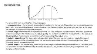
- 1. PRODUCT LIFE CYCLE The product life cycle consists of the following stages : 1) Introduction stage : The product is produced and introduced in the market . The product has no competitors at this point. Sales may remain low because it takes time to accept the new product. Marketing costs are high. At this stage, the company usually loses money on the product. 2) Growth stage : The market has accepted the product. The sales and profit begin to increase. This rapid growth can be continued only by the maintenance of product quality. The company should make improvements to the product to stay competitive. This increased competition results in decreasing the product price. 3) Maturity stage : During this stage, sales will reach their peak. The costs are decreased as a result of increased production volumes. Other competitors enter the market with alternative solutions. The company should spend increasing amount on salespromotion. 4) Decline stage : In the decline stage, sales and profit will begin to decline as the product reaches its saturation point. The product is phased out of the market due to the decrease in sales, market saturation, high competition, and changing customer needs.
- 3. S.N0 SEQUENTIAL ENGINEERING CONCURRENT ENGINEERING 1 Sequential engineering is the term used to explain the method of production in a linear system. The various steps are done one after another, with all attention and resources focused on that single task In concurrent engineering, various tasks are handled at the same time, and notes essentially in the standard order. This means that info found out later in the course can be added to earlier parts, improving them, and also saving time 2 Sequential engineering is a system by which a group within an organization works sequentially to create new products and services Concurrent engineering is a method by which work several groups within an organization simultaneously to create new products and services. 3 The sequential engineering is a linear product design process during which all stages of manufacturing operate in serial. The concurrent engineering is a non linear Product design process during which all stages of manufacturing operate at the same time. 4 Both process and product design run in serial and take place in the different time. Both process and product design run in serial and take place in the different time 5 Process and Product are not matched to attain optimal matching Process and Product are co ordinated to Attain optimal matching of requirements for effective quality and delivery 6 Decision making done by only group of experts Decision making involves full team Involvement.
- 4. ROLE OF COMPUTER IN DESIGN
- 11. HOMOGENEOUS TRANSFORMATIONS • The conversion of a two-dimensional co-ordinate pair (X, Y) into a 3-dimensionalvector can be achieved by representing the point as [X Y 1]. • After multiplying this vector by a 3 X 3 matrix, another homogeneous row vector is obtained [X1 Y1 1]. The first two terms in this vector are the co- ordinate pair which is the transform of (X, Y). • This three dimensional representation of a two dimensional plane is called homogeneous coordinates and the transformation using the homogeneous co-ordinates is called homogeneous transformation. • The matrix representations of the four basic transformations are given below.
- 12. • Straight line segments are used a great deal in computer generated pictures. The following criteria have been stipulated for line drawing displays : i. Lines should appear straight ii. Lines should terminate accurately iii. Lines should have constant density iv. Line density should be independent of length and angle v. Line should be drawn rapidly The process of turning on the pixels for a line segment is called vector generation. • If the end points of the line segment are known, there are several schemes for selecting the pixels between the end pixels. One method of generating a line segment is a symmetrical digital differential analyzer (DDA) DDA ALGORITHM LINEDRAWING
- 13. CLIPPING • Clipping is the process of determining the visible portions of a drawing lying within a window. • In clipping each graphic element of the display is examined to determine whether or not it is completely inside the window, completely outside the window or crosses a window boundary. • Portions outside the boundary are not drawn. If the element of a drawing crosses the boundary the point of inter-section is determined and only portions which lie inside are drawn
- 14. COORDINATE SYSTEMS In a 2-D coordinate system the X axis generally points from left to right, and the Y axis generally points from bottom to top. • When we add the third coordinate, Z, we have a choice as to whether the Z-axis points into the screen or out of the screen. • The right handed Cartesian coordinate system is used for defining the geometry of the parts.
- 15. COORDINATE SYSTEMS In order to specify the geometry of a given solid, it is necessary to use a variety of coordinate systems. Its Major classifications are:- World Coordinate System:- Also known as the "universe" or sometimes "model" coordinate system. This is the base reference system for the overall model, ( generally in 3D ), to which all other model coordinates relate User Coordinate System:- Also known as “working” coordinate system. When it is difficult to define certain geometries using WCS, In such cases user coordinate system can be defined relative to the WCS. Display Coordinates:- This refers to the actual coordinates to be used for displaying the image on the screen
- 16. WCS UCS DISPLAY COORDINATE A typical component to be modelled
- 17. CAD/CAM • CAD/CAM is a term which means computer-aided design and computer- aided manufacturing. • It is the technology concerned with the use of digital computers to perform certain functions in design and production. • This technology is moving in the direction of greater integration of design and manufacturing, two activities which have traditionally been treated as distinct and separate functions in a production firm. • Ultimately, CAD/CAM will provide the technology base for the computer integrated factory of the future.
- 18. TYPES OF PRODUCTION 1. Continuous-flow processes 2. Mass production 3. Batch production 4. Job shop production
- 19. • Computer-aided manufacturing (CAM) is defined as the effective use of computer technology in manufacturing planning and control. • CAM is most closely associated with functions in manufacturing engineering, such as process planning and numerical control (NC) part programming. • The applications of CAM can be divided into two broad categories: (1) manufacturing planning and (2) manufacturing control. COMPUTER-AIDED MANUFACTURING (CAM)
- 20. Manufacturing Planning CAM applications for manufacturing planning are those in which the computer is used indirectly to support the production function, but there is no direct connection between the computer and the process. The computer is used "off-line“ to provide information for the effective planning and management of production activities. The following list surveys the important applications of CAM in this category: • Computer-aided process planning (CAPP). • Computer-assisted NC part programming. • Computerized machinability data systems. • Development of work standards. • Cost estimating, • Production and inventory planning. • Computer-aided line balancing.
- 21. Manufacturing Control The second category of CAM application is concerned with developing computer systems to implement the manufacturing control function. Manufacturing control is concerned with managing and controlling the physical operations in the factory. These management and control areas include: • Process monitoring and control. • Quality control • Shop floor control • Inventory control. • Just-in-time production systems.
- 22. PRODUCTION PERFORMANCE METRIC • Cycle Time Analysis • Production rate Rp • Production capacity PC • Utilization U • Availability A • Manufacturing lead time MLT • Work-in-progress WIP
- 24. Production Rate
- 27. Work-In-Process Manufacturing Lead Time (Batch)