
Recommended
More Related Content
What's hot
What's hot (20)
Similar to World's Tallest Bridge - The Millau Viaduct in France
Similar to World's Tallest Bridge - The Millau Viaduct in France (20)
More from Jayanta Sen
More from Jayanta Sen (10)
Recently uploaded
Recently uploaded (20)
World's Tallest Bridge - The Millau Viaduct in France
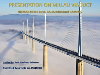
- 1. Guided By: Prof. Ravindra Srivastav Submitted By: Jayanta Sen (AB18005)
- 2. The Millau Viaduct, the tallest bridge in the world, located at near Millau city in France. It has 2.46km long with 7 piers in which pier 2 is the tallest with 343 meters high which is 20 meters taller than Eiffel Tower. The cost of construction was approximately € 394 million. It was built over three years, formally inaugurated on 14 December 2004, and opened to traffic two days later on 16 December.
- 3. To ease the flow and reduce journey times for long distance traffic. To reduce traffic congestion due to summer holiday. To improve the quality of access to Millau for its local businesses and residents. Traffic jams during summer time will reduce. House prices had been gone up & social development. Increase in economy from tourism. Toll station collection recover 478 million dollars investment of Construction Company
- 4. Work started 16th October, 2001 16th October, 2001 Completion of all 7 Piers with foundation December, 2003 November, 2003 Completion of Steel Road deck erection May, 2004 28th May, 2004 Opening of Viaduct for Public 10th January, 2005 16th December, 2004
- 5. Client Consultants Contractors Sub Contractors The French Government Architect: Foster and Partners Main Contractor: Compagnie Eiffage du Viaduc de Millau Concrete Contractor: Eiffage TP, Paech Concrete Supplier: Lafage Bitumen Supplier: Appia Shuttering Material Supplier: PERI Gmbh Electrical Contractor: Forclum Structural Steel Designer: Greisch Steelwork Contractor: Eiffel Hydraulic Support: Enerpac Prestressing Contractor: Freyssinet Project Manager: Setec, SNCF
- 6. Public – Private – Partnership (PPP). MOA Contract (As Developer) - Compagnie Eiffage du Viaduc de Millau. MOE Contract (As Prime Contractor). Creating firm RCC base foundation. Laser marking and plasma cutting used at workshop for fabrication. For erection of pylon they used ancient technique of Egypt. Hydraulic launching system used to erecting steel road deck. Used GPS and Satellites to reach specific point in the air.
- 7. Challenges Faced Action taken to overcome challenges Fracture and Cavities at Limestone valley bed Creating firm RCC base foundation for pier. Landslides due to heavy rainfall They built RCC retaining wall to stabilize the slope. Huge concrete usage Lafarge built dedicated concrete plant in site itself. Bridge piers vertical in plumb GPS Satellites signals used for proper positioning of structures. Every pier had different geometric shape Changed in shuttering mould in every 4m height rises. Transportation issue half fabricated parts of steel road deck They had planned a safe corridor for smooth and less eventful transportation. Coordinate with local police and authority. Erection of steel road deck Construction of temporary steel frame piers in between original piers to support movement of road deck. Using Hydraulic lunching system which pushes the steel road deck 600mm in single push. Hydraulic lunching system failure The Teflon sheet ware off for friction. The hydraulic system had in functioned by replacement of Teflon sheet. Wind pressure on road deck By wind tunnel testing it had assured. Financial The lack of public funds available to construct Millau Viaduct (approximately € 400 million). Undulation after full erection completed Placed pylon on proper position and stressed the cable weir.
- 8. Construction team face major problem regarding the position of piers. If pier plumb deviates 10cm from its position at bottom then it deviates 6 m away from its desire location at the top. Then team came up with the idea of using GPS equipment fixed on the piers then this GPS spends the signal to Satellites to record the position of piers till it reach the target in the sky. The pier had only 2cm deviation form its original position. It also used for final joining of the road deck and deviation lies in 1cm for through out 2.5km long bridge road deck.
- 9. This method was used to push the steel road deck over bridge piers. The trick was to use 4 of this launching system to jack up the deck and inch it forward each system used two wedge shape log under each side of the deck. The upper wedge was pulled by the hydraulic round, its slide up the slope of the bottom wedge at same time lifting up the deck by upper wedge at advancing it at 600 mm then lower wedge retract dropping the deck to its support by upper wedge and process repeats.