
Recommended
More Related Content
Similar to integrated circutits -324567654-12-345-.pptx
Similar to integrated circutits -324567654-12-345-.pptx (20)
Recently uploaded
Recently uploaded (20)
integrated circutits -324567654-12-345-.pptx
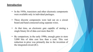
- 1. • In the 1950s, transistors and other electronic components were available only in individual packages. • These discrete components were laid out on a circuit board and hand connected using separate wires. • At that time, an electronic gate capable of storing a single binary bit of data cost more than $2. • By comparison, in the early 1990s, enough gates to store 5,000 bits of data cost less than a cent. This vast reduction in price was primarily due to the invention of the integrated circuit (IC). Introduction
- 2. Integrated Circuits “IC” • It’s a small silicon semiconductor, called a chip, containing the electronic components for the digital gates. The gates are interconnected inside the chip to form the required circuit.
- 3. ICs are classified according to their complexity • Small-scale Integration (SSI): contains several independent gates in a single package. The number of gates is usually fewer than 10. • Medium-scale Integration (MSI): have a complexity between 10 and 100 gates in a single package. They perform specific digital operations such as decoders, adders, and multiplexers. • Large-scale Integration (LSI): contains between 100 and 1000s gates in a single package. They include processors, memory chips, and programmable logic devices. • Very Large-scale Integration (VLSI): contains thousands of gates in a single package. Examples complex microcomputer chips. • Ultra large-scale integration (ULSI): 100,000 gates per chip. It describes very large memories, larger microprocessors.
- 4. Some Families of ICs
- 5. Transistor-Transistor Logic (TTL) • The most popular and widely used family of digital devices, which was invented in 1964. • Replace all the input diodes in a DTL gate with a transistor. • Result , became the standard logic circuit in most applications. • 5400 , 7400 series ICs.
- 6. Emitter-Coupled Logic (ECL) • Also known as Current Mode Logic (CML). • Invented at IBM in August 1956 • Very fast as compared to digital logic families. • Designed to operate at extremely high speeds. • Used in supercomputers.
- 7. CMOS Logic • Complementary Metal Oxide Semiconductor. • Invented by Frank Wanlass in 1963. • Limited in their speed of operation • It requires almost no current to operate. • Useful and effective in a wide range of battery- powered applications.
- 8. Characteristics of digital ICs used to compare their performances 1. Speed of operation. 2. Power dissipation. 3. Current and voltage parameters. 4. Noise immunity. 5. Operating temperature range. 6. Power supply requirements. 7. Flexibilities available.
- 9. Logic Representation There are three common ways in which to represent logic. 1. Truth Tables 2. Logic Circuit Diagram 3. Boolean Expression
- 10. Truth Tables • A truth table is a chart of 1s and 0s arranged to indicate the results (or outputs) of all possible inputs. • The list of all possible inputs are arranged in columns on the left and the resulting outputs are listed in columns on the right. • There are 2 to the power n possible states , for example with three inputs there are 2^3=8 possible inputs.
- 11. Logic Diagram A logic diagram uses the pictorial description of logic gates in combination to represent a logic expression. This example shows a logic diagram with three inputs (A, B, and C) and one output (Y). Boolean Expression Boolean Algebra can be used to write a logic expression in equation form.
- 12. Logic gates • A logic gate is a device that acts as a building block for digital circuits. • They perform basic logical functions that are fundamental to digital circuits. • Most electronic devices we use today will have some form of logic gates in them. • In a circuit, logic gates will make decisions based on a combination of digital signals coming from its inputs. • Most logic gates have two inputs and one output.
- 13. Logic Gates The Inverter • The inverter performs the operation called inversion or complementation. • It changes one logic level to the opposite level. In terms of bits, it changes a 1 to a 0 and a 0 to a 1.
- 14. The AND Gate • The AND gate is composed of two or more inputs and a single output. • An AND gate produces a HIGH output only when all of the inputs are HIGH. • When any of the inputs is LOW, the output is LOW.
- 15. The OR Gate • An OR gate has two or more inputs and one output. • An OR gate produces a HIGH on the output when any of the inputs is HIGH. • The output is LOW only when all of the inputs are LOW.
- 16. The NAND gate • It can be used as a universal gate. • The term NAND is a contraction of NOT-AND and implies an AND function with a complemented (inverted) output. • A NAND gate produces a LOW output only when all the inputs are HIGH. • When any of the inputs is LOW, the output will be HIGH
- 17. The NOR Gate • It can also be used as a universal gate. • The term NOR is a contraction of NOT- OR and implies an OR function with an inverted (complemented) output. • A NOR gate produces a LOW output when any of its inputs is HIGH. • Only when all of its inputs are LOW the output HIGH.
- 18. The Exclusive-OR Gate • For an exclusive-OR gate, output is HIGH when input A is LOW and input B is HIGH. • Or when input A is HIGH and input B is LOW. • The output is LOW when A and B are both HIGH or both LOW.
- 19. The Exclusive-NOR Gate • The bubble on the output of the XNOR symbol indicates that its output is opposite that of the XOR gate. • For an exclusive-NOR gate, output X is LOW when input A is LOW and input B is HIGH. Or when A is HIGH and B is LOW. • X is HIGH when A and B are both HIGH or both LOW.
- 20. THANK YOU