FEA Based Level 3 Assessment of Deformed Tanks
•
0 likes•40 views

The presentation describes how to integrate Laser Scan Data into FEA Model and Perform Level 3 Fitness-for-Service Assessment of Critical Assets in Refinery & Process Industries. It also, talks about an engineer friendly plugin that helps in the data import with insights from the asset owners and FEA consultants.

Recommended
Recommended
More Related Content
What's hot
What's hot (20)
Similar to FEA Based Level 3 Assessment of Deformed Tanks
Similar to FEA Based Level 3 Assessment of Deformed Tanks (20)
More from Arindam Chakraborty, Ph.D., P.E. (CA, TX)
More from Arindam Chakraborty, Ph.D., P.E. (CA, TX) (20)
Recently uploaded
Recently uploaded (20)
FEA Based Level 3 Assessment of Deformed Tanks
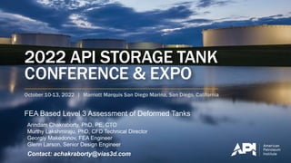
- 1. FEA Based Level 3 Assessment of Deformed Tanks Arindam Chakraborty, PhD, PE, CTO Murthy Lakshmiraju, PhD, CFD Technical Director Georgiy Makedonov, FEA Engineer Glenn Larson, Senior Design Engineer Contact: achakraborty@vias3d.com
- 2. Who We Are • Multiple Industry Experience – Processing & Refinery, Oil & Gas, Marine and Offshore, Manufacturing, Machinery & Equipment and other industries. • Global Presence with HQ in Houston, USA • Global team of +170 professional with Engineering Services team consisting of +30 professional with majority having PhDs and MSc/MTechs with expertise in Design & Manufacturing, Structural & Solid Mechanics, Fluid Mechanics, Electromagnetics, Optimization & Reliability, Data Analytics, System Architecture, Bioscience and Materials, Automation, .. • Dassault Systèmes Platinum Partner – Global Presence – Part of DS Advisory Group • Provide Software Sales and Support, Training, Engineering services & technical resource augmentation, PLM implementation, Automation and Customization Engineering Services Training Automation & Customization Software
- 3. Industries We Serve - ALL Marine & Offshore Oil & Gas Industrial Equipment Aerospace and Defense High-Tech Geotech & Geomech Consumar Product Goods Life Sciences Energy, Process, Utilities Nuclear: New Construction, In-Service, Decommissioning Architecture, Engineering and Construction Transportation & Mobility
- 4. • “Oil and gas industry is playing a significant role in the growth of Storage Tank Market” • “The Global Storage Tank Market appraised at USD 12.56 billion in 2019 is expected to touch USD 16.87 billion by 2027”, – Global Storage Market Size, Report, 2020 Since 1965: • ~74% of storage tank accidents occurred in petroleum refineries or oil terminals. • ~30% of all storage tank accidents worldwide occurred due to poor operation and maintenance Guru Gobind Singh Refinery, India (2012) “Disaster at Pittsburgh” Oil Tank Collapse (1988) Design Codes API 650 (2019) – Welded Tanks for Oil Storage API 579 (2016) – Fitness for Service ASME BPVC VIII – Division 2 - Alternative Rules ASME BPVC II – Materials - Part D – Properties
- 5. Objective Integrate Laser Scan Data into FEA Model to Perform Level 3 Fitness-for- Service Assessment of Critical Assets in Refinery & Process Industries 5
- 6. What is FFS? • Methodology and procedures determines whether an existing engineering structure is able to perform its intended function under operating loads. • There are calculation methods and procedures to assess whether a structure is operable as it is, needs repair or should be replaced altogether. • FFS assessments usually require a standard list of information such as original design conditions, materials of construction, and operation and maintenance history.
- 7. Benefits of FFS Assessment OPERATIONAL AND MAINTENANCE REDUCED COSTS MAINTAIN MECHANICAL INTEGRITY OF ASSETS EXTENSION OF ASSETS SERVICE LIFE COMPLIANCE OF REGULATION FOR A SAFE OPERATION
- 8. Workflow Overview Importing Scan Data and Navigate Cleaning Data Shape Regeneration Geometry import to Abaqus Assigning Material Properties and Sections Meshing Application of Loads and BCs Analysis Post-processing / Integrity Assessment
- 9. Workflow (Steps 1 and 2) Step 1 – Import and Navigate • Import 10mm x 10mm filtered laser scan data. • Original data is in ASCII format. • Scale and trim the data using Digital Shape Preparation app. Step 2 – Cleaning Data • The surface generated was based on the down-sampling of the point cloud data to achieve a smother surface with least deviation. • The laser scan data is so accurate that you can see the heat radiation from welding. • Trim and clean the data to remove erroneous points. Step 1: Import and Navigate Step 2: Cleaning Data
- 10. Tank Surface Generation Analysis • Catia Digital Shape Editor uses an algorithm to homogenize the data to find the tangent results needed to create the surface • This method removes points that cannot possibly be part of a manufactured surface. • The result is checked against the original unfiltered point cloud for deviation. • This ensures that you can see what we are removing, making a clean surface that represents the actual manufactured surface. The deviation analysis in shows that the majority of points on the surface deviate from the point cloud data between 0 to 25 mm.
- 11. Workflow (Steps 3 and 4) Step 3 – Shape Regeneration • Easily transform a 3D scan into a clean surface. • The Reverse Engineering role contains also all the features needed to work with cloud points and scan, such as smoothing, surface network, etc. Step 4 – Geometry Import to Abaqus • Tank surface was imported in Abaqus/CAE as a .STP file to • Nozzles, appurtenances and rafters were not included in the FEA. • Bottom plate added to the tank bottom as a shell extension Step 3: Shape Regeneration Step 4: Geometry Import to Abaqus
- 12. Workflow (Steps 5 and 6) Step 5 – Assigning Material Properties and Section • Assign the section to the part with appropriate thickness (cloud thickness data can be used) • Assign the material properties (SA-387) • Elastic modulus =200 GPa • Yield Strength = 245 MPa Step 6 – Meshing • Assign the mesh to the part. • Refine the mesh in the areas of high concern (create partitions if necessary). • Number of surface elements S4R, shell reduced integration, quadrilateral) ~ 350,000 Step 5: Assigning Material Properties and Section Step 6: Meshing
- 13. Evaluation Criteria • Level 3 FFS assessment requires plastic collapse, local failure and nonlinear buckling checks for mechanical integrity of a structure • Plastic collapse – structure’s global capacity to sustain the applied loads • Criteria – complete convergence of analysis (structure can sustain the applied loads) • Local failure – a measure of a structure’s plastic strain against a plastic strain limit. • Criteria – equivalent plastic strain must be lower the plastic strain limit. • Nonlinear buckling – determines the local cross-sectional buckling capacity of the structure under the given loads • Criteria – a load proportionality factor (LPF) greater than 1.0 indicates that the structure will not buckle until load greater the applied loads is achieved. Analysis Case Analysis LF (D,P,Ps) LF (W) LF (Ss) LF (E) Case 1 – Plastic Collapse Linear Elastic 1.0 1.0 1.0 N/A Case 2a – Plastic Collapse Elastic-Plastic 2.2 N/A N/A N/A Case 2b – Plastic Collapse Elastic-Plastic 2.0 0.8 2.5 N/A Case 2c – Plastic Collapse Elastic-Plastic 2.0 1.5 0.8 N/A Case 2d – Plastic Collapse Elastic-Plastic 2.0 1.5 0.8 N/A Case 2e – Plastic Collapse Elastic-Plastic 2.0 N/A 0.8 1.5 Case 3 – Local Failure Elastic-Plastic 1.5 N/A N/A N/A Case 4 – Nonlinear Buckling Elastic-Plastic 2.0 1.5 0.8 N/A
- 14. Workflow (Steps 7 and 8) Step 7 – Application of Boundary Conditions • Apply the appropriate boundary conditions • Bottom surface is fixed (no translation, no rotation) Step 8 – Application of Loads • Force is applied at a reference point coupled to inner surface of tank • Apply the appropriate loading conditions (in addition to gravity): • Wind design speed • Wind pressure load • Internal Hydrostatic Pressure • Design Temperature • Vacuum Pressure • Snow Load • Seismic load Steps 7 and 8: Application of Loads and BC Load Cases
- 15. Workflow (Steps 9) Step 9 – Results Analysis • The results show that the tank passes plastic collapse, local failure and buckling checks assessment as stipulated in API 579. • Some plastically deformed areas are observed in tank shell (shown by red colors). • The governing load for plastic collapse turned out to be the hydrostatic load case. Plastic Collapse (Elastic-Plastic) Bottom Ring Local Failure (Elastic-Plastic) NL Buckling Analysis Plastic Collapse (Linear Elastic)
- 16. Conclusions • The tank shell passes the FFS criteria of API 579 code (plastic collapse, local failure, buckling). • Tank is fit for service at design conditions. • No repairs or reinforcements are required to operate the tank based on assessed conditions. • It is recommended that non-destructive testing (NDT) of high distortion points throughout the tank be performed. Analysis Case Analysis Result LC 2a (Dead weight, pressure) Pass LC 2b (Dead weight, pressure, snow, wind) Pass LC 2c (Dead weight, pressure, snow, wind) Pass LC 2d (Dead weight, external pressure, snow, wind) Pass LC 2e (Dead weight, external pressure, snow, seismic) Pass Local Failure Pass Nonlinear Buckling Pass
- 17. Efficient Simulation using AI-ML RAW DATA (INPUT) DATA STRUCTURING TRAINING ML, ANN PREDICTIONS Output of Interest (stress, deformation, pressure,..) ML, ANN, autoencoder CNN, RNN
- 18. Liquid Sloshing Convective Model Analysis of Fluid Sloshing (From Literature) • The study will be extended to simulate the effects of combined tank deformations and fluid sloshing due to seismic ground excitations to estimate the deformations of the critical structural components due to fluid loading • Fluid-structure interaction between the fluid and structural components (tank wall, bottom plate, and roof structure) shall be modeled using a two-way coupled approach Image Source: Çelik, Ali & KÖSE, Mehmet & Akgül, Tahir & APAY, Ahmet. (2018). DIRECTIONAL-DEFORMATION ANALYSIS OF CYLINDRICAL STEEL WATER TANKS SUBJECTED TO EL-CENTRO EARTHQUAKE LOADING. 1033-1046.
- 19. Plugin Development • Workflow automation provides a parametric flexibility for repetitive tasks and makes the process more efficient. • Plug-in development of customized interface based on user input data • Inputs that can be easily modified: • Scan data file selection • Origin shift • Node move process • Node smooth process • etc. Contact us for more information on how we can help.
- 20. Summary Accurately capturing surface distortion through laser scan data is of paramount importance. Multiple load combinations can be assessed efficiently to determine worst combination of directional loads and surface distortions. Using 3DEXPERIENCE platform, geometrical surface derived from point cloud data can be seamlessly integrated into the FEA workflow to perform high fidelity FFS assessment using Abaqus. The workflow presented here can be used for reliability studies by introducing variances in measured data and or by introducing surface profiles for areas lacking measurements. 20
Editor's Notes
- Çelik, Ali & KÖSE, Mehmet & Akgül, Tahir & APAY, Ahmet. (2018). DIRECTIONAL-DEFORMATION ANALYSIS OF CYLINDRICAL STEEL WATER TANKS SUBJECTED TO EL-CENTRO EARTHQUAKE LOADING. 1033-1046.