
Recommended
More Related Content
Similar to electrical drawings.pdf
Similar to electrical drawings.pdf (20)
Recently uploaded
Recently uploaded (20)
electrical drawings.pdf
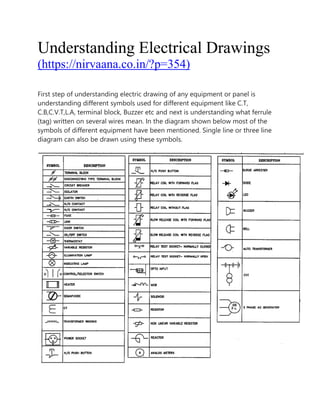
- 1. Understanding Electrical Drawings (https://nirvaana.co.in/?p=354) First step of understanding electric drawing of any equipment or panel is understanding different symbols used for different equipment like C.T, C.B,C.V.T,L.A, terminal block, Buzzer etc and next is understanding what ferrule (tag) written on several wires mean. In the diagram shown below most of the symbols of different equipment have been mentioned. Single line or three line diagram can also be drawn using these symbols.
- 2. Understanding different ferrules : Several wires run from control room to different equipment in the switchyard of a substation to operate and monitor these equipment from remote i.e from the control room. These wires are laid usually through underground cable trenches .These wires are also tagged for identification as well as rectification of fault if any , faulty cable or wire can be traced easily with name tags on it. Tags are also called ferrule and they appear on wires as K1,C11,D33,U11,E31 etc .The first Alphabet K,C,D,U,E etc of these tags have specific meaning and one can know for what specific purpose they are being used. Following is Ferrule numbering standards: Ferrule “A” used for: CT circuit -Main Protection Ferrule “B” used for : CT circuit -Busbar Protection Ferrule “C” used for : CT circuit -Backup Protection Ferrule “D” used for : CT circuit-Metering circuit Ferrule “E” used for : PT circuit-Protection/Metering circuit Ferrule “G” used for: PT circuit-Synchronizing Ferrule “H” used for: Auxiliary AC circuit Ferrule “J” used for: Auxiliary DC circuit Ferrule “K” used for: Control circuit (DC) Ferrule “L” used for: Alarm and Indication circuit Ferrule “P” used for: DC circuit-Busbar Protection
- 3. Ferrule “S” used for: Event logger/SCADA/BCU circuits Ferrule “U” used for: Spare Cont Now that we have understanding of different symbols and ferrules ,let us try to understand the diagram below which is of circuit breaker closing circuit from remote i.e from control panel : 52 CB in the drawing below is a Circuit Breaker which is usua switchyard and 195,295, 86 relays etc are housed in a control and relay panel which is located in Control room. From the diagram it is clear that +Ve DC supply for remote closing is taken from Circuit breaker itself ,it first enters the panel in the terminal block(T.B) shown as HV52TB4.03 , name of T.B is HV52TB4 and the wire connects in no.03 position of this T.B. A terminal block looks like this and it is numbered serially from 1 to its max capacity: Ferrule “S” used for: Event logger/SCADA/BCU circuits Ferrule “U” used for: Spare Contacts Now that we have understanding of different symbols and ferrules ,let us try to understand the diagram below which is of circuit breaker closing circuit from remote i.e from control panel : 52 CB in the drawing below is a Circuit Breaker which is usually located in the switchyard and 195,295, 86 relays etc are housed in a control and relay panel which is located in Control room. From the diagram it is clear that +Ve DC supply for remote closing is taken from first enters the panel in the terminal block(T.B) shown as HV52TB4.03 , name of T.B is HV52TB4 and the wire connects in no.03 position of this T.B. A terminal block looks like this and it is numbered serially from 1 to its Now that we have understanding of different symbols and ferrules ,let us try to understand the diagram below which is of circuit breaker closing circuit from lly located in the switchyard and 195,295, 86 relays etc are housed in a control and relay panel From the diagram it is clear that +Ve DC supply for remote closing is taken from first enters the panel in the terminal block(T.B) shown as HV52TB4.03 , name of T.B is HV52TB4 and the wire connects in no.03 position of this T.B. A terminal block looks like this and it is numbered serially from 1 to its
- 4. From the mentioned T.B ,ferrule K310 is the wire which carries +Ve DC supply ahead and it connects with the DC fuse shown as FS27-6A , after this fuse it enters into protective relays -195,295 & 86 relay and then further to Trip and Close (TNC) switch of the Panel. Only when the relay contacts of 86 HV ,86 LV &195 is closed , +Ve DC supply will reach TNC switch terminal for closing the breaker. When any relay is in operated condition, the relay contacts will open and it will not allow DC voltage to pass through it and close the C.B. Therefore for closing the C.B all relays should be reset. As soon as the +Ve DC voltage is available on ferrule K314 , it will be available on one end of TNC switch, and when this switch is moved to close position ,+Ve DC voltage reaches the closing coil in the Circuit breaker which turns on the breaker. It is to be noted that trip and closing coil of breaker is given -Ve supply at all times and +Ve supply is extended through relays and TNC switch. For understanding more about testing & commissioning ,please visit: https://nirvaana.co.in/?p=354