
Recommended
More Related Content
Viewers also liked
Viewers also liked (20)
Similar to Virtual projector
Similar to Virtual projector (20)
Recently uploaded
Recently uploaded (20)
Virtual projector
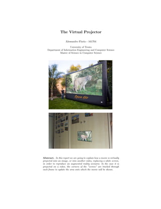
- 1. The Virtual Projector Alessandro Florio - 161704 University of Trento Department of Information Engineering and Computer Science Master of Science in Computer Science Abstract. In this report we are going to explain how a movie is virtually projected into an image, or into another video, replacing a white screen, in order to reproduce an augmented reality scenario. In the case it is projected on a video, the corners of the ”screen” are tracked through each frame to update the area onto which the movie will be shown.
- 2. Table of Contents 1 Introduction. . . . . . . . . . . . . . . . . . . . . . . . . . . . . . . . . . . . . . . . . . . . . . . . . . . 2 2 Screen corners initialization . . . . . . . . . . . . . . . . . . . . . . . . . . . . . . . . . . . . . 2 2.1 Image mode . . . . . . . . . . . . . . . . . . . . . . . . . . . . . . . . . . . . . . . . . . . . . . 3 2.2 Video mode . . . . . . . . . . . . . . . . . . . . . . . . . . . . . . . . . . . . . . . . . . . . . . 3 3 Projecting the movie . . . . . . . . . . . . . . . . . . . . . . . . . . . . . . . . . . . . . . . . . . . 4 4 Conclusion . . . . . . . . . . . . . . . . . . . . . . . . . . . . . . . . . . . . . . . . . . . . . . . . . . . . 5 1 Introduction The program can project a movie both on a still image which contains a screen, and on a video in which the screen moves due to rotations and translations of the camera. The code has been implemented in a way that, after compiling the source, if the generated executable is called without arguments1 it runs by default the video mode. If instead it is executed with an argument2 , whatever this may be, it runs the image mode. This has to be kept in mind when running the executable file with the ”-r” option which saves the execution to a video file called output.avi: in fact, adding this option toggles the execution mode for the rule described above (see also the relative footnotes)! In the following sections we are going to describe in detail how the algorithm has been implemented, always explaining the differences and similarities between the image and video mode. 2 Screen corners initialization The procedure of initializing the screen corners follows two different approaches in the image and video modes: for the first one it is manual, so that it can be easier to change the image with the screen on which the movie is projected, while for the second one it is automatic, but in order to be so it needs to do some image cleaning which was studied for the provided video and which may not adapt to all situations. 1 or with an even number of arguments 2 or with an odd number of arguments
- 3. 2.1 Image mode As mentioned above, in the image mode users can select the four points of the image which represent the screens corners. This is done by clicking with the left mouse button at the right position. In case of mistake, pressing ’c’ will clear all the inserted points. When the four points have been correctly marked, by pressing ’s’ the projection starts. 2.2 Video mode Differently from the image mode, in the video mode the four corners are identified automatically as the four best features to track3 in the first video frame. To do so, the screen was constructed as a white area with a black solid border in order to increase the contrast on the extremities. The frame is then converted to the grayscale color space, and subsequently binary thresholded to simplify the identification between screen, border and the rest of the environment. Since the border is quite thick, each corner would be identified twice: the binary image is therefore substituted by its skeleton. Then, the identification of the corners is immediate; when this last operation is completed, the projection can start. 3 see [1]
- 4. 3 Projecting the movie Projecting the movie as in an augmented reality scenario is just a matter of warping every frame of the movie using a perspective transformation in order to fit in the actual screen position. While the perspective transformation in the image mode has to be computed only at the beginning - since the screen does not move, and so its corners do not change - in the video mode, where the screen position changes from frame to frame, the corners have to be tracked and the projection has to be recomputed every time. Tracking is performed through the OpenCV function calcOpticalFlowPyrLK which calculates an optical flow for a sparse feature set using the iterative Lucas-Kanade method with pyramids4 . The warped image is computed using the OpenCV function getPerspectiveTransform which, given in input the four absolute corners of the movie and the four corresponding corners of the screen5 calculates the 3 × 3 matrix M of a perspective transform such that: tixi tiyi ti = M · xi yi 1 where (xi, yi) is the ith corner of the movie (xi, yi) is the ith corner of the screen for i = 0...3 We recall that the matrix has to be computed only once in the image mode, but has to be recalculated at every frame, after identifying the new positions of the screen’s corners through the optical flow computation, in the video mode. The projection matrix M is used for every frame of the movie in the OpenCV function warpPerspective which creates a new image from the source movie frame where dst(x, y) = src M11x + M12y + M13 M31x + M32y + M33 , M21x + M22y + M23 M31x + M32y + M33 . The warped movie frame is then copied on the screen, removing all the black pixels left from the transformation which lie outside its border. 4 see [2] 5 corners both of the movie and of the screen were ordered clockwise starting from the top-left one
- 5. 4 Conclusion We have implemented a virtual projector which suits an augmented reality sce- nario and which is very stable and generates a fluid and realistic video. The program can also save the execution to a video file6 , so the output can be used for other applications. To sum up, we present here a pseudo-code of the algorithm, which recaps in short the main parts of the implementation: // media definition Mat frame if IMAGE MODE then frame ← screenImage else if VIDEO MODE then frame ← video.at(0) end // corners’ initialization Point[] corners if IMAGE MODE then corners ← frame.getFourPointsFromUser() else if VIDEO MODE then frame.convert(gray) frame.threshold(binary) frame.opening() frame.thin() corners ← goodFeaturesToTrack(frame, 4) end int w ← movie.cols - 1 int h ← movie.rows - 1 Point[] movieCorners ← {(0,0), (w,0), (w,h), (0,h)} Mat projectionMatrix if IMAGE MODE then // order the cornes as movieCorners, so they can be correcly mapped corners.orderClockwiseFromTopLeft() projectionMatrix ← getPerspectiveTransform(corners, movieCorners) end // continues on next page... 6 as described in the second paragraph of the Introduction
- 6. // play the movie forall movieFrame do if VIDEO MODE then /* compute the corner’s actual position based on the optical flow * between the previous and the current frame, and the previous * corners’ positions */ corners ← calcOpticalFlowPyrLK(prevFrame, frame, corners) // order the cornes as movieCorners, so they can be correcly mapped corners.orderClockwiseFromTopLeft() // re-compute the projection matrix for this frame projectionMatrix ← getPerspectiveTransform(corners, movieCorners) end Mat projection ← warpPerspective(movieFrame, projectionMatrix) projection.copyNonZeroPixelsTo(frame) show(frame) end References 1. Jianbo Shi and Carlo Tomasi, ”Good features to track” 2. Jean-Yves Bouguet, ”Pyramidal Implementation of the Lucas Kanade Feature Tracker Description of the algorithm” 3. http : //docs.opencv.org/modules/video/doc/motion analysis and object tracking.html 4. http : //docs.opencv.org/modules/imgproc/doc/geometric transformations.html